I. INTRODUCTION
The functionality, lifetime, and future commercial success of novel nanoelectronic and nanoelectromechanical devices will ultimately depend on a fundamental understanding of the physical properties and reliability of submicron and nanometer-sized structures comprising them. One major concern is that the deformation behaviors and key mechanical properties of materials change significantly with decreasing device dimensions. A great deal of recent work, as reviewed by Uchic et al.,Reference Uchic, Shade and Dimiduk1 Kraft et al.,Reference Kraft, Gruber, Mönig and Weygand2 and Greer and De Hosson,Reference Greer and De Hosson3 has shown that the mechanical strength of single-crystalline face-centered cubic (FCC)Reference Uchic, Dimiduk, Florando and Nix4–Reference Ng and Ngan12 and body-centered cubic (BCC)Reference Kim and Greer13–Reference Han, Bozorg-Grayeli, Groves and Nix17 metals is strongly dependent on size, with reduced dimensions yielding stronger specimens. The same smaller-is-stronger effect has been observed in other crystalline systems, such as tetragonal,Reference Burek, Budiman, Jahed, Tamura, Kunz, Jin, Han, Lee, Zamecnik and Tsui18 rhombohedral,Reference Burek, Jin, Leung, Jahed, Wu, Budiman, Tamura, Kunz and Tsui19 and hexagonal close packed (HCP).Reference Lilleodden20–Reference Jin, Burek, Evans, Jahed and Tsui26 Size-dependent mechanical behaviors in nanoscale metals are generally attributed to the competition between the rate of dislocations generated by applied stress and the rate of dislocation annihilation at free surfaces.Reference Greer and Nix27–Reference Shan, Mishra, Syed Asif, Warren and Minor29 With decreasing sample size, the rate of dislocation annihilation during applied stress exceeds that of dislocation generation, thus yielding a crystal, which has a much lower dislocation density or is even completely absent of dislocations.Reference Shan, Mishra, Syed Asif, Warren and Minor29 In this “dislocation starved” state, further loading will be accommodated by elastic deformation until the applied stress is sufficient to nucleate new dislocations.Reference Greer and Nix27, Reference Shan, Mishra, Syed Asif, Warren and Minor29 Therefore, decreasing sample dimensions will yield stronger specimens due to the reduced dislocation density. Among the crystalline structures studied at the nanoscale, HCP metals are particularly interesting since they deform not only by dislocation glide along active slip systems but also deform by twin boundary formation.
Recently, LilleoddenReference Lilleodden20 reported size effects in the mechanical strength of micron scale single-crystalline HCP magnesium pillars through uniaxial microcompression techniques. These columnar structures, with diameters in the range of 2–10 μm and (0001) orientation, were manufactured using focused ion beam (FIB) milling. Results of this study show the magnesium micropillar flow stresses increase with the reduction of the sample dimensions, similar to small scale FCC, BCC, tetragonal, and rhombohedral specimens. Analysis of compressed magnesium micropillars by cross-sectional electron back-scattered diffraction indicated that twinning is not the predominant deformation mechanism. In a similar study, Byer et al.Reference Byer, Li, Cao and Ramesh21 compressed single-crystalline [0001] magnesium micropillars, again fabricated by FIB milling, and did not observe twinning in the deformed samples. However, their results do not indicate strength size dependence, which contradicts with the results by Lilleodden.Reference Lilleodden20 Ye et al.Reference Ye, Mishra, Sachdev and Minor25 recently reported on the uniaxial compression of single-crystalline magnesium pillars performed in situ within a transmission electron microscope (TEM). In their work, it was demonstrated that there are strong size effects associated with basal plane sliding and extension twinning in magnesium pillars. Twinning and reorientation of the crystal was also observed by Kim et al.Reference Kim, Yi, Huang, Lilleodden, Lou, Lilleodden, Boyce, Lu, Derlet, Weygand, Li, Uchic and Le Bourhis22 during uniaxial compression of < > single-crystalline magnesium small-scale pillars.
Single-crystalline HCP titanium—5% aluminum alloy was also examined at the submicron scale by Yu et al.Reference Yu, Shan, Li, Huang, Xiao, Sun and Ma23 Uniaxial compression of FIB fabricated titanium alloy micropillars revealed that the flow stresses increase with a power law function for dimension greater than 1 μm, and that deformation of these specimens was dominated by twinning. Contrastingly, titanium alloy pillars with size less than 1 μm did not exhibit a size effect and no twin boundary formation was observed. Instead, these smaller specimens all deformed at a constant flow stress near the theoretical strength for titanium, and dislocation plasticity was revealed to be the dominant deformation mechanism. It was also reported that, in some cases, deformed submicron titanium alloy pillars exhibited limited barreling effects similar to those generated by mechanical constraints at the nanoindenter–pillar interface. More recently, Sun et al.Reference Sun, Guo, Yao, Xiao, Greer and Sun24 reported on the uniaxial compression of FIB fabricated single-crystalline titanium micropillars with [11 0] orientation, such as to activate prismatic slip. Results of compression tests on these titanium pillars, ranging in effective diameter from 0.3 μm to several microns, demonstrated a pronounced size effect following a power law relationship. Interestingly, the smallest titanium specimens tested by Sun et al.Reference Sun, Guo, Yao, Xiao, Greer and Sun24 reached approximately 16% of the theoretical strength of titanium, a result much different than those titanium alloy micropillars tested by Yu et al.Reference Yu, Shan, Li, Huang, Xiao, Sun and Ma23 which were also fabricated by FIB milling.
The studies of magnesium and titanium micropillars have provided valuable insights into the deformation mechanisms, which dominate small-scale HCP crystals. However, certain common aspects of these works, such as micrometer specimen size, tapered pillar geometry, and uncertainties due to FIB fabrication,Reference Bei, Shim, Miller, Pharr and George30, Reference Zimmermann, Van Petegem, Bei, Grolimund, George and Van Swygenhoven31 warrant further investigation of HCP mechanical properties at the nanoscale. The objective of the current study is to further elucidate the deformation mechanisms governing small-scale HCP materials through uniaxial compression of zinc pillars with diameters ranging from approximately 100 nm to 1 μm. To the best of our knowledge, a detailed effort to investigate the deformation characteristics of nanometer scale zinc has yet to be performed. The lattice parameter for zinc is a = 2.6650 Å, with c/a ratio of 1.8563.Reference Cullity and Stock32 Zinc pillars tested in this study were prepared via electron beam lithography and electroplating techniques,Reference Burek and Greer33 which is a FIB-less fabrication method. Therefore, any uncertainties in the observed mechanical response originating from Ga+ ion implantation or ion induced microstructural damageReference Bei, Shim, Miller, Pharr and George30, Reference Zimmermann, Van Petegem, Bei, Grolimund, George and Van Swygenhoven31 are absent from this study. The FIB-less fabrication method also yields smaller specimens down to ∼130 nm in diameter and eliminates any pillar tapering. Additionally, zinc has a low melting temperature (T m ∼ 419 °C) compared to the other HCP materials studied at small length scale, such as titanium (T m ∼ 1668 °C) and magnesium (T m ∼ 650 °C). The homologous temperature for zinc at room temperature is approximately 0.43. Therefore, in ambient conditions, thermally activated deformation mechanisms are expected to be more significant in zinc compared to both titanium and magnesium.
Mechanical properties of bulk zinc have been well characterized. It has a shear modulus of 43 GPa, with a theoretical strength in the range of approximately 1.4–4.3 GPa. Like other HCP materials, deformation may be dominated by motion of dislocations, or by twin boundary formation. For HCP deformation by dislocation plasticity, there are three possible slip systems: basal, prismatic, and pyramidal. When compressed in a direction of 45° from the [0001] crystal axis, dislocation motions in the [ 2
 0] (0001) basal slip system have been observed by Adams et al.Reference Adams, Vreeland and Wood34 In a related work, Adams et al.Reference Adams, Blish and Vreeland35 uniaxially compressed a bulk zinc single crystal with the loading axis in [0001] direction and observed dislocation motions in the <1
 1
 > {1
 12} second order pyramidal slip systems. Twin planes of {10
 2} were observed by RosenbaumReference Rosenbaum36 during ball indentations of zinc single crystals. The creep properties of bulk polycrystalline and single-crystalline zinc were also characterized by Godavarti and MurtyReference Godavarti and Murty37 and Adams et al.Reference Adams, Blish and Vreeland35 In the work by Godavarti and Murty,Reference Godavarti and Murty37 the time dependent deformation behaviors of polycrystalline zinc at 423 K were examined using impression tests. The authors showed that the steady state impression velocity has a power law relationship with the impression stress. The stress exponents extracted from their results are in the range of 3.4–4.4. Adams et al.Reference Adams, Blish and Vreeland35 characterized the edge dislocation mobility in zinc single crystals by performing uniaxial compression tests along the [0001] direction. Their results demonstrated that the edge dislocation velocity has a power law relationship with resolved shear stress and a stress exponent value of 8.7.
In the present study, the deformation behavior of submicron scale zinc pillars was characterized by displacement controlled uniaxial compression tests, while the postdeformation microstructure evolution was studied using electron microscopy and electron diffraction techniques. The specimens were compressed with three different engineering strain rates of ∼10−2, 10−3, and 10−4 s−1. Electron microscopy results revealed that the zinc pillar deformation modes are not dominated by twinning. In addition, the mechanical strengths of these submicron scale structures do not exhibit strain rate sensitivity and are not dependent on size.
II. EXPERIMENTAL METHODS
Zinc submicron scale pillars were prepared using an electron beam lithography and metal electroplating method developed by Burek and Greer.Reference Burek and Greer33 This fabrication method has proved versatile in producing small-scale metallic structures for uniaxial compression tests.Reference Jennings, Burek and Greer10, Reference Burek, Budiman, Jahed, Tamura, Kunz, Jin, Han, Lee, Zamecnik and Tsui18, Reference Burek, Jin, Leung, Jahed, Wu, Budiman, Tamura, Kunz and Tsui19, Reference Jin, Burek, Evans, Jahed and Tsui26, Reference Greer, Kim and Burek38–Reference Jahed, Jin, Burek and Tsui41 The advantage of this technique over the conventional FIB milling process is the elimination of tapered geometries and the significant impact of high energy Ga+ exposure on the pillar microstructure.Reference Bei, Shim, Miller, Pharr and George30, Reference Zimmermann, Van Petegem, Bei, Grolimund, George and Van Swygenhoven31 Briefly, silicon (111) substrates coated with a 20-nm titanium adhesion layer and a 100-nm gold seed layer were first spin coated with polymethylmethacrylate (PMMA) electron beam lithography resist. An array of pores with various submicron scale diameters was then patterned using electron beam lithography. Room temperature electroplating from a solution containing 0.14 M zinc (II) sulfate heptahydrate and 0.16 M boric acid was used to deposit zinc into the patterned PMMA template. The titanium/gold seed layer acted as the cathode and a high purity zinc rod was used as a soluble anode. For the electroplating, a constant current density value of 5.0 mA/cm2 was maintained. After electroplating, the PMMA resist was removed with acetone. Four different zinc cylindrical column structures with average diameters of 130, 230, 550, and 1060 nm were successfully manufactured.
A nanoindenter (Nanomechanics Inc, Knoxville, TN) equipped with a diamond flat tip and operated in displacement-controlled mode was used for the uniaxial compression tests. Three different deformation rates were used: 10−2, 10−3, and 10−4 s−1. Only those specimens with an aspect ratio (height/diameter) in the range of ∼2–4 were selected for mechanical testing. To minimize any contributions of machine drift to the raw indentation displacement, the targeted nanoindenter drift rate was prescribed at 0.05 nm/s prior to all of the compression tests; with the exception of experiments performed at the strain rate of 10−4 s−1. The prescribed drift rate for the slowest deformation rate experiments was 0.01 nm/s, which is near the displacement resolution of the nanoindenter. Since the slowest strain rate (10−4 s−1) used in this work has nominal displacement velocity of ∼0.1–0.3 nm/s, it is possible that there is greater than 10% uncertainty in the measured displacement values during these experiments. Engineering flow stress and strain were calculated from the load—displacement data collected during compression experiments. The engineering stress is the ratio between the mechanical load applied and the initial cross sectional area of the pillars. Deformations were characterized as engineering strains, which were defined as the ratio between the length change of the pillar and its original height.
The microstructure of several as-fabricated and compressed 1060 and 550 nm diameter zinc pillars were characterized by bright-field TEM and selected-area electron diffraction (SAED) analysis. TEM samples of the selected zinc pillars were prepared by the standard FIB lift-out method.Reference Burek and Greer33
III. RESULTS AND DISCUSSIONS
A. Geometry and microstructure of as-fabricated zinc submicron structures
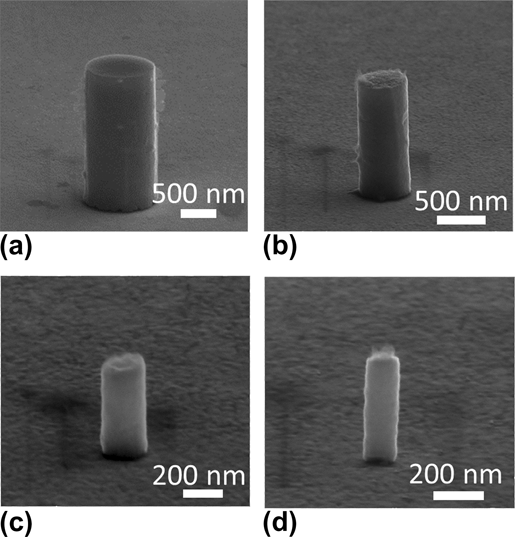
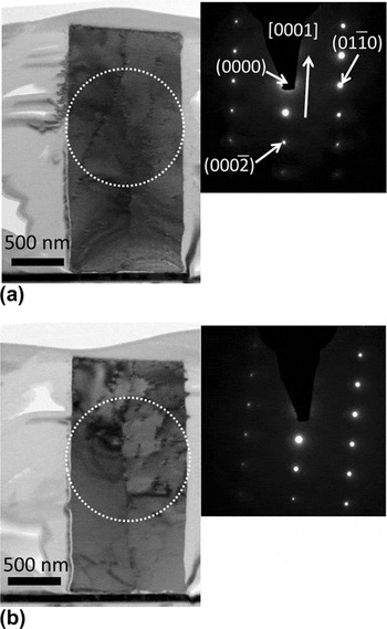
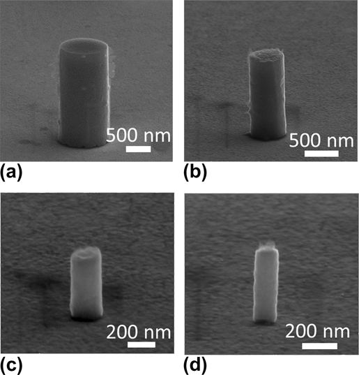
Scanning electron microscopy (SEM) images of as-fabricated zinc pillars with average diameters of 1060, 550, 230, and 130 nm are shown in Figs. 1(a)–1(d), respectively. A nearly perfect cylindrical geometry and smooth sidewalls are observed for all pillar sizes. There are no apparent grain boundaries or any other surface features, which would suggest a granular material. This nearly ideal geometry is quite unique, especially relative to FIB fabricated columnar structures of other HCP materials previously studied.Reference Lilleodden20–Reference Ye, Mishra, Sachdev and Minor25Figure 2 shows bright-field TEM images of two as-fabricated 1060-nm diameter zinc pillars and the corresponding SAED patterns collected from the circled areas. The sharp gold–zinc interface in TEM images confirms there is no interaction between the gold layer and zinc pillar. SAED patterns indicate that these particular specimens are indeed single crystalline, which is a strong indication that the ensemble of zinc samples fabricated in this work are most likely single crystalline, or, at most, consist of very large grains. Another important observation from the TEM analysis is that neither of the as-fabricated zinc pillars is pristine and both contain initial dislocations in the bulk of the structure. Some of these initial dislocation segments even extend nearly the entire height of the pillar. In some parts of these structures, the dislocation density appears to be quite high, for example, the top right of the pillar in Fig. 2(b). It is important to note that the actual number of dislocations contained within these zinc structure are significantly more than those shown in Fig. 2, because dislocations are invisible if g b = 0 is satisfied under two-beam conditions, where g is the diffracting vector and b is the Burgers vector. More dislocations were visible by tilting the samples to other zone axes (micrographs are not shown here). Unlike other HCP micron and submicron scale specimens produced by FIB milling,Reference Lilleodden20–Reference Ye, Mishra, Sachdev and Minor25 there are no ion-induced dislocations concentrated near the top surfaces of these zinc pillars. Instead, they are distributed throughout the metal column. The concentration of dislocation defects within the as-fabricated specimen was measured from TEM micrographs using the method described by Wang et al.Reference Wang, Zhu and Starink42 Results of this analysis indicate these small zinc structures contain dislocation density of ∼1.5 × 10¹³/m2. The SAED patterns indicate that the [0001] crystal direction is near normal to the substrate surface. Figure 2 clearly shows that these two pillars have growth directions near [0001]. It is important to note that only a small portion of the specimens was characterized by TEM and SAED analyses. Pillars with other growth orientations are also possible.
Representative SEM micrographs of as-fabricated zinc pillars with diameters of (a) 1060 nm, (b) 550 nm, (c) 230 nm, and (d) 130 nm. All SEM images are taken at a 70° stage tilt.
Bright-field TEM images and indexed small area electron diffraction patterns of two as-fabricated 1060-nm diameter zinc pillars. Note the electron diffraction patterns were collected from the sample area within the dashed circles.

B. Deformation characteristics of zinc pillars
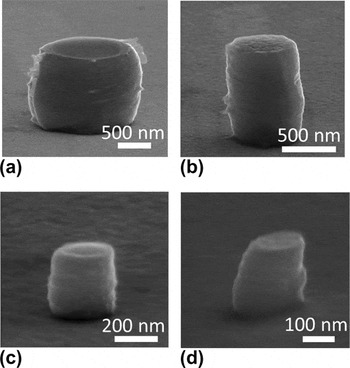
Representative SEM micrographs of as-fabricated and corresponding postmortem zinc pillars for all sizes tested are shown in Figs. 1 and 3, respectively. All zinc pillars in these figures were compressed with engineering strain rate of ∼10−3 s−1. In these structures, no distinct crystallographic shear offsets are observed, and slip lines are not obvious on the pillar surfaces. Instead, the zinc material is displaced laterally during uniaxial compression, and the resulting structure resembles a barrel shape. Horizontal striations and material folding are observed on the zinc pillar sidewalls. These postcompression SEM images also reveal that the majority of barreled zinc pillars have the largest diameter near the midpoint of the deformed pillar. The barreled pillar diameter tapers off close to the contact surfaces of the nanoindenter tip and substrate where mechanical constraint is expected to be the greatest. The lack of distinct crystalline deformation features may indicate there are a large number of active slip systems in these specimens, which allows the deformation to spread more evenly throughout the sample volume. This is not entirely surprising as zinc has a much lower melting temperature than HCP magnesium or titanium, thus, more slip systems may be thermally activated at room temperature.
Representative SEM micrographs of zinc pillars after deformation with diameters of (a) 1060 nm, (b) 550 nm, (c) 230 nm, and (d) 130 nm. Note the postmortem pillars shown here are the same as those as-fabricated pillars shown in Fig. 1. All SEM images are taken at a 70° stage tilt.

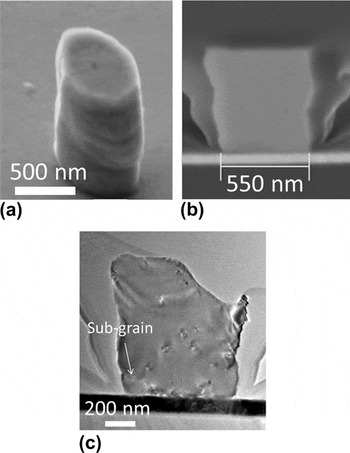
To further reveal the deformation mechanisms operating in zinc submicron structures fabricated in this work, compressed specimens were inspected by FIB cross-sectioning and TEM analysis. Figure 4(a) shows a 550-nm diameter zinc pillar, which exhibited barrel deformation with the pillar diameter increasing throughout the height of column. An SEM micrograph of the FIB cross-section of the same pillar, shown in Fig. 4(b), indicates that the pillar is fully dense and does not contain any observable internal voids. In addition, it does not show any plastic deformation of the titanium and gold layers beneath the pillar. This indicates the yield strength of the seed layer is greater than the zinc pillar. Interestingly, bright-field TEM imaging, shown in Fig. 4(c), reveals that despite this zinc pillar having been deformed by approximately 20% engineering strain, there is again no evidence of distinct crystallographic shear offsets, twin bands, or crystal rotations within the specimen. Note that the top right corner of this particular pillar was unintentionally ion-milled away during the FIB thinning process. Inspection of the zone axes across the width of this zinc pillar confirmed there is no change in crystalline orientation. This indicates that the pillar remains single crystalline even after the gross deformation. A small subgrain may have developed at the bottom left corner of the pillar during deformation, which may indicate a highly stressed region. Additional isolated dislocation defects are identified within the deformed pillar. Identical FIB and TEM analyses were repeated on other compressed zinc pillars (not shown) and revealed similar results: the deformed structure remains single crystal after deformation and with small subgrain formation at highly strained regions. In addition, no distinct twin boundaries or slip bands were observed. An approximate dislocation density of the deformed sample was measured from the TEM micrographs to be ∼4 × 10¹³/m2.
Postcompression electron microscopy analysis of a 550 nm diameter zinc pillar. SEM images of the (a) compressed pillar and (b) FIB cross-section are shown. A bright-field TEM image of the deformed and cross-sectioned pillar is shown in (c). Note that for the TEM image shown in (c), additional FIB thinning during sample preparation caused the top right corner of the pillar to be slightly milled away.

The TEM micrographs indicated the absence of twin boundaries in the compressed zinc pillars. This suggests that the small-scale deformation mechanisms operating in zinc may be different from bulk where twinning is often observed.Reference Antonopoulos, Karakostas, Komninou and Delavignette43 However, this is consistent with microstructure results reported by Byer et al.Reference Byer, Li, Cao and Ramesh21 and Lilleodden,Reference Lilleodden20 where no twin boundary formation was observed during the uniaxial compression of [0001] magnesium columnar microstructures. However, twinning was observed by Kim et al.Reference Kim, Yi, Huang, Lilleodden, Lou, Lilleodden, Boyce, Lu, Derlet, Weygand, Li, Uchic and Le Bourhis22 in compressed < > magnesium pillars. Ye et al.Reference Ye, Mishra, Sachdev and Minor25 also reported twin deformations during the in situ TEM compression tests of small magnesium structures. The contrasting reported magnesium pillar compression results may suggest that size-dependent twin boundary deformation mechanisms may be affected by the pillar crystallographic orientation.
C. Stress–strain behavior of zinc pillars
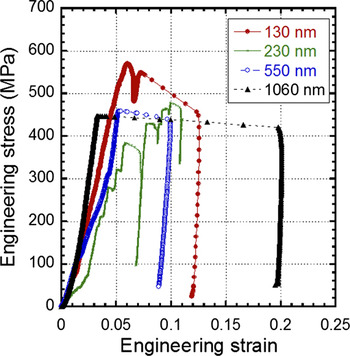
Representative engineering stress–strain curves collected from the uniaxial compression of zinc pillars are shown in Fig. 5. The stress–strain curves of all zinc pillar sizes are populated by discrete and stochastic strain bursts. Such deformation behavior was also observed during uniaxial compression of small titanium alloy structures. Yu et al.Reference Yu, Shan, Li, Huang, Xiao, Sun and Ma23 demonstrated the stress–strain curves of micron scale titanium alloy pillars exhibit strain bursts associated with the twinning process. On the other hand, strain bursts do not occur for titanium alloy specimens with sizes smaller than 700 nm, where deformation is driven only by ordinary dislocation plasticity and without twin boundary formation. Interestingly, the strain bursts, which populate the stress–strain curves of titanium alloy and zinc pillars are quite similar, yet no twin boundary formation was observed in the compressed zinc pillars. However, the lack of twin bands in the deformed zinc pillars, see Fig. 4, may indicate the strain bursts are not associated with twinning. Another possible explanation of strain bursts may be due to dislocation nucleation or multiplication processes which can also lead to softening of the pillar.
Representative engineering stress–strain curves of 1060-nm, 550-nm, 230-nm, and 130-nm diameter zinc pillars.

D. Effects of aspect ratios, strain rate, and size on zinc pillars
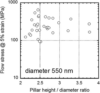
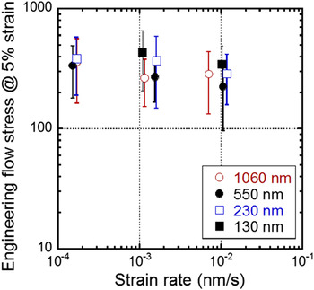
To demonstrate that the observed strengths are not affected by the pillar heights, the measured flow stresses of 550-nm diameter pillars at 5.0% engineering strain is plotted as a function of the specimen aspect ratio in Fig. 6. The measurement of flow stress at 5.0% strain is necessary due to the ambiguous yield point at small deformations during the microcompression tests. In addition, flow stresses extracted at higher strain values may be affected by the changes of sample geometry from cylindrical to barrel shape. Results from Fig. 6 show the sample strengths do not vary significantly with the aspect ratios of the pillar. The influence of strain rate on the engineering flow stress for zinc pillars is displayed in Fig. 7. No significant change is observed in the mechanical strength of small-scale zinc specimens with the strain rate. This is in contrast with the deformation behaviors of bulk zinc specimens where a stress exponent value of 8.7 is reported.Reference Adams, Blish and Vreeland35 The different strain rate responses between the bulk and submicron scale pillar specimens again suggest the deformation mechanisms of zinc may be size dependent.
Plot of 550 nm diameter zinc pillar engineering flow stresses measured at 5.0% strain as a function of specimen aspect ratio (height/diameter).

Plot of zinc pillar engineering flow stresses measured at 5.0% strain as a function of engineering strain rate for deformed zinc pillars.

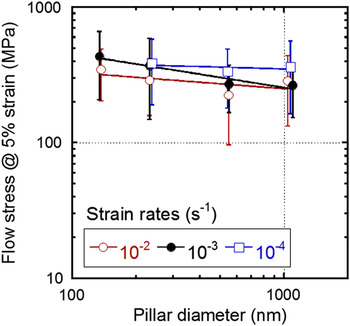
The mechanical strength dependence on diameter for zinc pillars is summarized in Fig. 8. Results from 10−2, 10−3, and 10−4 s−1 strain rates are included with power law-fitted trend lines. The error bars correspond to a data spread of one standard deviation. Even though the trend lines for data obtained with strain rate of 10−3 s−1 may suggest a small increase in the flow stresses with the reduction of pillar size, the mechanical strengths measured are statistically indistinguishable from each other due to the wide scattering of data. Therefore, it appears the strength of submicron zinc pillars is insensitive to the sample dimensions. The average flow stress values are in the range of approximately 226–431 MPa. It is important to note that the average flow stresses exhibited by these zinc pillars are much greater than the 5% strain flow stress of bulk zinc single crystals which are in the range of ∼1.63Reference Gilman44–3.14 MPa,Reference Kawada45 but still far from the theoretical strength for this material. The lack of size effects shown in this work appears to contradict with results from other HCP materials, such as magnesiumReference Lilleodden20, Reference Ye, Mishra, Sachdev and Minor25 and titanium,Reference Sun, Guo, Yao, Xiao, Greer and Sun24 as well as the majority of studies on the small-scale mechanical properties of single-crystalline metals.Reference Uchic, Shade and Dimiduk1–Reference Greer and De Hosson3 However, our results are consistent with Byer et al.Reference Byer, Li, Cao and Ramesh21 who also reported no observable strength size effects for [0001] oriented magnesium pillars with diameters between 2.5 um and 10 um. Yu et al.Reference Yu, Shan, Li, Huang, Xiao, Sun and Ma23 also reported the strength of titanium alloy pillars is not sensitive to size and approaches the theoretical values of titanium for sizes near 0.7 μm and smaller. In contrast, the mechanical strengths of zinc submicron structures studied here only reach a fraction of the theoretical value.
Plot of engineering flow stresses measured at 5.0% strain as a function of zinc pillar diameter.

One of the possible explanations for the lack of strength size effect in the submicron scale zinc structures may be related to the amount of preexisting defects in them. Bei et al.Reference Bei, Shim, Pharr and George28 demonstrated that the mechanical strengths of molybdenum alloy are size independent if the specimens are either pristine or severely prestrained. They show the pristine submicron pillars have strength near the theoretical values while the severely prestrained molybdenum samples are soft like bulk. Since the as-fabricated zinc pillars contain preexisting dislocation with density of 1.5 × 10¹³/m2, see TEM micrographs in Fig. 2, and the strength of the material is not sensitive to the specimen dimension, this leads us to hypothesize that the initial defect concentrations in the zinc structures are above a critical limit such that dislocation starvation state was not achieved during uniaxial compression experiments. This is further confirmed by the TEM images of the deformed pillars (see Fig. 4), which suggest the presence of residual dislocation defects in the compressed zinc structures. In fact, careful inspection of the micrographs of as-fabricated zinc pillars show the defect density within the structures can be quite dense with spacing between individual defects on the order of 100 nm. This indicates that even the smallest specimens produced in this work will have a high probability to contain preexisting defects prior to the compression experiments. Therefore, the mechanical strength of zinc pillars will correspond to the flow stresses required to activate dislocation motion rather than nucleating new dislocations. Hence, the pillar strength is expected to be close to the bulk value rather than the theoretical strength.
IV. CONCLUSIONS
In conclusion, columnar zinc submicron structures with average diameters between 130 and 1060 nm were fabricated using electron beam lithography and electroplating techniques. These specimens were subsequently tested by uniaxial microcompression methods in a nanoindenter outfitted with a flat diamond tip. TEM analysis of as-fabricated specimens revealed that the pillars are generally single-crystalline and contain initial dislocation densities of ∼ 1.5 × 10¹³/m2. These zinc structures also have a preferred out-of-plane orientation close to the [0001] direction. Postcompression analysis by TEM revealed no twin boundary formation in the deformed structures. This may indicate the twinning process in zinc structures may be size dependent, with a lower sample size limit beneath which deformation occurs by dislocation plasticity. In addition, compression test results show the zinc pillar mechanical strength is not size dependent and is insensitive to strain rate. This may be due to a high concentration of preexisting dislocation defects within all of the as-fabricated structures.
ACKNOWLEDGMENTS
T.Y. Tsui thanks Canadian NSERC Discovery, NSERC Research Tools and Instruments, and the Canada Foundation for Innovation (CFI) for the support of this research. The authors thank Dr. Aju Jugessur and Edward Xu for assistance with operation of the Leica EBPG5000+ electron beam lithography system and gratefully acknowledge critical support and infrastructure provided for this work by the Emerging Communications Technology Institute at the University of Toronto. The transmission electron microscopy analysis described in this paper was performed at the Canadian Center for Electron Microscopy (CCEM), which is operated by the Brockhouse Institute for Materials Research of McMaster University. The CCEM is supported by NSERC and other government agencies. T.Y. Tsui would like to thank Professor Joost Vlassak for valuable discussions.