1. Introduction
Over thirty years ago, in a highly cited paper in the Journal of Fluid Mechanics, Park & Homsy (Reference Park and Homsy1984) derived the pressure jump across the moving interface between two fluids confined in a Hele-Shaw cell using double asymptotic methods. This result has since been widely applied in the description of moving menisci in confined media. Relevant phenomena include various viscous fingering situations (Bensimon et al. Reference Bensimon, Kadanoff, Liang, Shraiman and Tang1986; Geoffroy et al. Reference Geoffroy, Plouraboué, Prat and Amyot2006), the Kelvin–Helmholtz instability (Gondret & Rabaud Reference Gondret and Rabaud1997; Plouraboué & Hinch Reference Plouraboué and Hinch2002) or the printer’s instability between journal bearings (Rabaud, Couder & Michalland Reference Rabaud, Couder and Michalland1991; Rabaud Reference Rabaud1994). Using simpler techniques, Paterson (Reference Paterson1996) obtained the static version of the result of Park & Homsy (Reference Park and Homsy1984), as well as a first experimental check by analysing the shapes of menisci distorted by wetting defects in Hele-Shaw cells (Paterson, Fermigier & Limat Reference Paterson, Fermigier, Jenffer and Limat1995).
A huge number of papers in the literature describe the shapes of menisci confined between particles and the forces they exert. The importance of these small confined liquid drops is obvious when building sand castles at the beach, as the strong cohesion of the grains is caused by the minute amounts of liquid between the grains. The forces exerted by capillary bridges often dominate the cohesion and mechanical behaviour of powders, wet soils and granular materials in general (Mitarai & Nori Reference Mitarai and Nori2006). They strongly affect the adhesion or friction between solid particles or surfaces and consequently have a huge practical impact in many small-scale applications (Butt & Kappl Reference Butt and Kappl2009). The precision of dip-pen nanolithography techniques, for instance, depends on the static and dynamic properties of capillary bridges between an atomic force microscope tip and the printed surface (Eichelsdoerfer, Brown & Mirkin Reference Eichelsdoerfer, Brown and Mirkin2014). The presence of liquid interfaces during the fabrication process of microstructures can lead to their collapse and ruin (Roman & Bico Reference Roman and Bico2010). The adhesion of some insects relies partially on the presence and control of capillary bridges formed by a viscous secretion between their leg pads and environing surfaces (Federle et al. Reference Federle, Riehle, Curtis and Full2002). In all of these applications, the static forces and shapes of liquid menisci are crucial. Their dynamic properties also often play a dominant role in the macroscopic mechanical behaviour of materials or animals.
In this paper, we start by giving a simple derivation of the outcome of the work by Park & Homsy (Reference Park and Homsy1984) in the particular static case. Building on this result, we compute higher-order terms in the development of
 ${\rm\Delta}P$
in terms of
 $h/R$
, where
 $2h$
is the thickness of the Hele-Shaw cell and
 $R$
is the interface radius of curvature in the plane of the confining walls. We then use the first-order approximation to determine the shapes of capillary bridges connecting a plane wall and a cylindrical boundary. We compare analytical predictions and numerical solutions of the model with experimentally measured shapes.
2. Pressure drop across a static interface in a Hele-Shaw geometry
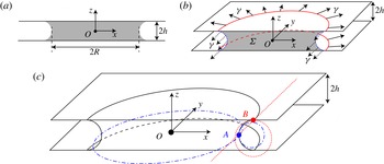
We consider a circular puck of liquid bridging the parallel plates of a Hele-Shaw cell, as shown in figure 1(a), and assume that the liquid is totally wetting the walls. As discussed, for instance, by de Gennes (Reference de Gennes1985), Ajaev & Homsy (Reference Ajaev and Homsy2006) and Bonn et al. (Reference Bonn, Eggers, Indekeu, Meunier and Rolley2009), this means that the air/liquid interface of the drop connects to a liquid film adsorbed on the plates around the drop. The thickness of this layer is usually up to 100 nm, at least three orders of magnitude smaller than the wall separation of the Hele-Shaw cells considered here. The region where the air/liquid interface connects to this microscopic film is commonly called the ‘apparent’ contact line, and will in the following be considered as the boundary of the capillary bridges we consider.
(a) Side view of a circular liquid drop of equatorial radius
 $R$
bridging two parallel glass plates separated by a gap of thickness
 $2h$
;
 $O$
is the centre of the drop. (b) We consider the mechanical equilibrium of the half of the drop located in the
 $y>0$
half-space. The pressure difference
 ${\rm\Delta}P$
applies on the surface area
 ${\it\Sigma}$
of the drop cross-section, the light grey area in the sketch. Surface tension forces pull on the bounding lines with an intensity
 ${\it\gamma}$
per unit length. Contributions from the apparent contact lines are sketched using full arrows, while forces associated with lateral menisci are shown as dotted arrows. (c) Cross-section of the drop through a vertical symmetry plane. The osculating circles are sketched to show the principal radii of curvature of the interface at points
 $A$
along the equator of the drop (dash-dotted lines) and
 $B$
at the apparent contact line (dotted lines).

The capillary pressure inside the drop is given by the Laplace law (de Gennes, Brochard-Wyart & Quéré Reference de Gennes, Brochard-Wyart and Quéré2004):
 $$\begin{eqnarray}{\rm\Delta}P={\it\gamma}\left(\frac{1}{R_{1}}+\frac{1}{R_{2}}\right),\end{eqnarray}$$
where
 ${\it\gamma}$
is the surface tension of the liquid, and
 $R_{1}$
and
 $R_{2}$
are the principal radii of curvature of the liquid/air interface. The two natural scales for curvature in this problem are the thickness
 $2h$
of the Hele-Shaw cell, and the radius of curvature
 $R=1/\mathscr{C}$
of the interface in the plane of the plates, measured at mid-height between the walls (
 $z=0$
). While it may be thought that
 $R$
and
 $h$
are the principal radii of curvature of the interface, both quantities are actually coupled and can generally not be identified with
 $R_{1,2}$
.
We now consider the mechanical equilibrium of the half of the drop located in the region
 $y>0$
of space, as shown in figure 1(b). We estimate the projection along the
 $y$
direction of pressure and capillary forces applied on this semidrop. The pressure difference
 ${\rm\Delta}P$
between the inside and outside of the drop applies on the surface area
 ${\it\Sigma}$
of the drop cross-section, represented as the grey area in figure 1(a,b). At first order in
 $h/R$
,
 ${\it\Sigma}\simeq 4(R+h)h-{\rm\pi}h^{2}$
. The pressure force acting along
 $Oy$
is thus
 $$\begin{eqnarray}F_{P}=4hR{\rm\Delta}P\left(1+\left(1-\frac{{\rm\pi}}{4}\right)\frac{h}{R}+O\left(\left(\frac{h}{R}\right)^{2}\right)\right).\end{eqnarray}$$
Surface tension acts at the boundaries of the semidrop, and counterbalances pressure forces to ensure equilibrium. The projected length of the lines normal to
 $Oy$
involves two terms. The first arises from the lines where the liquid/air interface reaches the upper and lower plates, which are semicircles of radius
 $R+h$
at first order in
 $h/R$
. At these apparent contact lines, surface tension pulls on the drop radially, as shown by figure 1(b). The length of these lines is
 $2\times {\rm\pi}(R+h)$
, and their projected length along
 $Ox$
is
 $4(R+h)$
. The corresponding capillary force thus pulls the drop towards the
 $y>0$
region with intensity
 $4{\it\gamma}(R+h)$
. The other place where interfacial forces apply is along the menisci on the sides of the semidrop, the dotted lines in figure 1(b), of length
 $2\times {\rm\pi}h$
. Capillary forces act here towards
 $y<0$
with intensity
 $2{\rm\pi}{\it\gamma}h$
. The total capillary force acting on one half of the drop is thus
 $$\begin{eqnarray}F_{{\it\gamma}}\simeq {\it\gamma}(4R+(4-2{\rm\pi})h),\end{eqnarray}$$
or more precisely
 $$\begin{eqnarray}F_{{\it\gamma}}=4R{\it\gamma}\left(1+\left(1-\frac{{\rm\pi}}{2}\right)\frac{h}{R}+O\left(\left(\frac{h}{R}\right)^{2}\right)\right).\end{eqnarray}$$
At mechanical equilibrium, pressure and capillary forces exactly balance:
 $F_{P}+F_{{\it\gamma}}=0$
. Keeping terms of order up to
 $h/R$
then yields the expected result:
 $$\begin{eqnarray}{\rm\Delta}P=-\frac{{\it\gamma}}{h}\left(1-\frac{{\rm\pi}}{4}\frac{h}{R}+O\left(\left(\frac{h}{R}\right)^{2}\right)\right).\end{eqnarray}$$
2.1. Comments
2.1.1. Energy
The pressure difference across the drop interface can also be derived using energy considerations. Let us first express the volume
 $V$
of a drop as a function of
 $h$
and
 $R$
:
 $$\begin{eqnarray}V=2{\rm\pi}R^{2}h\left(1+(2-{\rm\pi})\frac{h}{R}+O\left(\left(\frac{h}{R}\right)^{2}\right)\right).\end{eqnarray}$$
An infinitesimal change
 $\text{d}V$
in the drop volume corresponds to an increase of the drop radius
 $\text{d}R$
. The work done by pressure forces during this transform is
 $$\begin{eqnarray}{\it\delta}W=-{\rm\Delta}P\,\text{d}V=-{\rm\Delta}P4{\rm\pi}Rh\left(1+\left(1-\frac{{\rm\pi}}{4}\right)\frac{h}{R}+O\left(\left(\frac{h}{R}\right)^{2}\right)\right)\,\text{d}R.\end{eqnarray}$$
The work of pressure forces is converted into surface energy, which arises through two contributions. First, the wetting film around the drop gets partially covered as
 $R$
increases, thus reducing the area of the liquid/air interface. At first order in
 $h/R$
, the surface area
 ${\it\Sigma}_{f}$
of the film covered by the drop is
 $$\begin{eqnarray}{\it\Sigma}_{f}=2\times {\rm\pi}R^{2}\left(1+\frac{h}{R}+O\left(\left(\frac{h}{R}\right)^{2}\right)\right)^{2}.\end{eqnarray}$$
The capillary energy variation corresponding to an increase of
 ${\it\Sigma}_{f}$
is
 $$\begin{eqnarray}\text{d}E_{{\it\gamma}_{f}}=-{\it\gamma}\,\text{d}{\it\Sigma}_{f}=-{\it\gamma}4{\rm\pi}R\left(1+\frac{h}{R}+O\left(\left(\frac{h}{R}\right)^{2}\right)\right)\,\text{d}R.\end{eqnarray}$$
The lateral surface of the drop, of area
 ${\it\Sigma}_{l}\simeq 2{\rm\pi}^{2}Rh$
, increases as the drop is inflated. The related energy change is
 $$\begin{eqnarray}\text{d}E_{{\it\gamma}_{l}}={\it\gamma}\,\text{d}{\it\Sigma}_{l}={\it\gamma}2{\rm\pi}^{2}h\left(1+O\left(\frac{h}{R}\right)\right)\,\text{d}R.\end{eqnarray}$$
Equating the pressure work and the surface energy change (
 ${\it\delta}W=\text{d}E_{{\it\gamma}_{f}}+\text{d}E_{{\it\gamma}_{l}}$
) also leads to (2.5).
2.1.2. Interfacial principal curvatures
The shape of a static drop confined between parallel walls is thus that of a Delaunay surface (Delaunay Reference Delaunay1841), i.e. a surface of revolution with constant mean curvature
 ${\it\kappa}$
:
 $$\begin{eqnarray}{\it\kappa}=\frac{1}{h}-\frac{{\rm\pi}}{4R}.\end{eqnarray}$$
It may be thought that the curvature of the interface in the plane normal to the plates is
 $1/h$
, whereas the curvature in the plane parallel to the plates should be
 $1/R$
. However, as suggested by Nagel, Brun & Gallaire (Reference Nagel, Brun and Gallaire2014), the two contributions do not necessarily reflect the principal radii of curvature of the interface, and (2.11) may be rearranged to better highlight the principal curvatures at different locations on the interface. The intersection of the liquid/air interface with the horizontal mid-height plane
 $Oxy$
is a perfect circle of radius
 $R$
. At a point
 $A$
located on this circle, as defined in figure 1(c), the principal radius of curvature of the interface in the
 $Axy$
plane parallel to the plates is indeed
 $R_{1A}=-R$
. To satisfy (2.11), the transverse curvature is thus
 $1/R_{2A}=1/h+(1-{\rm\pi}/4)/R$
, where
 $R_{2A}<h$
. At point
 $B$
, the interface is not curved in the transverse (
 $Byz$
) plane:
 $R_{1B}=\infty$
. The curvature in the
 $Bxz$
plane is
 $1/R_{2B}={\it\kappa}=1/h-{\rm\pi}/4R$
, with
 $R_{2B}>h$
.
In the special case of a very large drop (
 $R/h\rightarrow +\infty$
), the in-plane and transverse curvatures decouple. Then, the intersection of the drop boundary with a vertical plane is exactly a semicircle of radius
 $h$
, and the pressure in the drop is
 $$\begin{eqnarray}{\rm\Delta}P=-\frac{{\it\gamma}}{h}.\end{eqnarray}$$
2.1.3. The case of partial wetting
Using a similar force or energy balance, one can derive the pressure jump in the case of a partially wetting fluid. We call
 ${\it\theta}$
the contact angle of the fluid on the solid walls. In this case, the pressure jump is
 $$\begin{eqnarray}{\rm\Delta}P=-\frac{2{\it\gamma}}{h}\cos {\it\theta}\left(1-\frac{h}{2R\cos {\it\theta}}\left(\frac{\sin {\it\theta}}{2}+\frac{1}{2\cos {\it\theta}}\left(\frac{{\rm\pi}}{2}-{\it\theta}\right)\right)+O\left(\left(\frac{h}{R}\right)^{2}\right)\right).\end{eqnarray}$$
This equation is in agreement with the interpretation in terms of line tension given in Paterson et al. (Reference Paterson, Fermigier, Jenffer and Limat1995) and Paterson (Reference Paterson1996). The limit of this result in the case of total wetting (
 ${\it\theta}=0$
) is indeed (2.5). In the special case
 ${\it\theta}={\rm\pi}/2$
, the liquid interface is a cylinder of radius
 $R$
and height
 $2h$
, and (2.13) reduces to
 $$\begin{eqnarray}{\rm\Delta}P=\frac{{\it\gamma}}{R}.\end{eqnarray}$$
2.1.4. Higher-order corrections
Equation (2.5) remains a good approximation of the interfacial curvature as long as
 $h/R$
is small. If the bounding plates separate (
 $h$
increases),
 $h/R$
becomes of order unity, and the bridge ruptures at some critical wall separation. In this regime, the first-order development in the pressure (or curvature) most likely fails, and one may need to compute higher-order terms. As shown by Melrose (Reference Melrose1966), it is possible to express analytically the shape of the meniscus using elliptic integrals. Building on the result of Melrose (Reference Melrose1966), one can develop the constant curvature
 ${\it\kappa}$
of the meniscus as a power series in
 $h/R$
. This is done through an iterative process, and yields the first terms of the development:
 $$\begin{eqnarray}\displaystyle {\it\kappa} & = & \displaystyle \frac{1}{h}\left[1-\frac{{\rm\pi}}{4}\frac{h}{R}+\left(\frac{{\rm\pi}}{4}-\frac{{\rm\pi}^{2}}{32}\right)\left(\frac{h}{R}\right)^{2}-\left(\frac{9{\rm\pi}}{32}-\frac{{\rm\pi}^{2}}{8}+\frac{5{\rm\pi}^{3}}{512}\right)\left(\frac{h}{R}\right)^{3}\right.\nonumber\\ \displaystyle & & \displaystyle \left.+\,\left(\frac{11{\rm\pi}}{32}-\frac{21{\rm\pi}^{2}}{64}+\frac{35{\rm\pi}^{3}}{512}-\frac{{\rm\pi}^{4}}{256}\right)\left(\frac{h}{R}\right)^{4}+O\left(\left(\frac{h}{R}\right)^{5}\right)\right].\end{eqnarray}$$
The appendix A at the end of the paper gives the main steps to compute the curvature at an arbitrary order in
 $h/R$
.
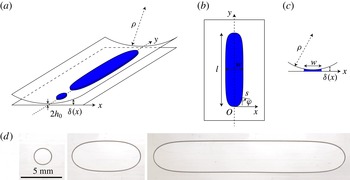
(a) Capillary bridges between a planar surface and a cylinder of radius
 ${\it\rho}$
with a horizontal axis. The gap between the walls at a distance
 $x$
from the line of closest gap is approximately
 ${\it\delta}(x)=2h_{0}+x^{2}/2{\it\rho}$
. (b) Top view, parametrization of the drop profile. The curvilinear coordinate
 $s$
is the distance to the extremity of the drop measured along its contour. The normal to the boundary in the horizontal plane makes an angle
 ${\it\varphi}$
with the
 $Oy$
axis. Here,
 $l$
is the length of the drop and
 $w$
is its width, measured at the apparent contact line. (c) Side view of the capillary bridge. (d) Bottom view of drops of silicone oil trapped between a glass plate and a glass cylinder lying horizontally. The drops are seen from below, through the horizontal glass plane. The radius
 ${\it\rho}$
of the cylinder is 70 mm and the minimal gap
 $h_{0}=244~{\rm\mu}\text{m}$
. Small droplets adopt a circular shape. As the volume of oil increases, drops are observed to stretch along the cylinder axis, where the gap is smallest. The drop width saturates to a finite value
 $w^{\ast }\simeq 3.4~\text{mm}$
.

3. Shape of a drop between a plane and a horizontal cylinder
3.1. Experiments
We now apply the result of (2.11) to derive the shape of a liquid volume connecting a horizontal plane and a cylinder. Such elongated capillary bridges may in practice be found between journal bearings (Rabaud et al.
Reference Rabaud, Couder and Michalland1991; Rabaud Reference Rabaud1994) or along small worms crawling on moist surfaces (Sauvage et al.
Reference Sauvage, Argentina, Drappier, Senden, Siméon and Di Meglio2011). The experimental set-up is shown in figure 2(a–c). We introduce a drop of silicone oil between a horizontal glass plate and a surmounting cylinder made of glass or Plexiglas. Thin plastic or glass spacers separate the plane and the cylinder. The axis of the cylinder is horizontal, so that the thickness
 ${\it\delta}$
of the gap increases approximately quadratically with the distance
 $x$
from the line of closest gap:
 ${\it\delta}(x)\simeq 2h_{0}+x^{2}/(2{\it\rho})$
, where
 $2h_{0}$
is the minimal thickness and
 ${\it\rho}$
is the radius of curvature of the upper cylindrical wall. In our experiments,
 $h_{0}$
is of order
 $100~{\rm\mu}\text{m}$
while
 ${\it\rho}\sim 5~\text{cm}$
. The gap thickness is small enough and the set-up is horizontal so that gravity has a negligible effect on the shapes of drops. We introduce a liquid bridge of totally wetting silicone oil between the facing walls. The drop tends to get trapped in the region with the smallest gap, along the axis of the cylinder, where the solid/liquid contact area is largest for a given volume. We image these drops through the bottom glass plate from below using a digital SLR camera. As revealed by figure 2(d), small droplets remain circular and form a puck, whereas larger liquid volumes stretch along the shallow region. The width
 $w$
of large drops saturates to an asymptotic value
 $w^{\ast }$
that depends on
 ${\it\rho}$
and
 $h_{0}$
. We observe that
 $w^{\ast }$
is typically a few millimetres.
3.2. Theoretical prediction of the shape
In the absence of gravity, the interplay between the in-plane curvature and the height of the gap sets the shape of the drop. In a static situation, the pressure in the drop is constant, so that the position of the air–liquid interface is given by (2.11) with
 ${\it\kappa}$
being a constant that depends on the volume of the drop. The gap thickness is given by
 ${\it\delta}(x)=2h_{0}+x^{2}/2{\it\rho}$
, where
 $2h_{0}$
is the minimal thickness and
 ${\it\rho}$
is the radius of curvature of the upper cylindrical wall. As shown in figure 2(b), the distance to one extremity of the drop along the contour is the curvilinear coordinate
 $s$
, and the local orientation of the interface in the plane of the plates is defined by the angle
 ${\it\varphi}$
, so that the curvature of the projected shape in the
 $Oxy$
plane is
 $1/R=\text{d}{\it\varphi}/\text{d}s$
. The shape of the drop in the plane of the plates is thus given by
 $$\begin{eqnarray}{\it\kappa}=\frac{2}{{\it\delta}(x)}-\frac{{\rm\pi}}{4}\frac{\text{d}{\it\varphi}}{\text{d}s}.\end{eqnarray}$$
We take one extremity of the drop as a reference point:
 ${\it\varphi}=0$
,
 $s=0$
. Since
 ${\it\kappa}$
is constant, we have
 $$\begin{eqnarray}\frac{2}{{\it\delta}(x)}-\frac{{\rm\pi}}{4}\frac{\text{d}{\it\varphi}}{\text{d}s}=\frac{1}{h_{0}}-\frac{{\rm\pi}}{4}\frac{\text{d}{\it\varphi}}{\text{d}s}(s=0)\end{eqnarray}$$
or, noting that
 $\text{d}{\it\varphi}/\text{d}s~(s=0)=\mathscr{C}_{0}$
,
 $$\begin{eqnarray}\frac{\text{d}{\it\varphi}}{\text{d}s}=\mathscr{C}_{0}+\frac{8}{{\rm\pi}}\frac{1}{2h_{0}+x^{2}/2{\it\rho}}-\frac{4}{{\rm\pi}h_{0}}.\end{eqnarray}$$
The choice of
 $\mathscr{C}_{0}$
then enables one to integrate (3.3). For given values of
 $h_{0}$
and
 ${\it\rho}$
, the value of
 $\mathscr{C}_{0}$
sets the length or volume of the drop, and uniquely determines its shape. A similar approach was used by Paterson (Reference Paterson1996) to solve the shape of a meniscus in a vertical Hele-Shaw cell of constant gap in which the deformations of interfaces are imposed by gravity instead of confinement gradients.
To compare the prediction of the model with the experimental shapes of the drops, we solve (3.3) numerically using Matlab. We select the value of the curvature
 $\mathscr{C}_{0}$
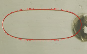
such that the length of the computed profile matches that of the experiment. Figure 3 compares the experimentally measured boundary of an elongated drop with the prediction of the numerics, showing an excellent match of the shapes all along the drop boundary. If one neglects the coupling between the in-plane and transverse curvatures, assuming
 ${\it\kappa}=1/h-1/R$
, equation (3.3) is changed to
 $$\begin{eqnarray}\frac{\text{d}{\it\varphi}}{\text{d}s}=\mathscr{C}_{0}+\frac{2}{2h_{0}+x^{2}/2{\it\rho}}-\frac{1}{h_{0}}.\end{eqnarray}$$
The numerical solution of (3.4) matching the experimentally measured drop length is also shown in figure 3. It does not match the experimental data as well and overestimates the width of elongated drops by approximately 8 %. As a comparison, the apparent thickness of the drop boundary due to the meniscus radius of curvature is at first order equal to one half of the gap thickness. As
 ${\it\delta}$
is typically only approximately 1 % of the drop width, it does not perturb the accuracy of the comparison of the model and experiment.
Top view of an elongated drop between a plane and a cylinder. The minimal gap and the radius of the cylinder are
 $2h_{0}=295~{\rm\mu}\text{m}$
and
 ${\it\rho}=70~\text{mm}$
. We superimpose the experimental profile with the numerical solution of (3.3) (continuous line). They are in excellent agreement. The dashed line is the profile computed using (3.4) neglecting the coupling between the two terms in the curvature, i.e. assuming that the curvature of the interface is
 ${\it\kappa}=2/{\it\delta}(x)-1/R$
. The latter profile does not match the experimental one as well as the prediction of (3.3). The apparent thickness of the drop boundary is equal to the radius of curvature of the meniscus, which at first order is one half of the gap thickness
 ${\it\delta}$
. The accuracy of the comparison with our model in not affected by the finite line thickness as the boundary appears to be sharp enough.

3.3. Width of large drops
Large drops stretch along the region of smallest gap, and their width saturates to a value
 $w^{\ast }$
, measured at the apparent contact line. We follow the derivation of § 2 to express
 $w^{\ast }$
as a function of
 $h_{0}$
and
 ${\it\rho}$
. We consider the mechanical equilibrium of one half of a very long drop, and calculate the forces applied in the
 $y$
direction along the length of the drop. In the vicinity of the middle of the drop, the oil/air boundary in the plane of the plates is close to a straight line, so that the curvature of the interface is simply
 $2/{\it\delta}^{\ast }$
, where
 ${\it\delta}^{\ast }$
is the thickest gap explored by the drop. The pressure inside the drop is thus
 ${\rm\Delta}P=2{\it\gamma}/{\it\delta}^{\ast }$
. The pressure force acting on one half of the drop is
 ${\rm\Delta}P$
multiplied by the area of the cross-section of the drop in its central region:
 $$\begin{eqnarray}F_{P}=\frac{2{\it\gamma}}{{\it\delta}^{\ast }}\left[2\int _{0}^{w^{\ast }/2}{\it\delta}(x)\,\text{d}x-\frac{{\rm\pi}}{4}{{\it\delta}^{\ast }}^{2}\right]\end{eqnarray}$$
or
 $$\begin{eqnarray}F_{P}=\frac{2{\it\gamma}}{2h_{0}+\displaystyle \frac{{w^{\ast }}^{2}}{8{\it\rho}}}\left[2\int _{0}^{w^{\ast }/2}\left(2h_{0}+\frac{x^{2}}{2{\it\rho}}\right)\,\text{d}x-\frac{{\rm\pi}}{4}\left(2h_{0}+\frac{{w^{\ast }}^{2}}{8{\it\rho}}\right)^{2}\right].\end{eqnarray}$$
Pressure forces are balanced by surface tension. As derived in § 2 above, the projected length of the lines normal to
 $Oy$
where surface tension acts involves two terms. The projection along
 $Ox$
of the lines where the drop reaches the solid has length
 $2w^{\ast }$
. The length of the menisci on the side of the drop is
 ${\rm\pi}{\it\delta}^{\ast }$
. The resulting capillary force is thus
 $$\begin{eqnarray}F_{{\it\gamma}}={\it\gamma}\left(2w^{\ast }-{\rm\pi}\left(2h_{0}+\frac{{w^{\ast }}^{2}}{8{\it\rho}}\right)\right).\end{eqnarray}$$
The balance of capillary and pressure forces now reads
 $$\begin{eqnarray}2w^{\ast }-2{\rm\pi}h_{0}-{\rm\pi}\frac{{w^{\ast }}^{2}}{8{\it\rho}}=\frac{2}{\displaystyle 2h_{0}+\frac{{w^{\ast }}^{2}}{8{\it\rho}}}\left[2h_{0}w^{\ast }+\frac{{w^{\ast }}^{3}}{24{\it\rho}}-{\rm\pi}h_{0}^{2}-\frac{{\rm\pi}{w^{\ast }}^{4}}{256{\it\rho}^{2}}-\frac{{\rm\pi}{w^{\ast }}^{2}h_{0}}{8{\it\rho}}\right].\end{eqnarray}$$
Using the fact that
 ${\it\rho}\gg w^{\ast }\gg h_{0}$
and keeping the largest terms gives the asymptotic width
 $w^{\ast }$
of elongated drops:
 $$\begin{eqnarray}w^{\ast }=(12{\rm\pi}h_{0}^{2}{\it\rho})^{1/3}.\end{eqnarray}$$
The saturation of
 $w$
also implies the existence of an asymptotic value
 $\mathscr{C}_{0}^{\ast }$
of the extremal in-plane curvature
 $\mathscr{C}_{0}$
for large drops. Using (3.3) we obtain
 $$\begin{eqnarray}\mathscr{C}_{0}^{\ast }=\frac{4}{{\rm\pi}}\left(\frac{1}{h_{0}}-\frac{2}{\displaystyle 2h_{0}+\frac{{w^{\ast }}^{2}}{8{\it\rho}}}\right).\end{eqnarray}$$
Combining with the result of (3.9), and in the limit
 $h_{0}\ll {\it\rho}$
, one finds the minimal value of
 $\mathscr{C}_{0}$
for a given geometry:
 $$\begin{eqnarray}\mathscr{C}_{0}^{\ast }\simeq \left(\frac{9}{4{\rm\pi}h_{0}^{2}{\it\rho}}\right)^{1/3},\end{eqnarray}$$
so that
 $$\begin{eqnarray}w^{\ast }\mathscr{C}_{0}^{\ast }=3.\end{eqnarray}$$
The scaling results in (3.9) and (3.11) may also be derived in a simpler way, invoking the constant interfacial curvature. In the central part of long drops, the gap thickness is
 ${\it\delta}^{\ast }=2h_{0}+{w^{\ast }}^{2}/8{\it\rho}$
, and the curvature of the interface is
 ${\it\kappa}^{\ast }=2/{\it\delta}^{\ast }$
. The observed orders of magnitude for
 $h_{0}$
,
 ${\it\rho}$
and
 $w^{\ast }$
are such that
 $h_{0}\gg {w^{\ast }}^{2}/{\it\rho}$
, so that
 $$\begin{eqnarray}{\it\kappa}^{\ast }\simeq \frac{1}{h_{0}}-\frac{{w^{\ast }}^{2}}{16{\it\rho}h_{0}^{2}}.\end{eqnarray}$$
At the end caps, the curvature of the drop is
 $$\begin{eqnarray}{\it\kappa}^{\ast }=\frac{1}{h_{0}}-\mathscr{C}_{0}^{\ast }.\end{eqnarray}$$
Assuming that there is only one characteristic length scale
 $w^{\ast }$
to describe the in-plane shape of drops, one necessarily has
 $\mathscr{C}_{0}^{\ast }w^{\ast }\sim 1$
. Using this last result and combining (3.13) and (3.14), one indeed obtains
 $$\begin{eqnarray}w^{\ast }\sim (h_{0}^{2}{\it\rho})^{1/3}.\end{eqnarray}$$
Figure 4(a) compares the measured value of the width of long drops with the theoretical result of (3.9). Both experimental (
 $w_{exp}^{\ast }$
) and numerical (
 $w_{num}^{\ast }$
) results are in close agreement with the prediction
 $w^{\ast }$
. As tested on a few numerical cases, if one neglects the coupling of in-plane and transverse interfacial curvatures, one overestimates the asymptotic drop width by approximately 8 %, which does not describe the experimental results as well. The numerically determined asymptotic value
 $\mathscr{C}_{0\,num}^{\ast }$
of the curvature at one extremity of long drops is also in excellent agreement with the theoretical expression of
 $\mathscr{C}_{0}^{\ast }$
.
(a) Experimental (
 $w_{exp}^{\ast }$
,

 $w_{num}^{\ast }$
,

 $w^{\ast }$
of (3.9). The equation of the continuous line is
 $w_{exp}^{\ast }=w^{\ast }$
. The equation of the dash-dotted line is
 $w_{num}^{\ast }=1.084w^{\ast }$
, as numerically computed using (3.4); this prediction slightly overestimates our experimental results. We also plot the numerical asymptotic value of the minimal in-plane curvature (
 $\mathscr{C}_{0num}^{\ast }$
,

 $\mathscr{C}_{0}^{\ast }$
of (3.11). (b) The dimensionless width
 $W=w/w^{\ast }$
of drops as a function of their dimensionless length
 $L=l/w^{\ast }$
. The numerical results are shown as full dots (


 $h_{0}$
range from 30 to
 $500~{\rm\mu}\text{m}$
while
 $20<{\it\rho}<70~\text{mm}$
. Small drops are circular (
 $W\simeq L$
) while large drops (
 $L\gg 1$
) elongate and their width saturates to the asymptotic limit
 $W=1$
. The slope of the full line corresponds to a linear variation of
 $W$
with
 $L$
.

Using the result of (3.9), we define the dimensionless width and length of drops,
 $W=w/w^{\ast }$
and
 $L=l/w^{\ast }$
. Plotting
 $W$
as a function of
 $L$
in figure 4(b), we see that numerical and experimental data for various values of
 $h_{0}$
and
 ${\it\rho}$
collapse onto a single master curve. Small drops (
 $W$
,
 $L\ll 1$
) do not explore the gradient of confinement and remain trapped in a region of almost constant gap:
 ${\it\delta}\simeq 2h_{0}$
. As a consequence, their shape is close to circular:
 $W\simeq L$
. Conversely, under the effect of inhomogeneous confinement, larger drops stretch along the axis of the cylindrical wall:
 $L\rightarrow +\infty$
,
 $W\rightarrow 1$
.
4. Conclusion
We have described experimentally and theoretically the shapes of drops trapped between two inhomogeneously spaced walls, a plane and a horizontal cylinder. A simple model predicts accurately the contours of these menisci. We have shown that the shape of such capillary bridges between closely spaced walls is indeed sensitive to the correction given by Park & Homsy (Reference Park and Homsy1984). The correct description of other experimental results on two-phase flows in Hele-Shaw geometries involves the coupling of in-plane and transverse interfacial curvatures. Many dynamical situations with a confined moving curved front should take this effect into account. This is, for instance, the case for all problems related to the Saffman and Taylor viscous fingering instability (Saffman & Taylor Reference Saffman and Taylor1958). Limat (Reference Limat1992), for instance, studied the dynamics of a moving front in a Hele-Shaw cell perturbed by an isolated wettability defect. More recently, Al-Housseiny, Tsai & Stone (Reference Al-Housseiny, Tsai and Stone2012) have described the modified fingering instability in Hele-Shaw cells with a confinement gradient along the flow direction. Anjos & Miranda (Reference Anjos and Miranda2014) have proposed a theoretical description of the fingering instability in a cell whose thickness may evolve in time. In these dynamical situations, it is however likely that observation of the correction of Park & Homsy (Reference Park and Homsy1984) experimentally will be challenging, as the behaviour of moving contact lines is itself not very well understood.
Acknowledgements
I would like to warmly thank G. M. Homsy for his kind advice and suggestions on this project, and L. Limat for interesting discussions and his enthusiastic encouragement. This research has been funded by the Interuniversity Attraction Poles Programme (IAP 7/38 MicroMAST) initiated by the Belgian Science Policy Office.
Appendix A
In § 2, we give the first terms of the development of the curvature
 ${\it\kappa}$
of the surface of a drop of totally wetting liquid connecting two parallel plates separated by a gap of thickness
 $2h$
. In this appendix, following the work of Melrose (Reference Melrose1966), we give the main steps leading to this result and enabling the computation of terms of any order. Melrose (Reference Melrose1966) shows that the mean curvature
 ${\it\kappa}$
of an axisymmetric capillary bridge between two parallel planes is determined by the implicit equation
 $$\begin{eqnarray}h{\it\kappa}=1+\sqrt{c}K\left(-\frac{1}{c}\right)-\sqrt{c}E\left(-\frac{1}{c}\right),\end{eqnarray}$$
where
 $K$
and
 $E$
are complete elliptic integrals of the first and second kind,
 $c=R^{2}{\it\kappa}^{2}+2R{\it\kappa}$
and
 $R$
is the radius of the drop at mid-height between the walls. We then write
 $h{\it\kappa}$
as a power series in
 $h/R$
:
 $$\begin{eqnarray}h{\it\kappa}=\mathop{\sum }_{n=0}^{+\infty }a_{n}\left(\frac{h}{R}\right)^{n}.\end{eqnarray}$$
By developing the right-hand side of (A 1) and identifying the different orders in
 $h/R$
, one can now compute iteratively the coefficients
 $a_{n}$
for arbitrary values of
 $n$
. The terms up to order
 $(h/R)^{4}$
are given in § 2.