I. INTRODUCTION
Carbon nanotubes, originally discovered by Iijima et al.Reference Harris1–Reference Zhang, Ichihashi, Landree, Nihey and Iijima5 almost two decades ago, have attracted significant interest as reinforcements in various metallic, ceramic, and polymeric matrices due to their unique atomic structure and excellent properties, such as high tensile strength, elastic modulus, low density, high aspect ratio, excellent thermal as well as electrical conductivity.Reference Liao, Tan and Sridhar6–Reference Cho, Kikuchi, Miyazaki, Takagi, Kawasaki and Tsukada14 Carbon nanotube (CNT)/metal nanocomposites have potentially attractive properties, such as high tensile strength, stiffness, excellent wear, and corrosion resistance, which make them potential candidates for structural applications in aerospace and transportation in general.Reference Bakshi, Lahiri and Agarwal15–Reference Kim, Eckert, Menzel, Gemming and Hong21 Most of the investigations focus on CNT/polymer composites because of compatibility and flexibility of CNTs in the polymer matrix aiding the fabrication process.Reference Chu, Jia, Jiang and Li7,Reference Yamanaka, Gonda, Kawasaki, Sakamoto, Mekuchi, Kuno and Tsukada22,Reference Esawi, Morsi, Sayed, Taher and Lanka23 CNT/polymer nanocomposites typically exhibit high interfacial strength between the CNT and the polymer matrix due to the molecular-level interaction.Reference Cha, Kim, Arshad, Mo and Hong24 CNT/metal nanocomposites have attracted less attention due to their inferior mechanical properties and because of the inhomogeneous dispersion of CNTs in the metal matrix, the poor quality of metal-CNT interfaces, and the low relative density of CNT/metal nanocomposites. Few researchers have reported improvement in mechanical and tribological properties of CNT/metal nanocomposites fabricated by conventional powder metallurgy techniques. Cha et al.Reference Cha, Kim, Arshad, Mo and Hong24 have reported a unique method of fabricating CNT/metal nanocomposites by molecular-level mixing (MLM) process followed by spark plasma sintering (SPS) resulting in a uniform dispersion of CNTs in the metal matrix.Reference Cha, Kim, Arshad, Mo and Hong24 CNT/metal nanocomposites sintered from nanocomposite powders prepared by MLM exhibit significant improvement in mechanical properties mainly due to the homogeneous distribution of CNTs within the metal matrix and the strong interfacial bonding between CNTs and the metal matrix.Reference Hwang, Lim, Tiley, Banerjee and Hong25 The process for fabricating CNT/Ni composite powders using MLM consists of four steps.Reference Cha, Kim, Arshad, Mo and Hong24–Reference Kim, Eckert, Liu, Park, Kim and Hong28 First, CNTs produced by thermal chemical vapor deposition (CVD) are dispersed in ethanol to make a stable suspension by functionalizing the CNT surfaces. The electrostatic repulsive force between the CNTs overcomes the van der Waals' force to obtain a stable suspension within the solvent due to functionalization of CNTs. Second, a salt containing Ni ions is dissolved in the CNT suspension. Additional ultrasonication helps the dispersion of Ni ions among the suspended CNTs and promotes reaction between the Ni ions and functional groups on CNT surfaces. The third step is to dry the mixture by heating to remove the solvent and ligands, which leads to Ni ions on the CNTs to get oxidized to form powders. The fourth and final step is the calcination and reduction process to obtain chemically stable CNT/Ni composite powder. In SPS process, local high-temperature state is generated when spark discharges in a gap or at the contact point between the particles of powder, which causes the evaporation and melting on the surface of powder particles and helps to obtain fully dense nanocomposite.Reference Munir and Quach29,Reference Hulbert, Anders, Andersson, Lavernita and Mukherjee30 Consolidation of nanopowders is possible in SPS without excessive grain growth due to the high heating rates and lower sintering times and temperature involved.Reference Munir and Quach29–Reference Chen, Tamburini, Garay, Groza and Munir32 This article mainly focuses on a comparison of CNT/Ni nanocomposites prepared via two routes. The first of these involves dry milling (DM) of nickel and CNT powders, followed by SPS consolidation of the dry mixed powders. The second approach involves SPS consolidation of powders processed via the novel, recently proposed, molecular-level process. The microstructure and mechanical properties of both types of nanocomposites have been compared and contrasted.
II. EXPERIMENTAL DETAILS
Multiwalled CNTs fabricated by CVD with an average diameter of about 10 nm and an average length of few micrometers were obtained from Hanhwa Nanotech Co. Ltd. (Jung-gu, South Korea). For CNT/Ni nanocomposite (ball milled), CNT/Ni nanocomposite powder is synthesized by mixing nickel powder and CNTs through high energy ball milling process for 24 h at 400 rpm. The volume fraction of CNTs in both the composite powders was about 5%. The CNT/Ni composite powders were precompacted in a graphite mold under a pressure of 5 MPa. The precompacted powders were sintered by SPS system at a temperature of 800 °C for 5 min under controlled argon atmosphere under a pressure of 80 MPa. The heating rate was maintained at 100° C/min.
To fabricate CNT/Ni composite powders by MLM process, the CNTs were purified and functionalized by using hydrofluoric (HF) acid solution mixture of H2SO4/HNO3. The functionalized CNTs (diameter of 5–10 nm, length of 500 nm–2 μm) were cleaned with distilled water and dried. The CNT–Ni precursor was prepared through a chemical reduction process, using hydrazine hydrate as the reducing agent, sodium hydroxide as the oxidation agent, and ethylene glycol as a solvent. The functionalized CNTs were dispersed in ethylene glycol solution by ultrasonication and Ni(C2H3O2)2·4H2O (Aldrich, St. Louis, MO, 98% purity) was added into this solution. The CNT solution was mixed with a Ni salt-solution and 2 M-NaOH solution and hydrazine was injected into the mixed solution. The mixed CNT–Ni solution was heated at 70 °C for 30 min to complete the CNT/Ni composite powder fabrication. Fabricated CNT/Ni composite powders were separated from the remaining solution and subsequently washed with ethanol and dried. Subsequently, these powders were reduced in a H2 + CO gas mixture for 2 h, at 400 °C to process the final CNT/Ni composite powders.Reference Hwang, Lim, Tiley, Banerjee and Hong25
CNT/Ni nanocomposites were characterized in FEI-Quanta Nova-SEM (Hillsboro, OR). The microhardness of CNT/Ni composite was measured using a standard Vickers microhardness tester (Kyoto, Japan) under a load of 1.96 N for 15 s. The average of 10 readings was taken into account. X-ray diffraction analysis of nanocomposites was performed using (1.54 Cu Kα) line of Rigaku Ultima III x-ray diffractometer (The Woodlands, TX). Site-specific micro-Raman spectroscopy measurements were conducted using a Nicolet Almega XR Dispersive Raman Spectrometer (Waltham, MA) with ∼1 μm spot size and an excitation wave length of 532 nm. Raman spectra were obtained at a low power laser density of ∼25 mW/μm2; at this power density, no changes in the spectra due to laser surface heating could be seen. Conventional and high-resolution transmission electron microscopy (TEM) analysis was carried out using a FEI TECHNAI F20 field emission gun TEM (Hillsboro, OR) operating at 200 keV. TEM foils were prepared via jet polishing techniques and then ion milled using Gatan Duo Mill using 4 keV for further milling. To assess the tensile properties of the composites, mini-tensile testing was carried out on a custom-built mini-tensile tester. The tensile samples were prepared using electric discharge machining (EDM). The gauge length, width, and thickness of the gage section of the samples were 5.0, 1.0, and 1.35 mm, respectively. Each sample was ground and polished in the order of 600, 800, and 1200 grit size silicon carbide (SiC) papers and final polishing on 0.04 µm colloidal silica before tensile testing. The test was carried out at room temperature at a crosshead speed of 0.02 mm/min. Totally, three tensile samples of each condition were tested for quantitative analysis.
III. RESULTS AND DISCUSSION
A. Microstructure of CNT/Ni composites
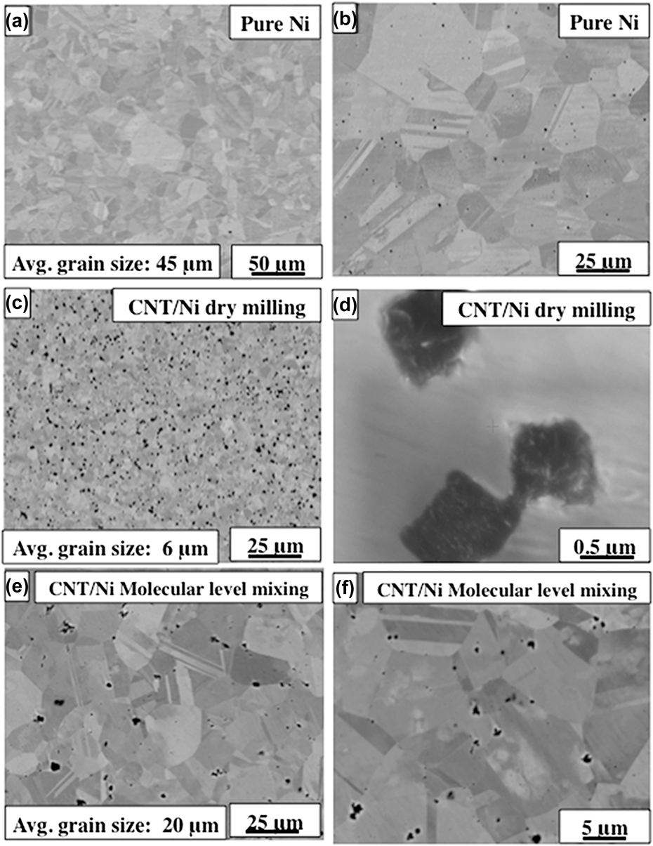
Back-scattered SEM images of the SPS processed pure nickel and CNT/Ni nanocomposites (DM and MLM) are shown in Fig. 1. Pure nickel [Figs. 1(a) and 1(b)] exhibits a uniform grain structure without any porosity with an average grain size of about 45 μm. The full and rapid densification of powder compacts without any substantial grain growth is one of the major advantages of SPS processing that is a result of sintering by joule heating and the spark plasma generated by the pulsed high electric current passing through the compact. CNT/Ni (DM) nanocomposite shows a substantially refined grain structure [Fig. 1(c)], as compared with the pure Ni, even though both samples were prepared with the same initial size of Ni powder. Within the Ni matrix, there appears to be a uniformly distributed second phase or possibly porosity, as shown in Fig. 1(c). However, a higher magnification SEM image, shown in Fig. 1(d), confirms that the regions exhibiting a darker contrast are actually CNT bundles of 1–2 μm in size, rather than porosity. Therefore, based on the comparison of microstructures of the SPS processed pure Ni and CNT/Ni composite (DM), it is apparent that addition of CNTs into the nickel matrix helps in grain refinement by possibly inhibiting grain growth and providing nucleation site for new grains during recrystallization. Figures 1(e) and 1(f) show SEM images from the CNT/Ni (MLM) nanocomposites, which also exhibit a uniform grain structure. Previous investigations of such CNT/Ni nanocomposites processed via MLM and SPS have clearly shown that there is a uniform distribution of individual CNTs within the nickel matrix.Reference Hwang, Lim, Tiley, Banerjee and Hong25
Back scatter SEM images of (a) and (b) pure nickel, (c) and (d) CNT/Ni DM, (e) and (f) CNT/Ni MLM.

B. X-ray diffraction analysis
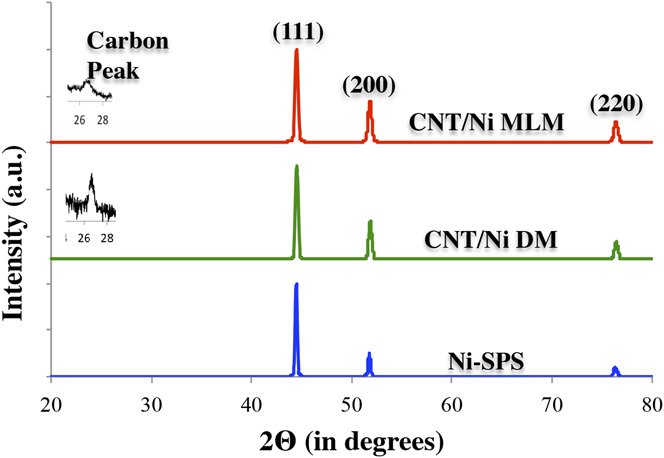
The XRD patterns for the SPS processed pure nickel and CNT/Ni nanocomposites are shown in Fig. 2. The XRD pattern for pure nickel shows peaks corresponding to the (111), (200), and (220) crystallographic planes of nickel. Both the dry-milled and molecular-level mixed CNT/Ni nanocomposites show an additional (0002) carbon peak. The presence of carbon peak in both the CNT/Ni nanocomposites confirms the presence of carbon nanotubes. In all three cases, the maximum intensity peak is the Ni(111) peak. The Ni(111)/Ni(200) intensity ratio for SPS processed pure Ni is 2.17, while that for dry-milled and SPS processed is 2.45, and finally for molecular-level mixed and SPS processed is 2.25. Comparing these three values with the standard ratio expected for randomly oriented Ni grains in the International Center for Diffraction Data (ICDD) files obtained from Joint Committee of Powder Diffraction Standards (JCPDS) of 2.38, it is apparent that there is no significant change in texture resulting from the introduction of CNT's in the nickel matrix. This is in contrast to previous publications on electro-deposited CNT/Ni nanocomposites where a clear increase in the Ni(200) peak intensity has been reported, indicating a change in texture due to the addition of CNTs.Reference Borkar and Harimkar33
XRD pattern obtained from pure nickel, CNT/Ni Dry milled, and CNT/Ni molecular-level mixed nanocomposites.

C. Micro Raman spectroscopy studies
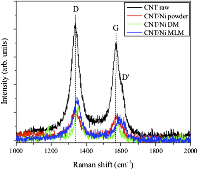
Raman spectroscopy was conducted to determine if any structural changes in the CNT occurred due to mechanical ball milling as well as during SPS due to heat, pressure, and current. Figure 3 shows Raman spectra for raw CNT, CNT/Ni ball milled powder, and SPS CNT/Ni (MLM) and CNT/Ni (DM) nanocomposites. The raw CNT serves as a reference with primary peaks at ∼1340, ∼1572 and a small shoulder peak at ∼1611 cm−1 wave numbers, corresponding to the D, G, and D′ peaks of the CNT, respectively.Reference Behler, Osswald, Ye, Dimovski and Gogotsi34,Reference Hwang, Neira, Scharf, Tiley and Banerjee35 The D peak origin is due to the breathing modes of sp 2 bonded atoms in rings, the G peak is attributed to the in-plane bond stretching of all pairs of sp 2 bonded atoms in both rings and chains, and the D′ peak is double-resonance Raman band induced by defects.Reference Behler, Osswald, Ye, Dimovski and Gogotsi34–Reference Ferrari36 The disorder in CNT, in a qualitative sense, can be monitored via the D and D′ peaks, their intensities, and the intensity ratio of the D to G peak (I D/I G). These parameters are considered defect dependent, e.g., bond length and angle (curvature) disorder at the atomic scale. In comparing the raw CNT to the CNT/Ni ball milled powder in Fig. 3, the D and G peak positions and I D/I G ratio do not change, suggesting that structural integrity of the CNT is preserved after mechanical ball milling, i.e., no increase in CNT structural disorder. In contrast, Raman spectra for SPS nanocomposites exhibit some minor peaks changes: (i) D peak increases from 1340 to 1357 (CNT/Ni DM) and 1348 (CNT/Ni MLM) cm−1, (ii) G peak increases from 1572 to 1582 (CNT/Ni DM) and 1591 (CNT/Ni MLM) cm−1, and (iii) I D/I G ratio increases from 1.2 to 1.9 (CNT/Ni DM) and 1.7 (CNT/Ni MLM). I D/I G ratios >2 indicate a highly disordered form of carbon.Reference Tuinstra and Koenig37 While these trends in the Raman peak shifts and intensity ratios may imply a slight increase in structural disorder due to SPS, they are more indicative of residual compressive stress occurring during SPS, which has been observed for other SPS CNT composites.Reference Inam, Yan, Reece and Peijs38,Reference Bakshi, Musaramthota, Virzi, Keshri, Lahiri, Singh and Agarwal39 The Ni grains will effectively compress the CNT under the SPS pressure causing the D and G peaks to shift slightly to higher wave numbers. Therefore, the structural stability of the CNT is relatively well maintained and the TEM studies presented below corroborate this.
Raman spectra showing the D, G, and D′ peaks from raw CNT, CNT/Ni ball milled powder, CNT/Ni Dry milled, and CNT/Ni molecular level mixed nanocomposites.

D. Microhardness and tensile behavior of CNT/Ni composites
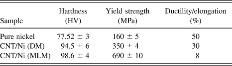
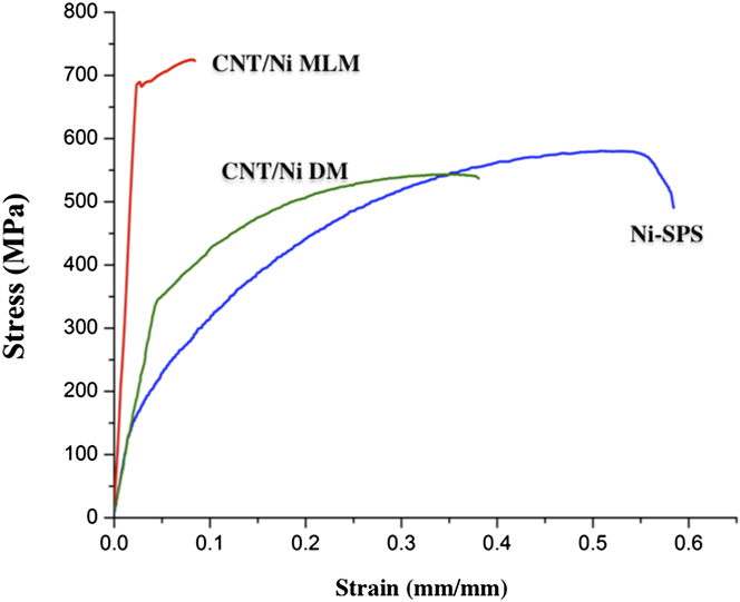
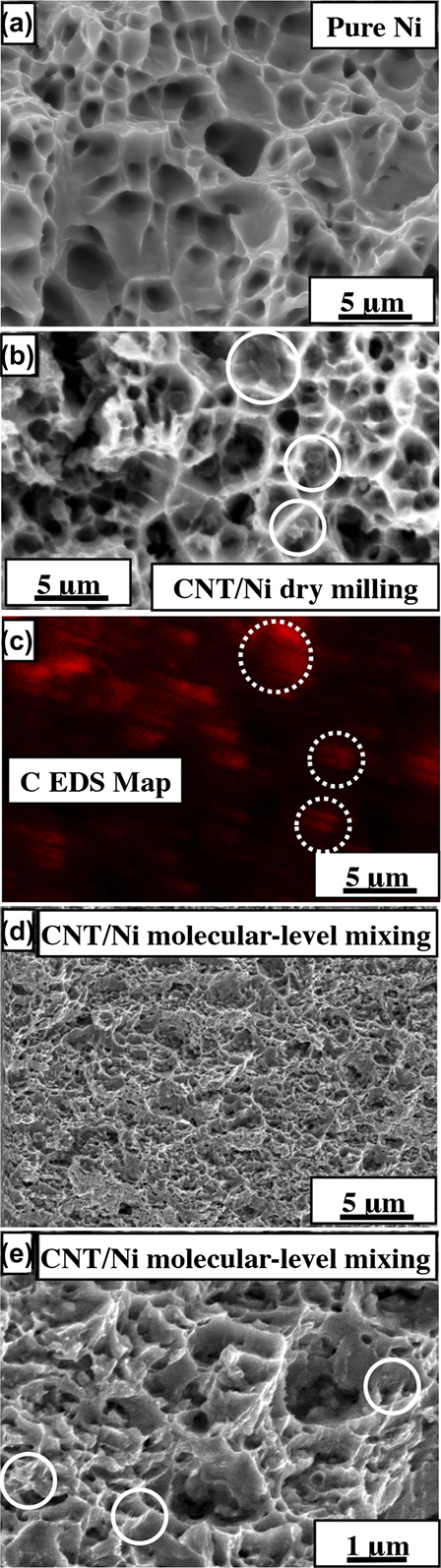
The Vickers microhardness of the CNT/Ni nanocomposites are shown in Table I. There is a considerable enhancement in the microhardness with the addition of CNTs to the nickel matrix. The hardness of CNT/Ni (MLM) nanocomposites is 98.6 HV and that of the CNT/Ni (DM) nanocomposite is 94.5 HV; both of these values are about 1.5 times higher than that of pure SPS processed nickel. The yield strength and elongation (tensile) properties of SPS processed pure nickel and both types of CNT/Ni nanocomposites are also listed in Table I. The corresponding engineering stress–strain curves for these materials are shown in Fig. 4. The tensile yield strength of CNT/Ni (DM) nanocomposite is 350 MPa, which is about 2 times higher than that of pure nickel (160 MPa). Even more striking is that the tensile yield strength of the CNT/Ni (MLM) nanocomposite is 690 MPa, about 4 times that of pure Ni and 2 times that of CNT/Ni (DM) nanocomposite. However, comparing the ductility of all three types of nanocomposites, while pure Ni exhibits about 50% elongation to failure, the elongation values for the CNT/Ni (DM) and CNT/Ni (MLM) are 30% and 8%, respectively. Comparing the stress–strain behavior (Fig. 4), it appears that while the CNT/Ni (DM) nanocomposite exhibits a modulus similar to that of SPS processed pure Ni, the CNT/Ni (MLM) nanocomposite exhibits a substantial higher modulus. Since the details of the deformation behavior of the CNT/Ni MLM nanocomposite have been discussed in a recent paper,Reference Cha, Kim, Arshad, Mo and Hong24 these are not mentioned here. However, it is important to note the contrasting aspects of deformation between the two types of CNT/Ni nanocomposites being compared in the present study. While the CNT/Ni (DM) nanocomposite exhibits a classical strain-hardening behavior all the way from yield to failure, similar to pure Ni, the CNT/Ni (MLM) nanocomposite exhibits the sharper yield point accompanied by a drop in stress and subsequently strain-hardening to a limited degree before failure. Figures 5(a), 5(b), and 5(d) are secondary electron SEM micrographs showing the fracture surfaces of the pure Ni, CNT/Ni (dry-milled), and CNT/Ni (molecular level mixed), respectively. From these images, it is evident that while pure Ni and CNT/Ni (DM) exhibit similar fracture surfaces, the CNT/Ni (MLM) nanocomposite exhibits a somewhat different fracture surface. The CNT/Ni (DM) nanocomposite fracture surface [Fig. 5(b)] exhibits typical cup and cone type failure characteristics, showing dimples of the order of few micrometers in size. This is indicative of a very ductile deformation behavior in agreement with the >30% elongation observed for this nanocomposite. An EDS carbon map, corresponding to the fracture surface shown in Fig. 5(b), is shown in Fig. 5(c). Based on this map, the location of the CNT bundles on the fracture surface can be determined and a few examples of these bundles have been marked with dotted circles in both Figs. 5(b) and 5(c). Contrastingly, the CNT/Ni (MLM) nanocomposite fracture surface [Fig. 5(d)], exhibits much smaller dimples of the order of sub-micron to at most a micron. Additionally, regions containing CNTs have been marked with circles in the higher magnification image of the fracture surface shown in Fig. 5(e). This is indicative of some strain localization and eventual failure at a lower level of strain. This is agreement with the observed lower ductility of the CNT/Ni (MLM) nanocomposite as compared to the CNT/Ni (DM) nanocomposite. However, from the perspective of strength, the CNT/Ni (MLM) exhibits a yield strength that is almost twice that of the CNT/Ni (DM) nanocomposite. The enormous strengthening in case of CNT/Ni (MLM) nanocomposites arises mainly due to the homogeneous distribution of individual CNTs within the nickel matrix.Reference Cha, Kim, Arshad, Mo and Hong24 The strong interfacial bonding between the CNTs and the Ni matrix is effective to improve the mechanical properties of CNT/metal nanocomposites. Despite the fact that the CNTs are in the form of sub-micron bundles in case of the CNT/Ni (DM) nanocomposite, a significant improvement in yield strength is observed and can be attributed in part due to grain size refinement. The experimental observations indicate that the uniform dispersion of CNT bundles is helping in grain refinement as well as possibly in load transfer between the metal matrix and the nanotube bundles. Therefore, comparing and contrasting the mechanical properties of these nanocomposites, it is evident that while the CNT/Ni (MLM) composite exhibits the highest tensile yield strength, the CNT/Ni (DM) composite exhibits a higher tensile ductility. The role of any residual stresses resulting from the SPS process should also be considered; especially since the graphite punches being in contact with the sintered material during the cooling step can result in considerably high cooling rates experienced by the sintered material. Such cooling during SPS ensures that heat does not unnecessarily stay retained in the sintered sample. However, when the sintering temperature is significantly low (800 °C) compared to the melting point of Ni (1455 °C), or T sintering = 0.62 T melting, the considerably high cooling rate is still unlikely to cause any significant residual stresses in the sintered composite.
Microhardness, yield strength, and elongation properties of pure nickel and CNT/Ni nanocomposites.

Stress–strain curves of CNT/Ni (DM and MLM) composites and pure Ni obtained from tensile test.

SEM micrograph showing the fracture surfaces of the (a) pure Ni, (b) CNT/Ni DM, and (d) CNT/Ni MLM composites after tensile test. (c) EDS C map corresponding to the fracture surface of CNT/Ni DM composite. (e) SEM micrograph showing the presence of CNTs in the fracture surfaces of the CNT/Ni MLM composite.

Additionally, it is worthwhile to compare the deformation behavior of CNT/Ni MLM processed nanocomposites with ultra-fine grained (UFG) nickel samples. Very high tensile yield strengths of about 990 MPa have been reported in the literature for UFG nickel samples, processed via equal channel angular pressing plus cold-rolling.Reference Krasilnikov, Lojkowski, Pakiela and Valiev40 These samples had grain sizes of about 0.33 μm and exhibited an elongation to failure of about 7%. SEM images of the fracture surface of these UFG nickel samples appear to exhibit a typical ductile failure with relatively large dimple sizes (larger than the grain size).Reference Krasilnikov, Lojkowski, Pakiela and Valiev40 Comparing the reported images of the fracture surface in case of UFG nickel with the fracture surface for the CNT/Ni MLM nanocomposite in the present study [Fig. 4(d)], the dimple sizes appear quite similar and in both cases exhibit extended edges. However, the grain size in case of the CNT/Ni MLM nanocomposite is substantially larger, about 15–25 μm, almost two orders of magnitude larger than that of the UFG nickel sample. Consequently, it can be concluded that the homogeneous distribution of CNTs in case of the MLM nanocomposite is primarily responsible for its very high yield strength (about 690 MPa).
E. TEM analysis
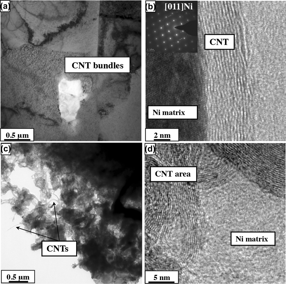
Figure 6(a) shows a bright-field TEM image of the CNT/Ni (DM) nanocomposite showing a CNT bundle embedded in the Ni matrix, which is consistent with the results obtained from SEM observations. A high-resolution TEM image from the same nanocomposite is shown in Fig. 6(b). This high-resolution image shows a sharp interface between a nanotube and the nickel matrix with no significant evidence of interfacial mixing across the two phases. A selected area diffraction (SAD) pattern of the [011] zone axis of pure nickel is included as an inset in Fig. 6(b). A low magnification bright-field TEM image of the CNT/Ni (MLM) nanocomposite is shown in Fig. 6(c). This image clearly shows that the CNTs are homogeneously distributed within the nickel matrix. Figure 6(d) shows a high-resolution TEM image of an individual CNT embedded in the nickel matrix. In this case too, the CNT/Ni interface is very sharp without any evident intermixing between the nanotube and the nickel. Unlike, CNT/Ni (ball milled) nanocomposites, in the molecular-level mixed nanocomposite, individual CNTs are homogeneously dispersed within the nickel matrix, thus providing a large number of very strong nickel-CNT interfaces that leads to improvement in mechanical properties such as high yield strength and microhardness. The distribution of individual CNTs was found to be more homogeneous in case of the CNT/Ni (MLM) nanocomposite as compared to the CNT/Ni (DM) nanocomposite that largely exhibited a distribution of small bundles of CNTs. Nevertheless, these CNT bundles in case of the CNT/Ni (DM) nanocomposite resulted in a high degree of grain refinement in the nickel matrix. While the CNT/Ni (MLM) nanocomposite exhibits the best nanotube distribution as well as the highest strength level, the processing of the CNT/Ni molecular-level powders is a relatively slow process, and the scalability of such a process can be challenging. In contrast, while the CNT/Ni (DM) nanocomposite does not exhibit the ideally desired distribution of nanotubes and consequently exhibits a lower strength level, the processing steps involved are relatively simple and in principle can be scaled up.
(a) Bright-field TEM image showing CNT bundle in Ni matrix of the CNT/Ni (DM) nanocomposite and (b) HRTEM image on the CNT/NI interface along with SAD pattern of pure Ni in inset of CNT/NI DM composite (c) bright-field TEM images of highlighted CNT region and (d) embedded CNTs in the Ni matrix of CNT/NI MLM composite.

IV. SUMMARY AND CONCLUSIONS
(1) Two types of CNT/Ni nanocomposites have been prepared using the SPS process, one using ball milled nickel and CNT precursors, referred to as CNT/Ni (DM) and the second one using molecular-level mixed CNT/Ni composite powders as a precursor, referred to as CNT/Ni (MLM).
(2) While both types of nanocomposites exhibited a substantial enhancement in microhardness and tensile yield strength as compared to SPS processed pure Ni, the CNT/Ni (DM) nanocomposite exhibited much higher ductility while the CNT/Ni (MLM) nanocomposite exhibited much higher tensile yield strength.
(3) The improvement in mechanical properties of the CNT/Ni (DM) nanocomposite results from a combination of composite strengthening due to the nanotubes, coupled with grain refinement of the nickel matrix, both effects resulting from the homogeneous distribution of small bundles of CNTs.
(4) The microhardness and yield strength of CNT/Ni (MLM) nanocomposite was significantly higher as compared to both CNT/Ni (ball milled) and pure nickel.
(5) The high strength of CNT/Ni (MLM) nanocomposite is mainly achieved due to the homogeneous distribution of individual CNTs in the nickel matrix and high interfacial strength due to a well-bonded Ni/CNT interface, permitting excellent load transfer between the matrix and the nanotubes.
ACKNOWLEDGMENTS
This work was financially supported by a grant (code No. FA2386-11-1-4008) from AOARD and partially supported by U.S. Air Force Research Laboratory (AFRL ISES Contract No. FA8650-08-C-5226) and a grant (code No. 2010K000275) from “Center for Nanostructured Materials Technology” under “21st Century Frontier R&D Programs” of the Ministry of Education, Science and Technology in Korea. The authors also gratefully acknowledge the Center for Advanced Research and Technology (CART) at the University of North Texas. The Korea Institute of Science and Technology (KIST) Institutional Program in the Republic of Korea has also provided partial support for this work.