
I. INTRODUCTION
Construction of ultra super critical boilers (USCB) requires materials with higher creep strength at lower possible cost, which has led to the development of low alloy heat-resistant ferritic steels. The new grade steel T23 (7CrWVMoNb9-6) has been developed on the basis of conventional 2.25Cr–1Mo steel (T22) by strengthening the material through alloying with vanadium and niobium act as precipitation hardening elements as well as with tungsten to enhance solid solution hardening. Reference Masuyama, Yokoyama, Sawaragi and Iseda1,Reference Miyata and Sawaragi2 As a result, the allowable stress of T23 steel at 853 K is approximately 1.8 times higher than that of T22 steel. Reference Arndt, Haarmann, Kottmann, Vaillant, Bendick, Kubla, Arbab and Deshayes3 Simultaneously, carbon contents in T23 steel is reduced to below 0.10 wt%, which provides a good weldability. It allows the welding of thin-walled tubes with δ < 10 mm without preheating and post-weld heat treatment (PWHT). Reference Bendick, Gabrel, Hahn and Vandenberghe4 Membrane waterwalls (MWW) are very large components working at lower temperatures zone of boiler and the final welding is performed on site where the PWHT is difficult to carry out. Furthermore, PWHT is expensive, time consuming, and may cause deformation of the final components. Therefore, the new grade T23 is considered as the most promising material for producing the MWW and has been widely used in USC power plants.
However, intergranular cracking has occurred in the weld metal zone of the welded joints of T23 steel used for MWW during actual service in several power plants of China since 2008, and the cause is still not clear yet. Reference Ji, Duan, Li, Zhang and Gu5,Reference Wang, Li, Yang, Ge, Yang and Ren6 Numerous leakages due to cracks were also detected in welds of MWW used another new grade low alloy resistant steel T24 (7CrMoVTiB10-10) with high creep resistance and low carbon content like T23 steel in Europe. Reference Nowack, Götte and Heckmann7 Zeman et al. Reference Zeman, Łomozik and Brózda8 have reported that low plastic properties, high mechanical properties, and high brittleness of the T24 steel joints in the case of omitting PWHT leads to cracking under additional static and dynamic stress during storage, transport, and water pressure test. The main purpose of this study is to investigate the mechanical properties of steel T23 welds including its creep rupture characteristics in the case of welding without PWHT. The results can provide us the information on understanding the reasons for the failure of T23 welds during service.
II. EXPERIMENTAL
T23 tubes with an outer diameter of 38.1 mm and wall thickness of 6.5 mm, in normalized and tempered condition were used as base metal for the preparation of butt welds. The matching GTAW-filler metal used Thyssen WZCr2WV wire of 2.4 mm in diameter. The chemical compositions of base metal (BM) and weld metal are listed in Table I.
Chemical compositions of the experimental materials (wt%).

The test joints were welded in the fixed vertical position (2G). The circumferential weld was carried out in 3 layers using manual GTAW process with the heat input of 12–15 kJ/cm, no preheating and with interpass temperature ≤250 °C. The welded joints were cooled slowly in ceramic wool to avoid hydrogen-induced cold cracking. Magnetic particle inspection and x-ray inspection of the welded joint revealed no welding defects.
A small segment cut from the welded test joint was used to perform metallographic examination in the as-welded condition. Optical microscopy was carried out to reveal the microstructures in different zones of the joint. Scanning electron microscopy (SEM) was carried out using QUANTA400 (FEI Company, Hillsboro, Oregon) for the observation of precipitates. Thin foil samples for transmission electron microscopy (TEM) were prepared to investigate the substructure of the weld metal (WM). Thin foils were examined in JEOL-2010 (JEOL Ltd., Tokyo, Japan) operating at 200 kV. The precipitates were also identified using carbon extraction replica by TEM with EDX.
Tensile tests at room and elevated temperatures, as well as bend tests were performed on the welds. The bend tests were completed by using a 26 mm plunger (d = 4t) to reach the 180° bend angle. Impact tests at room temperature have been performed on Charpy V specimens with cross section of 5 × 8 mm and notches machined in the central part of the weld and in the HAZ (≈1 mm from the fusion line). Micro-hardness profile across the welded joint was taken using a Vickers micro-hardness tester with a load of 9.8 N.
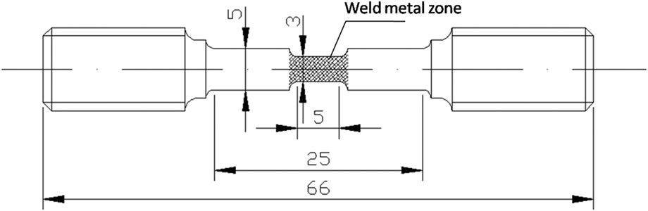
Smooth creep specimens with 5 mm in diameter and 25 mm in gauge length were sampled in the direction perpendicular to the weld line, ensuring that the weld metal was located in the center of specimen gauge length. To investigate the creep rupture characteristic of the WM, reduced section specimens with a 3 mm in diameter and 5 mm in gauge length in WM zone of joints were also prepared, as shown in Fig. 1. Creep rupture tests were conducted at 823 K with applied stresses in the ranges of 170–240 MPa.
Schematic of specimen used for creep testing of WM.

III. RESULTS AND DISCUSSION
A. Microstructure of welded joint without PWHT
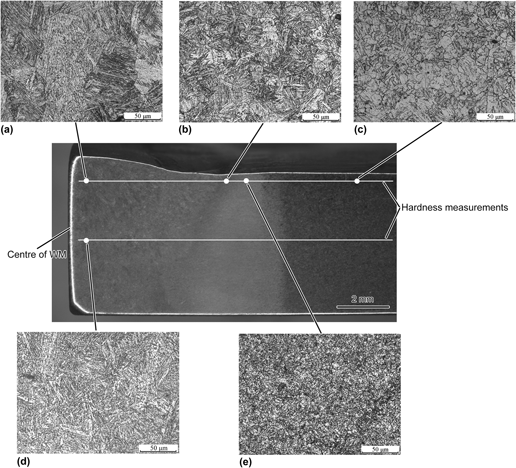
The optical micrographs in the different regions of the steel T23 welded joint are shown in Fig. 2. It is found that the cap weld exhibits a mixture of un-tempered martensite and bainite with a coarse prior austenite grain size [Fig. 2(a)], while the intermediate weld bead appears to be slightly tempered martensite/bainite due to the short-time tempering by cap weld runs [Fig. 2(d)]. In the coarse grained HAZ (CGHAZ), similar martensitic–bainitic microstructure is observed but with the decreased prior austenite grain size [Fig. 2(b)]. Fine grained HAZ (FGHAZ) has the finer prior austenite grain and its microstructure cannot be fully resolved using optical microscopy [Fig. 2(e)]. Reich et al. Reference Reich, Kessler, Bader and Oehmigen9 have reported the microstructure of the steel T24 after the HAZ cycle show a martensitic–bainitic microstructure and that a martensite portion of 70% for WM was formed at the fastest possible cooling rate in the quenching. This indicates T23 and T24 steels exhibit the similar characteristic of martensite transformation in the cooling process of welding. BM has fully tempered bainite microstructure, as shown in Fig. 2(c).
A macro section and microstructures of T23 steel welded joint without PWHT: (a) Cap weld, (b) CGHAZ, (c) BM, (d) intermediate weld bead and (e) FGHAZ.

Figure 3 shows the SEM images of the WM and BM. The features of lath martensite can be clearly recognized in the WM, as shown in Fig. 3(a). In addition, small M-A constituents lined up densely along subgrain boundaries with a bright contrast (highlighted with arrows) are resolved in Fig. 3(a), but there is no visible precipitates formed on grain boundaries. Compared with WM, BM reveals fully tempered bainite decorated with carbides precipitated on grain boundaries, which are identified as type M23C6 carbides in Ref. Reference Komai, Masuyama and Igarashi10.
SEM images of T23 steel welded joint without PWHT: (a) WM and (b) BM.

Figure 4 shows the thin foil TEM images of WM. TEM inspection further reveals that WM has a high proportion of un-tempered martensite with lath substructure and high density of dislocations. Small amount of fine MC carbides were found in lath interiors, as shown in Fig. 4(a), probably as a result of the self-tempering due to relatively slow cooling or short-time tempering of the following welding layer. Also it should be noted that there is no precipitate formed at grain boundaries, as shown in Fig. 4(b), which is consistent with the SEM results [Fig. 3(a)].
TEM thin foil micrographs of T23 WM: (a) laths and (b) grain boundaries.

Figure 5 shows the TEM micrographs of carbon extraction replicas, which clearly indicate that only a small number of fine carbides are formed in lath interiors and no precipitates are formed on grain boundaries.
Carbon extraction replicas of the T23 WM: (a) area 1 and (b) area 2.

The current investigations show that the microstructure of the WM without PWHT is characterized by a great portion of un-tempered martensite with small number of carbides precipitated in lath interiors.
B. Mechanical properties of welded joint without PWHT
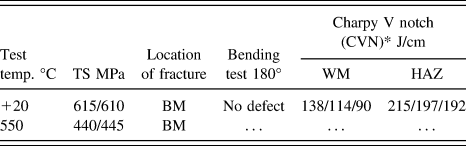
Table II lists the mechanical properties of the welded joints. The cross-weld tensile tested specimens ruptured in the BM at a tensile strength of 610–615 MPa at room temperature, which is higher than the minimum specified value 510 MPa for the T23 steel. At a bending angle of 180°, the face bend and root bend specimens did not produce any defects, indicating good plastic properties of the welded joint. The average CVN value of the WM is about half of HAZ due to its coarser grain size, but it is still higher than 100 J/cm. Reference Miyata and Sawaragi2 The results mentioned above reveal that the welded joint without PWHT exhibits high tensile strength, acceptable ductility, and toughness. Dhooge and Vekeman Reference Dhooge and Vekeman11 have found that the WM without preheating and PWHT has low impact toughness below 27 J (standard Charpy samples) by using the GTAW process with a high heat input up to 35 kJ/cm and thus recommended the upper limit of 25 kJ/cm in heat input. Our experimental results demonstrate their suggestions. Zeman et al. Reference Zeman, Łomozik and Brózda8 reported that the appearance of brittle cracks as a result of very low toughness of the HAZ and the WM of T24 steel submerged arc welds, and indicated weld cracking can be avoided by using welding speeds of 0.6–0.7 m/min, with linear welding energy of 8.6–10.0 kJ/cm. Thus, the required mechanical properties of welded joint at room temperature can be fulfilled by using the proper heat input in the case of omitting PWHT, and SAW processing should use lower heat input. The previous studies indicate some of the conditions under which acceptable mechanical properties may be achieved without PWHT.
Mechanical properties of steel T23 welded joint without PWHT.
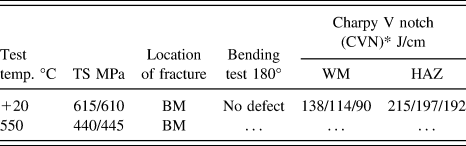
Notes: CVN*-value of breaking energy has been converted to breaking energy value for standard sample with cross section 8 × 10 mm.
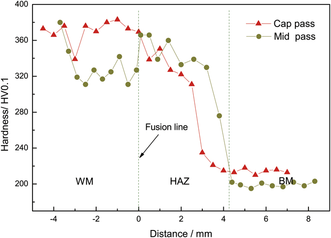
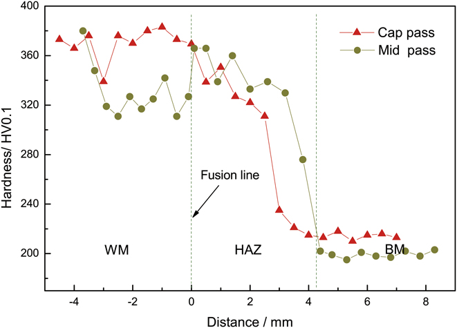
Figure 6 shows the hardness distribution, along an axis normal to the fusion line from the WM to BM of the welded joint, as shown in Fig. 2. The maximum hardness value of about 380 HV in the WM near the cap is higher than the maximum permitted hardness of 350 HV, whereas the maximum hardness in the HAZ does not exceed 350 HV. The average hardness of BM is about 200 HV. Zeman et al. Reference Zeman, Łomozik and Brózda8 also reported that the maximum hardness of 409 HV in the WM of steel T24 welded joint without PWHT in the case of preheating or regardless of preheating. The higher hardness in the WM was corresponding to a considerable portion of un-tempered martensite formed in this zone. It should be noted that the average hardness of the intermediate WM pass is lower by 30–60 HV than that of the cap weld pass, due to the tempering subsequently, showing that increasing layers and therefore obtaining thin weld pass can improve the properties of the WM. The Vallorec publication 12 emphasized that the cap weld pass should be as thin as possible so as to temper the weld beads below.
Hardness profile of T23 welded joints without PWHT.
C. Fractography of impact tests specimen for WM without PWHT
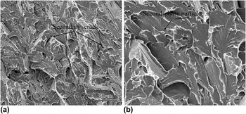
Typical fracture surface after Charpy impact test of the WM without PWHT is shown in Fig. 7. It exhibits brittle intra-crystalline fracture with dominantly quasicleavage feature. However, there are many fine tearing ridges created by dimple tearing between facets and secondary cracks formed. This presents the typical fracture mode of un-tempered martensite under impact load, which illustrates the transition of ductile fracture to brittle fracture. This fractographic results are well consistent with the moderate Charpy impact toughness of the WM listed in Table II. From Fig. 7(b), only very few visible second-phase particles were found on the cleavage facets, revealing very low carbides density in as-welded condition of WM.
Fracture surface of the WM impact specimen: (a) low magnification and (b) high magnification.

D. Creep rupture characteristics of welded joint without PWHT
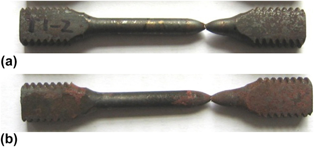
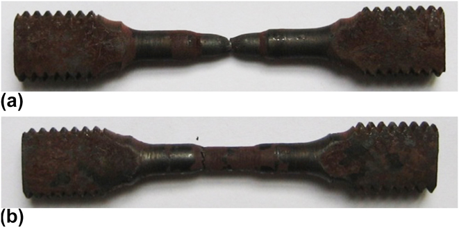
Figure 8 shows the appearances of smooth creep specimens of welded joints ruptured at stresses of 240 and 170 MPa. The fracture location occurring in the BW indicates that the WM exhibits the higher creep rupture strength than that of the BM. The extensive deformation and necking show that the BM has good ductility.
Fractured appearances of smooth creep specimens of welded joint: (a) 823 K, 240 MPa, fractured in BM; (b) 823 K, 170 MPa, fractured in BM.
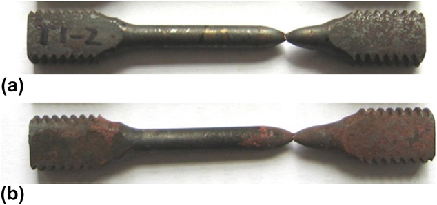
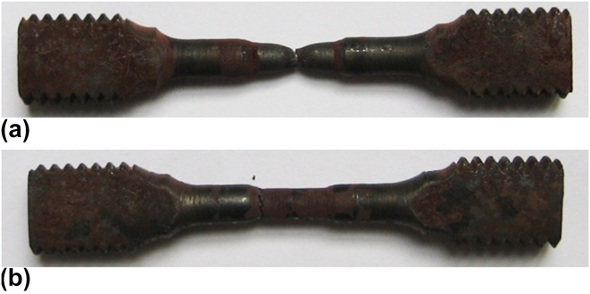
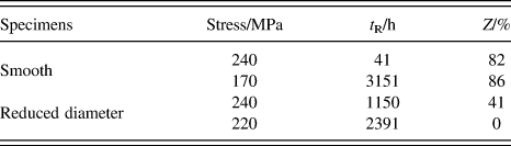
Figure 9 shows the appearances of the reduced diameter creep specimens in the WM zone of welded joints ruptured at stresses of 220 and 240 MPa. The creep-rupture properties of all specimens were summarized in Table III. At a stress of 240 MPa, the rupture life of the WM is considerably longer than that of the BM; however, the percentage reduction of area (PRA) of the WM is obviously lower than that of the BM. With the applied stress decreased to 220 MPa, the PRA of the WM drops rapidly and nearly to zero, indicating that the WM becomes more brittle during creep.
Fractured appearances of reduced diameter creep specimens in WM of welded joint: (a) 823 K, 240 MPa, fractured in WM; (b) 823 K, 220 MPa, fractured in WM.
Creep-rupture properties of steel T23 welded joint without PWHT.

Figure 10 exhibits the representative fractographs of the ruptured BM and WM of the welded joint. The fracture mode of the BM is typical of ductile transgranular fracture with dimples as shown in Fig. 10(a), which corresponds to the higher PRA. The fracture surface of the WM seen in Fig. 10(b) is obviously different from that of the BM. A prominent intergranular fracture behavior with the absence of dimple pattern is observed in the WM, demonstrating the brittle failure mode and corresponding to the very low rupture ductility.
Fracture surfaces of the creep specimen ruptured at (a) BM (170 MPa/3151 h) and (b) WM (220 MPa/2391 h).

Figure 11 shows the profile and optical microstructures of the reduced diameter creep specimens in the WM zone of welded joints ruptured at stresses of 220 MPa. From Fig. 11(a), it is clearly observed that the failure location is at the WM. The microstructure adjacent to the fracture location is shown in Fig. 11(b). It can be seen that the remnant martensitic lath is still clearly visible, revealing that the recovery and recrystallization kinetics of the un-tempered martensite in the as-welded WM is slow during creep test at 823 K. It should be noted that a small number of creep voids were discovered in the grain boundaries (highlighted with arrows). The average hardness of the WM (in mid thickness) after creep is about 323 HV, which has little change compared with as-welded condition.
Profile and optical microstructure of the fractured WM crept at 220 MPa for 2391 h: (a) profile and (b) microstructure.

Figure 12 shows the SEM micrographs of the fractured WM tested at 220 MPa for 2391 h, it was found that there are two modes leading to the finally fracture. One is the wedge mode taken place at the junction of three grain boundaries, as shown in Fig. 12(a). The other is the cavitation mode, showing that the creep voids coalesced and resulted in the micro-crack along the grain boundaries, as shown in Fig. 12(b). The cavitation mode appears to be the dominant mechanism for the fracture of the WM. It was also found that majority of the M-A constituent has been decomposed, whereas almost no carbide precipitated on the boundaries even after creep at 823 K for a comparative long time. This illustrates that the formation of the voids in the WM does not result from the contribution of carbides precipitated on the boundaries.
SEM images of the fractured WM crept at 220 MPa for 2391 h: (a) wedge cracking and (b) coalesced voids.

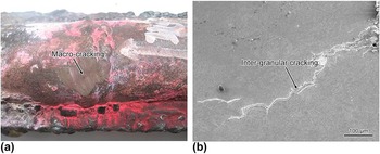
WM has the similar composition to the BM with the exception of the lower carbon content. The difference between them is the dissimilar initial microstructure as a result of experiencing different heat treatment. The BM is in a normalized and tempered condition; while the WM without PWHT exhibits similar microstructural characteristics as quenched T23 steel. The WM without PWHT exhibits the higher strength at both room and elevated temperature than the BM; however, it will become brittle during creep as a result of the as-welded microstructure containing a great amount of un-tempered martensite transformed in the fast cooling process of welding. Similar inter-granular cracking, as discussed in Fig. 12, occurred in the WM zone of service steel T23 welded joint at power plants, as shown in Fig. 13, confirming that the reason for the cracking (in service) is creep brittleness. Mohyla and Foldyna Reference Mohyla and Foldyna13 have reported that nontempered welded joints of steel T23 undergo a process of secondary hardening during long-term exposure at elevated temperatures, which is at the expense of ductility. According to our investigations, no obvious increase of hardness in the WM after creep at 550 °C for 2391 h, indicating that secondary hardening is not the main reason for its creep brittleness. Although no rise in hardness occurs during creep, WM still maintains much higher hardness than BM. As a result of its higher strength, the tensile stress in the welded joint cannot be relaxed by plastic deformation because of the insufficient ductility of the WM at high temperature, which consequently resulted in brittle intergranular cracks. Furthermore, discontinuities presented in the joints with high stress concentrations (welding residual stress as well as welding nonconformities and geometric discontinuities in the cross sections of joints with partial weld penetration) also facilitate the formation of brittle fractures. The effect of geometric stress concentrators has been discussed in the Vallourec publication. 12 If this is applicable in service, this may indicate the necessity for preheat and possibly PWHT. For background, Vallourec recommend weld procedure qualification by simulation of operating conditions.
Example of service failures of T23 steel welded joint in MWW: (a) profile of failure welded joint and (b) inter-granular cracking in the WM.

Based on the above mentioned discussions, eliminating un-tempered martensite and reducing hardness in the WM by PWHT is the most effective measure to avoid the appearance of brittle cracks during creep service. Dhooge and Vekeman Reference Dhooge and Vekeman11 considered that the need for a PWHT can be evaluated using the following criteria: (i) maximum hardness 350HV10 (power generation application); (ii) minimum impact toughness at room temperature: 27 J [pressure equipment direction]. Despite its impact toughness being higher than the required minimum value, the hardness of T23 WM without PWHT exceeds the maximum permitted value. Thus, PWHT is essential to reduce the hardness in T23 WM and to enhance its rupture ductility during creep. For high-strength martensitic steels like T91, the PWHT is mandatory, indicating that the untempered martensite with high hardness is detrimental to the creep properties.
In addition, lowering the cooling rate of welding with increasing preheating temperature or heat input suppresses martensite transformation and promotes the formation of bainitic structure with lower hardness and better toughness. However, it should be noted that excessively high preheating temperature and high heat input may render coarser microstructure in the WM and HAZ, which is harmful to the impact toughness. An alternative approach may be considered to replace the current T23 strength matching consumable with a lower strength consumable, e.g., consumable for welding T22 or T12 steel.
IV. CONCLUSION
Microstructural analysis and mechanical property testing of the T23 welded joints in as-welded condition using GTAW process with matching filler metal were performed to investigate the mechanisms of inter-granular cracks occurred in the WM during service. The results can be summarized as follows:
-
(1) Compared to HAZ, T23 WM shows a similar un-tempered martensitic/bainitic microstructure in as-welded condition but a coarser prior austenite grain size. The high proportion of un-tempered martensite in WM resulted in the hardness level exceeding the maximum permitted value of 350 HV. This was associated with the formation of inter-granular cracking at creep test stresses.
-
(2) Micro-alloying elements largely remained in the matrix of T23 WM without forming precipitate due to reasonably fast cooling after welding. However, few precipitates of their carbides as well as no rise of hardness in the WM after creep at 550 °C for 2391 h, indicated that secondary hardening is not the main reason for the creep brittleness.
-
(3) In the case of omitting PWHT, T23 welded joint of thin wall thickness with the proper heat input exhibits high tensile strength, good ductility, and sufficient impact toughness in the WM. But, PWHT is still essential to reducing the hardness and consequently enhancing the ruptured ductility during creep or service exposure.
ACKNOWLEDGMENTS
The authors would like to express their gratitude for projects supported by the National Natural Science Foundation of China (51374153 and 51574181) and Supported by State Key Lab of Advanced Welding and Joining, Harbin Institute of Technology (AWJ-Z15-02).