1 Introduction
The back and forth movement of insect wings produces complicated flow structures such as leading-edge vortex (LEV), root vortex (RV), tip vortex (TV) and shear layers. These structures form a doughnut-shaped vortex ring and induce a strong downwash at the core of the ring (e.g. Poelma, Dickson & Dickinson Reference Poelma, Dickson and Dickinson2006, Aono, Liang & Liu Reference Aono, Liang and Liu2008). Among those structures, the LEV has been regarded as an essential component, as it can augment the aerodynamic force of insect wings. Ellington et al. (Reference Ellington, Van den Berg, Willmott and Thomas1996) discovered a swirl-like LEV on a hawkmoth wing, and Dickinson, Lehmann & Sane (Reference Dickinson, Lehmann and Sane1999) observed a stable LEV on a robotic wing model of a fruit fly. Numerous follow-up studies of flapping-wing aerodynamics clearly demonstrated this mechanism (e.g. Sane & Dickinson Reference Sane and Dickinson2001, Ramamurti & Sandberg Reference Ramamurti and Sandberg2002, Sun & Tang Reference Sun and Tang2002), also revealing applicability to the design of flapping-wing micro air vehicles (FWMAVs) (e.g. Ellington Reference Ellington1999).
Since it was found that the ‘quasi-steady’ Coriolis and centripetal forces stabilize the LEV (Lentink & Dickinson Reference Lentink and Dickinson2009a
,Reference Lentink and Dickinson
b
), recent studies of flapping-wing aerodynamics have aimed to elucidate the fundamental relationship between the LEV and consequent aerodynamic characteristics. The aspect ratio, AR, and/or advance ratio,
 $J$
, which govern the Coriolis and centripetal accelerations, were utilized as major parameters in numerous earlier works (e.g. Wolfinger & Rockwell Reference Wolfinger and Rockwell2014, Han, Chang & Cho Reference Han, Chang and Cho2015a
, Kruyt et al.
Reference Kruyt, van Heijst, Altshuler and Lentink2015, Han, Chang & Han Reference Han, Chang and Han2016). These efforts clearly demonstrated that AR and
 $J$
are closely associated with the LEV. In particular, low-AR and low-
 $J$
conditions play a substantial role in stabilizing the LEV.
In contrast, relatively few studies have investigated the effects of a lateral inflow on flapping wings. Most studies instead aimed to clarify certain aspects of the flight dynamics, such as a trim search, system identification and stability and manoeuvrability as compared to the fundamental aerodynamic characteristics. Of note is that there were different views with regard to lateral flight stability. While Faruque & Humbert (Reference Faruque and Humbert2010a
,Reference Faruque and Humbert
b
) and Cheng & Deng (Reference Cheng and Deng2011) predicted that the first natural mode of lateral motion is a stable slow subsidence mode, Zhang & Sun (Reference Zhang and Sun2010a
) and Zhang, Wu & Sun (Reference Zhang, Wu and Sun2012) revealed that the first mode is unstable. Sun (Reference Sun2014) explained that a lateral wind commonly results in a serious imbalance between two LEVs on a pair of flapping wings, causing both a positive sign of the roll moment derivative and flight instability. This occurs because a lateral wind running from the wingroot to the wingtip intensifies both the LEV and the aerodynamic force, whereas the wind in the opposite direction deconcentrates the LEV. He also argued that these characteristics can only be found in high-fidelity simulations, such as his computational fluid dynamics approach, as other studies relying on simplified aerodynamic models (Sane & Dickinson Reference Sane and Dickinson2002; Han et al.
Reference Han, Chang, Kim and Han2015b
) are not able to take the effects of a spanwise flow into account. This implies that the lateral wind is the primary source directly interrupting the centripetal and Coriolis forces of the LEV, probably resulting in more dramatic consequences with regard to the aerodynamic and flight dynamic characteristics of flapping-wing systems than that of AR and
 $J$
. It should also be noted that the wing–wing interaction is not completely negligible during hovering (Han, Kim & Han Reference Han, Kim and Han2019). This indicates that wing–wing and/or wing–body interactions under a lateral wind would not be negligible either, as a lateral wind passes the other wing and body before reaching the wing of interest. These all clearly suggest that accurate aerodynamic characteristics pertaining to a lateral inflow should be provided in more detail. Unfortunately, however, such interactions have not been investigated thus far.
In this study, we measured the time-varying aerodynamic forces and moments on a hawkmoth-like flapping wing under a steady lateral inflow. A dynamically scaled-up robotic manipulator and a simultaneously driven towing carriage were employed to produce the inflow. The speed of lateral inflow, wing–wing interaction and wing–body interaction were also considered in this study. We found that wing–wing interaction was not completely negligible overall under a lateral inflow. It was also found that wing–wing interaction plays a considerable role in static stability.
Experimental set-up. (a) Dynamically scaled-up manipulator with kinematic definitions. (b) Servo-driven towing tank.

2 Experimental set-up and procedure
Figure 1(a) shows the dynamically scaled-up robotic manipulator and its kinematic definitions. This manipulator has been specified in several previous papers (e.g. Han et al.
Reference Han, Chang and Han2016). The hawkmoth Manduca sexta was selected as a reference insect; its morphological parameters have been thoroughly documented (e.g. Ellington Reference Ellington1984, Willmott & Ellington Reference Willmott and Ellington1997, Kim & Han Reference Kim and Han2014). The hawkmoth-like wing planform (Usherwood & Ellington Reference Usherwood and Ellington2002) had a spanwise length
 $b$
of 250 mm, and
 $R$
, denoting the length from the pivot to the wingtip, was 275 mm. The aspect ratio was 3.09, and the non-dimensional second moment wing area was 0.524 (refer to Han, Chang & Han (Reference Han, Chang and Han2017) for details). The body was made of polylactic acid filament with a 3-D printer. This shape was simplified from the reference model (Nguyen, Han & Han Reference Nguyen, Han and Han2017), and had a length of
 $0.81b$
(Ellington Reference Ellington1984). A body-fixed frame and a wing-fixed frame were employed to analyse the results (the superscripts
 $B$
and
 $W$
on each axis denote the frames). The relationship between the two frames is shown in (2.1) and (2.2) (refer to Han et al. (Reference Han, Chang and Han2017) for details). A six-axis force/torque sensor (Nano17-IP68, ATI Industrial Automation) was mounted between the output shaft of the manipulator and the base of the right wing (the red part in figure 1). This sensor was connected to a signal conditioner and a DAQ board (PCI-6143, National Instruments) installed in a PC. An in-house code written in LabVIEW™ was used to collect the aerodynamic force and moment. The aerodynamic moments were not only recalculated on an artificial centre of gravity (CG) of the hawkmoth, but were also transformed into a cross-point between the shoulder line and the
 $Z^{B}$
-axis with the distance
 $\boldsymbol{d}^{B}$
to provide the static margin and the proper CG location for potential FWMAVs (as discussed later). The resolutions were
 $1/320$
N and
 $1/64$
N mm in forces and moments, respectively.
 $$\begin{eqnarray}\displaystyle & \displaystyle \boldsymbol{F}^{B}=\unicode[STIX]{x1D64D}^{W\rightarrow B}\boldsymbol{F}^{W}, & \displaystyle\end{eqnarray}$$
 $$\begin{eqnarray}\displaystyle & \displaystyle \unicode[STIX]{x1D648}^{B}=\boldsymbol{R}^{W\rightarrow B}\boldsymbol{M}^{W}+\boldsymbol{d}^{B}\times \unicode[STIX]{x1D64D}^{W\rightarrow B}\boldsymbol{F}^{W}, & \displaystyle\end{eqnarray}$$
where
 $$\begin{eqnarray}\displaystyle & \displaystyle \unicode[STIX]{x1D64D}^{W\rightarrow B}=[\unicode[STIX]{x1D64D}^{B\rightarrow W}]^{\text{T}}=\left[\begin{array}{@{}ccc@{}}\cos \unicode[STIX]{x1D719}\cos \unicode[STIX]{x1D703} & -\!\sin \unicode[STIX]{x1D719} & \cos \unicode[STIX]{x1D719}\sin \unicode[STIX]{x1D703}\\ \sin \unicode[STIX]{x1D719}\cos \unicode[STIX]{x1D703} & \cos \unicode[STIX]{x1D719} & \sin \unicode[STIX]{x1D719}\sin \unicode[STIX]{x1D703}\\ -\!\sin \unicode[STIX]{x1D703} & 0 & \cos \unicode[STIX]{x1D703}\\ \end{array}\right], & \displaystyle\end{eqnarray}$$
 $$\begin{eqnarray}\displaystyle & \displaystyle \boldsymbol{d}^{B}=\left[\begin{array}{@{}ccc@{}}0 & 0.12b & 0\\ \end{array}\right]^{\text{T}}. & \displaystyle\end{eqnarray}$$
Figure 1(b) describes a servo-driven towing carriage on a water tank. A rack-and-pinion combination was installed on the carriage to move the manipulator along the longitudinal axis of the tank. The rack gear was 2.1 m long, and the pinion gear was simultaneously driven with the other motors of the manipulator by a synchronized command signal. All servo motors (XH430-W210-R, Robotics) were connected with a parallel circuit which operated at a baud rate of 2 Mbps. High-resolution encoders of
 $0.088^{\circ }$
equipped in each motor enabled precise positioning of this system. An in-house code written in LabVIEW™ generated discrete position data array and updated the angular position at intervals of every 5 ms. This updating rate,
 $1.6\times 10^{3}$
times higher than the wingbeat frequency, was enough to create smooth wingbeat motion under the lateral wind (refer to Han et al. (Reference Han, Chang and Han2016) for more details).
Variables for the wing–body and/or wing–wing interactions.

The aerodynamic forces and moments on the right wing were measured with respect to four different geometrical configurations to see the wing–wing and/or wing–body interactions as shown in figure 2. The sideward ratio
 $J_{lateral}$
, which is defined in (2.5), was also used to investigate the speed of lateral inflow. In order to determine the range of
 $J_{lateral}$
, we studied a biological observation on a hawkmoth in lateral manoeuvre (Greeter & Hedrick Reference Greeter and Hedrick2016). They showed that a hawkmoth can move sideways at up to
 ${\sim}80~\text{cm}~\text{s}^{-1}$
, which corresponds to
 $J_{lateral}$
of
 ${\sim}0.15$
. Accordingly, we separated
 $J_{lateral}$
into the seven values of
 $-0.18$
,
 $-0.12$
,
 $-0.16$
, 0 (hovering), 0.06, 0.12 and 0.18. As shown in figure 1,
 $J_{lateral}$
had a positive sign when the body moved from left to right. Given that the wingbeat motion of the left wing was identical to that of the right wing in a mirror reflected on the longitudinal plane (
 $X^{B}$
–
 $Z^{B}$
plane), the aerodynamic force and moment on the left wing were predictable. When the body moved to the right with
 $J_{lateral}=0.12$
, for example, the aerodynamic force and moment on the left wing could be determined as for the right wing with
 $J_{lateral}=-0.12$
. Here, the three components in the force and moment, i.e. the side force
 $F_{Y}^{B}$
, roll moment
 $M_{X}^{B}$
and yaw moment
 $M_{Z}^{B}$
, had to be reversed for their proper signs. The Reynolds number
 $Re$
, which is a function of
 $J_{lateral}$
, as shown in (2.6), had a range from
 $0.96\times 10^{4}$
to
 $1.54\times 10^{4}$
. This range is sufficiently beyond the critical
 $Re$
of
 ${\sim}10^{3}$
where the burst LEV appeared (Birch, Dickson & Dickinson Reference Birch, Dickson and Dickinson2004; Lu, Shen & Lai Reference Lu, Shen and Lai2006; Garmann, Visbal & Orkwis Reference Garmann, Visbal and Orkwis2013) and also lower than
 ${\sim}2.4\times 10^{4}$
, which is the maximum
 $Re$
maintaining the stable LEV (Kruyt et al.
Reference Kruyt, van Heijst, Altshuler and Lentink2015), implying negligible
 $Re$
dependency. This range of
 $Re$
is also directly applicable to the FWMAV design, which is expected as
 ${\sim}10^{4}$
(Ellington Reference Ellington1999).
 $$\begin{eqnarray}\displaystyle & \displaystyle J_{lateral}=\frac{U_{lateral}}{\bar{U}_{tip}}=\frac{U_{lateral}}{2\unicode[STIX]{x1D719}Rf}, & \displaystyle\end{eqnarray}$$
 $$\begin{eqnarray}\displaystyle & \displaystyle Re=\frac{(\bar{U}_{tip}+U_{lateral})\cdot \bar{c}}{\unicode[STIX]{x1D708}}=\frac{(1+J_{lateral})\bar{U}_{tip}\cdot \bar{c}}{\unicode[STIX]{x1D708}}. & \displaystyle\end{eqnarray}$$
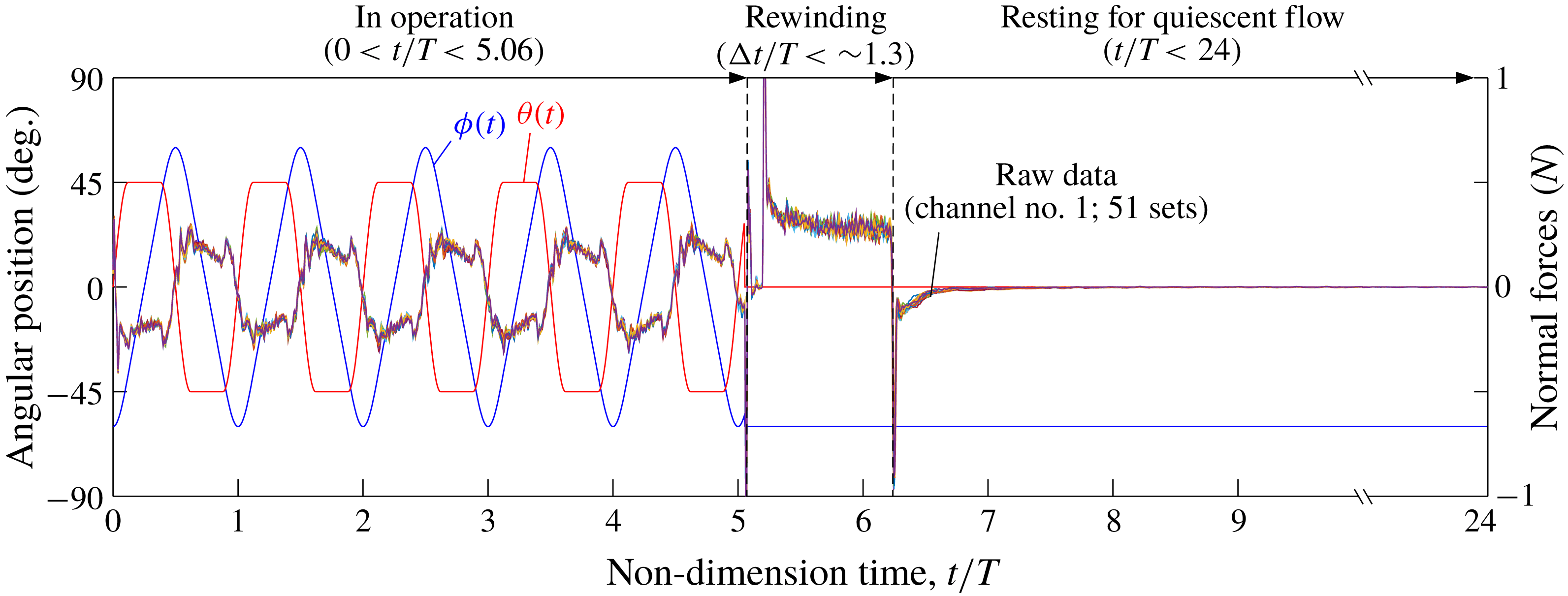
Figure 3 explains the entire measurement process when moving sideways. We employed the prescribed motion profiles based on previous works (Sun & Tang Reference Sun and Tang2002; Han et al.
Reference Han, Chang, Kim and Han2015b
). This piecewise profile had
 $\unicode[STIX]{x0394}t/T=0.24$
as a deceleration–acceleration period in the
 $\unicode[STIX]{x1D719}$
axis and a rotational phase of
 $\unicode[STIX]{x0394}t/T=0.24$
with symmetrical pitching-up wing rotation in the
 $\unicode[STIX]{x1D703}$
axis. This can also be expressed as
 $t/T_{R,\unicode[STIX]{x1D719}}=0.24$
and
 $t/T_{R,\unicode[STIX]{x1D703}}=0.24$
, as in the notation of Han et al. (Reference Han, Chang, Kim and Han2015b
). The process consisted of three sequences: operation, rewinding and resting. During the operation, the wing started near the sidewall of the towing tank and proceeded with wingbeat motion from
 $t/T=0.0$
to 5.06. The use of these five wingbeat cycles was intended both to avoid the inertial force due to a sudden departure in the initial stage and to build a fully developed wake (Birch & Dickinson Reference Birch and Dickinson2003; Han et al.
Reference Han, Kim and Han2019). The carriage then rewound the manipulator to the initial point at
 $t/T=5.2$
. This process took
 ${\sim}1.3T$
when the model had the maximum distance with
 $J_{lateral}=\pm 0.18$
. The other cycles from
 $t/T=\,\sim 6.5$
to 24 were used to recover the quiescent flow of the medium. Here, the raw data at the last single cycle (
 $23<t/T<24$
) were used to align the data to the tare weights. It was checked in advance that 2 min (the corresponding wingbeat cycle is
 $15T$
) was enough to restore the sensor output considering the resolution provided by the manufacturer. We iterated this entire measurement process 24 times to reduce unexpected noises coming from the environment. This number of cycles was also sufficient to converge an ensemble average (refer to Han et al. (Reference Han, Chang and Han2016) for details).
Measurement process consisting of the three sequences of operation, rewinding and resting.

The measurement uncertainty was calculated as follows. The precision errors along
 $\unicode[STIX]{x1D719}$
and
 $\unicode[STIX]{x1D703}$
were
 $\pm 0.073\,\%$
and
 $\pm 0.376\,\%$
(
 $120\pm 0.088^{\circ }$
and
 $90\pm 0.088\pm 0.25^{\circ }$
), respectively, where
 $\pm 0.25^{\circ }$
is the maximum tolerance of the bevel gearbox as guaranteed by the manufacturer. The 5 ms temporal resolution of the driving signals also had a precision error of
 $\pm 0.063\,\%$
. This was based on the digitized points of 1600 on both axes during a single wingbeat cycle. The water temperature was maintained at
 $16.2\pm 0.8\,^{\circ }\text{C}$
, resulting in a negligible density change within
 $\pm 0.008\,\%$
. Including the sensor resolution of
 $3.13\times 10^{-3}$
N and
 $15.6\times 10^{-3}~\text{N}~\text{mm}$
, the systematic uncertainty levels were determined to be
 $\pm 2.41\,\%$
(
 $\pm 0.005$
N) and
 $\pm 1.06\,\%$
(
 $\pm 0.534$
N mm); these percentages were based on the maximum levels of amplitudes in the case of
 $J_{lateral}=0$
(refer to Han et al.
Reference Han, Chang and Cho2015a
for details).
Two-dimensional digital particle image velocimetry (DPIV) was employed to diagnose the flow structures. Similar to the work of Han et al. (Reference Han, Chang and Han2016), we selected eight individual chordwise cross-sections ranging from
 $0.2b$
to
 $0.9b$
to predict the three-dimensional vortical structures. In addition, one spanwise cross-section parallel to the wing surface at the middle of the downstroke (
 $t/T=4.75$
) was selected to collect quantities along the spanwise axis. All image pairs were obtained by a commercial digital camera (Sony RX10-III) with a shutter speed of
 $1/250$
s. The resolution was
 $1920\times 1080$
pixels. Polymethylmethacrylate powder particles, which had a diameter of
 $100~\unicode[STIX]{x03BC}\text{m}$
, were used as the tracer particles. The camera was controlled by a simultaneous trigger pulse generated by a DAQ system. An open-source PIV code (Thielicke & Stamhuis Reference Thielicke and Stamhuis2014) was then employed to extract the vector fields. A
 $40\times 40$
-pixel interrogation area with 50 % overlap gave us the field with a
 $53\times 95$
resolution in the entire field of view (FOV). A total of 51 image pairs were used to obtain the phase-averaged velocity fields in each FOV, and these were reconstructed in three dimensions with the wing shape.
The DPIV uncertainty was calculated in the following manner with tables from Raffel et al. (Reference Raffel, Willert, Wereley and Kompenhans2007). We collected the mean particle image diameter, displacement and density per interrogation area using MATLAB® with a peak detection algorithm that finds the local maxima in selected images. For the chordwise cross-sections, the mean diameter, displacement and density were 3.52 pixels, 0–2.24 pixels and 0.0167 particles (
 $N=26.72$
in a window), respectively, which gave corresponding root-mean-square errors
 $\unicode[STIX]{x1D700}_{rms}$
of 0.02, 0.015 and 0.02 pixels. They also created bias errors
 $\unicode[STIX]{x1D700}_{bias}=-0.004$
and
 $-0.0275$
pixels. The valid detection probability was
 ${\sim}100\,\%$
due to the sufficient particle density, which exceeded
 $N>15$
. The errors overall were
 $-0.0315\pm 0.055$
; these correspond to
 $-1.41\pm 2.5\,\%$
of the maximum displacement. In the spanwise cross-sections, the wing with
 $J_{lateral}=0.18$
strikingly accelerated the particles near the wing surface close to the wingtip velocity due to a lateral inflow (as discussed later). The displacement had a range from 0 to 2.98 pixels, and the root-mean-square error was rarely changed. The overall relative error based on the maximum displacement became
 $-1.06\pm 1.9\,\%$
.
Note that flapping wings always induce significant flux in the radial direction (e.g. Garmann et al.
Reference Garmann, Visbal and Orkwis2013), causing in-plane and/or out-of-plane motions of the particles perpendicular to the FOV. The lateral movement with the
 $J_{lateral}$
in this study also probably accelerated the motion, degrading the peak detection performance in the PIV processing. In order to prevent such an effect of the out-of-plane motion, we employed a relatively thick laser sheet (
 ${>}3$
mm) and short intervals in each pair of images (
 $1/250~\text{s}$
). The laser thickness corresponds to
 ${\sim}30$
times the particle diameter and to more than 6 times the particle displacement moving with the maximum velocity; these were sufficient to prevent the degradation. The particle density of
 $N>26$
in this study, which was much higher than
 $N>4$
, also much helped to avoid this effect (Raffel et al.
Reference Raffel, Willert, Wereley and Kompenhans2007). Nonetheless, the quantities extracted from the DPIV results, such as sectional lift forces, would be somewhat distorted (as discussed later).
3 Results and discussion
3.1 Fundamental aerodynamic characteristics under a lateral inflow
Figure 4(a–c) shows the time-varying coefficients of the lift
 $C_{L}$
, side force
 $C_{F_{Y}}^{B}$
and roll moment
 $C_{M_{X}}^{B}$
on the aforementioned cross-point. The left wing and body were detached from the model as shown in figure 2(a), so that the results in figure 4 were isolated from the wing–wing or wing–body interactions. The coefficients were extracted from the fifth wingbeat cycles (
 $4.0<t/T<5.0$
), which were sufficiently far from the aforementioned contaminations. The coefficients were extracted using (3.1)–(3.3), where
 $\hat{r}_{2}$
denotes the non-dimensional second moment of the wing area pinpointing the reference point on the wing surface in hover (Ellington Reference Ellington1984; Lua, Lim & Yeo Reference Lua, Lim and Yeo2014; Han et al.
Reference Han, Chang and Han2017):
 $$\begin{eqnarray}\displaystyle & \displaystyle C_{L}=-C_{F_{Z}}^{B}=\frac{2(F_{X}^{W}\sin \unicode[STIX]{x1D703}-F_{Z}^{W}\cos \unicode[STIX]{x1D703})}{\unicode[STIX]{x1D70C}\bar{U}_{tip}^{2}\hat{r}_{2}^{2}\cdot S}=\frac{-2F_{Z}^{B}}{\unicode[STIX]{x1D70C}(2\unicode[STIX]{x1D719}_{amp}fR)^{2}\hat{r}_{2}^{2}\cdot S}, & \displaystyle\end{eqnarray}$$
 $$\begin{eqnarray}\displaystyle & \displaystyle C_{F_{Y}}^{B}=\frac{2F_{Y}^{B}}{\unicode[STIX]{x1D70C}(2\unicode[STIX]{x1D719}_{amp}fR)^{2}\hat{r}_{2}^{2}\cdot S}, & \displaystyle\end{eqnarray}$$
 $$\begin{eqnarray}\displaystyle & \displaystyle C_{M_{X}}^{B}=\frac{2M_{X}^{B}}{\unicode[STIX]{x1D70C}(2\unicode[STIX]{x1D719}_{amp}f\cdot R)^{2}\,\hat{r}_{2}^{2}\,S\bar{c}}. & \displaystyle\end{eqnarray}$$
Lift coefficient
 $C_{L}$
with no inflow (
 $J_{lateral}=0$
, the baseline case) presented commonly known aerodynamic characteristics (the thick grey lines in figure 4
a). Nearly uniform production in the translational phases and peaks located at the end of each stroke were intuitively predictable from numerous previous studies (e.g. Sane & Dickinson Reference Sane and Dickinson2002, Walker Reference Walker2002, Birch & Dickinson Reference Birch and Dickinson2003, Han et al.
Reference Han, Kim, Chang and Han2015c
). The non-zero
 $J_{lateral}$
deviated from these characteristics. The positive
 $J_{lateral}$
led to excessive peaks of
 $C_{L}$
at the beginning of each stroke. After these peaks,
 $C_{L}$
gradually decreased and passed across the baseline (
 $J_{lateral}=0$
) at the middle of the stroke (
 $t/T=4.25$
and 4.75). In contrast, the wing with a negative
 $J_{lateral}$
brought on gradually accumulated lift production. The augmentation started before the middle of the stroke, and continued beyond the translational phase (
 $t/T>4.38$
and 4.88). The final peaks before each stroke reversal were much higher than those in the other cases.
Time-varying aerodynamic force and moments in the single-wing case during
 $4.0<t/T<5.0$
.

Coefficient
 $C_{F_{Y}}^{B}$
depending on
 $J_{lateral}$
also had similar features to those of
 $C_{L}$
(figure 4
b). The
 $C_{F_{Y}}^{B}$
when
 $J_{lateral}=0$
started from a negative valley, passed zero at the middle of the stroke where the wing became parallel to the lateral direction and continuously grew to the peak of the pitching-up wing rotation. One notable feature is the level of each peak during the stroke reversal. While
 $C_{F_{Y}}^{B}$
in the cases with a positive
 $J_{lateral}$
(when the inflow came from the right) monotonically increased from the slightly lower valley at the beginning of the stroke (
 $t/T\sim 4.1$
and 4.6), a negative
 $J_{lateral}$
led to larger peaks before each stroke reversal. This seemed to be mainly caused by the inflow direction and the relative stroke velocity depending on
 $J_{lateral}$
; the wing with a negative
 $J_{lateral}$
faced a higher inflow speed and gained more intensive aerodynamic force with the pitching-up wing rotation before the end of each stroke.
Coefficient
 $C_{M_{X}}^{B}$
also showed asymmetric moment productions with respect to
 $J_{lateral}$
(figure 4
c). We noted the curves at the middle of the stroke, which showed slight augmentations with a negative
 $J_{lateral}$
. These features were identical to those of
 $C_{L}$
at most temporal sections, as the
 $C_{M_{X}}^{B}$
values were mainly produced by the aerodynamic lift.
In all cases noted above, an increase in the inflow speed developed higher peak levels and accelerated the force imbalance. Hence, we initially inferred that such imbalances could stem from ‘quasi-steady change’ in the relative stroke velocity. The wing in the positive
 $J_{lateral}$
cases, for example, faced strong headwinds during the first half of the wingbeat stroke, thereby augmenting the aerodynamic forces. The part of the lateral inflow perpendicular to the wing surface, mathematically expressed as
 $U_{lateral}\sin \,\!\unicode[STIX]{x1D719}(t)$
, then gradually decreased until the wing passed the middle of the stroke, and acted in an opposite manner in the subsequent half-stroke due to the fair wind. Our measurement results in the positive
 $J_{lateral}$
cases passing through the baseline (
 $J_{lateral}=0$
) at the middle of each stroke appear to be in line with the above inference. However,
 $C_{L}$
with a negative
 $J_{lateral}$
, which rapidly grew across the baseline in advance, informed us that there remained somewhat additional effects that could not be accounted for by the quasi-steady change.
Instantaneous
 $C_{L}$
during half wingbeat cycles.

In order to obtain additional information, such as the quantitative values pertaining to the unsteadiness, we calculated the instantaneous lift coefficient
 $C_{Li}$
with (3.4). Here,
 $\hat{r}_{1}$
denotes the non-dimensionalized first moment of the wing area, and was 0.684 (refer to Birch et al.
Reference Birch, Dickson and Dickinson2004, Han et al.
Reference Han, Chang and Han2017 for details):
 $$\begin{eqnarray}C_{Li}=\frac{-2F_{Z}^{B}}{\unicode[STIX]{x1D70C}S[(\dot{\unicode[STIX]{x1D719}}\hat{r}_{2}R)^{2}+2U_{lateral}\dot{\unicode[STIX]{x1D719}}R\sin \unicode[STIX]{x1D719}\hat{r}_{1}+(U_{lateral}\sin \unicode[STIX]{x1D719})^{2}]}.\end{eqnarray}$$
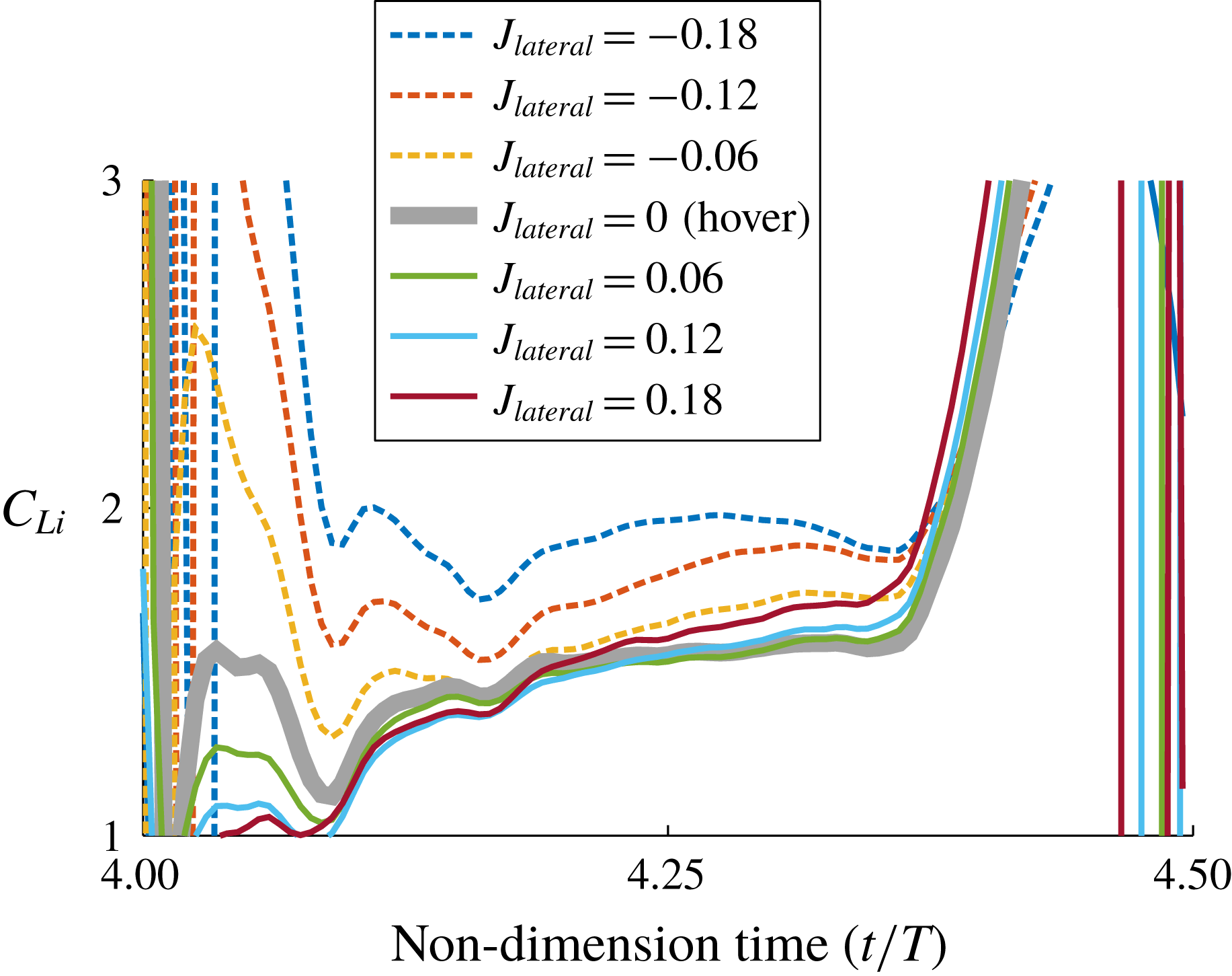
Figure 5 shows
 $C_{Li}$
during the upstroke (
 $4.0<t/T<4.5$
). Of note is
 $C_{Li}$
in cases with a negative
 $J_{lateral}$
, which scored higher values than the others. These elevations were maintained during the entire translational phase, clearly indicating a positive effect of a lateral wind on the aerodynamic force production. Another noteworthy feature is the positive
 $J_{lateral}$
cases, which showed nearly identical trends to that in the baseline case (
 $J_{lateral}=0$
). This suggests that the aerodynamic models (e.g. Sane & Dickinson Reference Sane and Dickinson2002, Han et al.
Reference Han, Chang, Kim and Han2015b
) could properly estimate the aerodynamic forces on the wing at least under these conditions, i.e. with the steady lateral inflow running from the wingtip to the wingroot at this range of
 $Re$
. It also should be highlighted that the time-course changes in
 $C_{Li}$
were not significant even in the negative
 $J_{lateral}$
cases. This indicates that the lift augmentations with
 $J_{lateral}<0$
were rarely associated with the ‘unsteadiness’, and the effect of lateral inflow could be predicted by the aerodynamic model with appropriate aerodynamic coefficients.
In order to see how much the forces quantitatively deviated from the ‘hover-based’ assumption, we further compared the measurements to the estimations of the aerodynamic model. Equation (3.5) shows the aerodynamic model for the lift, where the subscript
 $i$
denotes the
 $i$
th blade element:
 $$\begin{eqnarray}L_{quasi}=\underbrace{\frac{1}{2}\unicode[STIX]{x1D70C}C_{L}\mathop{\sum }_{i=1}^{N}(\dot{\unicode[STIX]{x1D719}}r_{i}+U_{lateral}\sin \unicode[STIX]{x1D719})^{2}c_{i}\unicode[STIX]{x0394}r}_{Translational~component}+\underbrace{\unicode[STIX]{x1D70C}C_{R}\mathop{\sum }_{i=1}^{N}(\dot{\unicode[STIX]{x1D719}}r_{i}+U_{lateral}\sin \unicode[STIX]{x1D719})\dot{\unicode[STIX]{x1D703}}c_{i}^{2}\unicode[STIX]{x0394}r}_{Rotational~component}.\end{eqnarray}$$
Here
 $C_{L}$
is a function of the angles of attack, but
 $C_{R}$
is a constant (refer to Han et al. (Reference Han, Kim, Chang and Han2015c
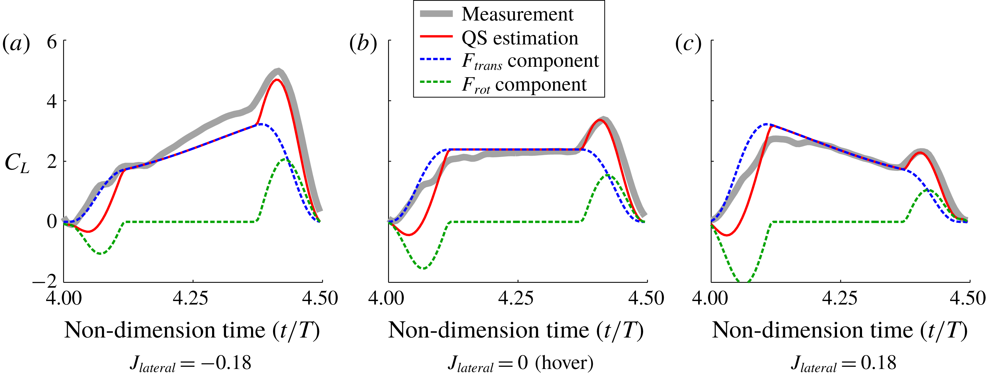
, Reference Han, Chang and Han2017) for details). Figure 6(a–c) compares those in the three selected cases of
 $J_{lateral}=-0.18$
, 0 (hover) and 0.18. We found that the aerodynamic model significantly underestimated the aerodynamic force when the wing moved to the left (
 $J_{lateral}=-0.18$
; figure 6
a). The greatest discrepancy appeared in the translational phase, which showed a mean difference of
 ${\sim}13.8\,\%$
. The rotational force component of the model also slightly underestimated the force during pitching-up wing rotation, thereby yielding
 ${\sim}18\,\%$
lower values throughout the wingbeat cycle. This is comparable to the other cases that only showed differences of
 ${\sim}5.8\,\%$
(
 $J_{lateral}=0$
) and
 ${\sim}7.2\,\%$
(
 $J_{lateral}=0.18$
); these mainly come from the small lift augmentations of the wing–wake interaction at the beginning of each stroke, which cannot be estimated by the aerodynamic models (Sane & Dickinson Reference Sane and Dickinson2002).
Measurements versus quasi-steady estimations in three
 $J_{lateral}$
cases.

Chordwise DPIV in the cross-sections from
 $0.2b$
to
 $0.9b$
at the right wing only.

Liang & Sun (Reference Liang and Sun2013) explained that a lateral wind running from the wingroot to the wingtip increases the axial velocity of the LEV, causing it to become more concentrated than that on the other wing due to the positive effect contributing to the Coriolis and/or centripetal accelerations (Lentink & Dickinson Reference Lentink and Dickinson2009a
,Reference Lentink and Dickinson
b
). This indicates that in this study, the LEV on a left wing would be much stronger than that on a right wing when an insect moves to the right or when the lateral wind comes from the right. Our examinations in the negative
 $J_{lateral}$
cases fairly well supported the previous interpretation (Liang & Sun Reference Liang and Sun2013). Both the higher level of
 $C_{Li}$
during the stroke (figure 5) and the underestimations by the quasi-steady aerodynamic model also seemed reasonable. However, the force in the positive
 $J_{lateral}$
cases, which had characteristics similar to those in hovering flight, needs another explanation. We inferred that the presence of a TV near the wingtip may shield the LEV from the direct influence of a lateral wind. The nonlinear response and phase shift of the aerodynamic force depending on a lateral gust (Jones & Yamaleev Reference Jones and Yamaleev2016), which implies extremely delicate aerodynamic characteristics under the lateral gust, indirectly support our inference in the positive
 $J_{lateral}$
cases. The
 $Re$
in this study, which initiates the spanwise flow and burst LEV with higher inertia, may promote the protection (Birch et al.
Reference Birch, Dickson and Dickinson2004; Garmann et al.
Reference Garmann, Visbal and Orkwis2013); the diffusivity of vortices at this
 $Re$
is substantially lower than that in the low
 $Re$
range (Kim & Gharib Reference Kim and Gharib2010).
Figure 7(a–c) describes LEV structures at the middle of the downstroke (
 $t/T=4.75$
). Each vorticity contour was normalized by the mean stroke velocity of the reference point, as shown in (3.6). MATLAB® was employed to reconstruct the fields in three dimensions.
 $$\begin{eqnarray}\hat{\unicode[STIX]{x1D714}}=\frac{\unicode[STIX]{x1D714}c}{\bar{U}_{tip}\hat{r}_{2}}=\frac{\unicode[STIX]{x1D714}c}{2\unicode[STIX]{x1D719}_{amp}R\hat{r}_{2}f}.\end{eqnarray}$$
The overall vorticity distribution in the baseline case (
 $J_{lateral}=0$
; figure 7
b) showed well-known LEV formations (e.g. Poelma et al.
Reference Poelma, Dickson and Dickinson2006). The wing built the swirl-like conical LEV system, which was smoothly widening along the wingtip. A dual-LEV system presenting high-
 $Re$
flow characteristics (Lu et al.
Reference Lu, Shen and Lai2006) was found at
 $0.5b$
and continued to the wingtip. The last section satisfying the Kutta condition was
 $0.7b$
. The LEV at this section was slightly lifted off and lengthened to the trailing edge, covering the entire upper surface of the wing section. At
 $0.8b$
and
 $0.9b$
, the LEVs eventually lifted off the surface. Trailing-edge vortices (TEVs) were found in these two outboard sections, implying TV development around these sections (refer to Kweon & Choi (Reference Kweon and Choi2010) and Han et al. (Reference Han, Chang and Han2016) for the sliced vortical structures of TVs).
When the wing moved to the left with
 $J_{lateral}=-0.18$
(figure 7
a), the LEV was remarkably concentrated. In contrast to the baseline case (figure 7
b), a stretched LEV was found at the outboard section (
 $0.8b$
) without a loss of vorticity. All of the sliced LEVs appeared to be completely stable, with no roll-up TEVs found even at the
 $0.9b$
section, suggesting that supplying additional flux along the spanwise direction reinforces the stability of the LEV system. Of note are RV traces of the previous half-stroke that went through the inboard sections up to
 $0.6b$
due to the steady lateral inflow. This also could increase the inflow velocity heading to the wing surface (as discussed later). The mean vorticity of the LEV was
 ${\sim}14\,\%$
higher than that of the baseline case, also indicating the additional contribution of the lateral inflow for both the aerodynamic lift and roll moment productions (Zhang & Sun Reference Zhang and Sun2010a
; Sun Reference Sun2014).
In contrast, the LEV on the wing with a positive
 $J_{lateral}$
experienced a strong interruption (figure 7
c). Only three inboard sections from
 $0.2b$
to
 $0.4b$
preserved the stable LEV. From
 $0.5b$
, the LEV was noticeably attenuated and started to lift off the surface. In the outboard sections from
 $0.6b$
to
 $0.9b$
, the LEV was completely broken down. The vortices were shed from the leading edge, and the strong TEV was found to have rolled up to the upper surface of the wing, implying a considerable TV growth (Kweon & Choi Reference Kweon and Choi2010; Han et al.
Reference Han, Chang and Han2016). The doughnut-shaped vortex ring and the downwash surrounded by the ring, therefore, only occupied a very narrow region within
 ${\sim}0.5b$
(Aono et al.
Reference Aono, Liang and Liu2008). The mean vorticity of the LEV in this case was
 ${\sim}7.3\,\%$
lower than that in the baseline case, properly reflecting such distorted structures. These sliced LEVs, however, still cannot provide an explanation of why the wing with a positive
 $J_{lateral}$
can produce a nearly identical level of aerodynamic force to that in the hovering condition. We noted a rapidly growing LEV in this case which reached the half-chord within
 $0.4b$
. This signifies that the LEV may be drastically bent to the trailing edge around
 $0.4b$
, becoming difficult to be collected by the chordwise cross-sectional DPIV. TEV traces rotating clockwise, signifying an excessive level of circulation beyond the Kutta condition, indirectly support the presence of the bent LEV and relatively more rapid flux on the suction side of the wing.
Figure 8(a–c) describes the ‘time-resolved’ vorticity distributions in three selected cases of
 $J_{lateral}=-0.18$
, 0 and 0.18, collected from the spanwise cross-sectional DPIV. Here, the laser sheet illuminated at the middle of the downstroke (
 $\unicode[STIX]{x1D719}=0^{\circ }$
) as the FOV. Hence, the wing gradually dived inside while penetrating the FOV at
 $t/T=4.75$
. The images were continuously recorded from
 $t/T=4.74$
to
 $t/T=4.81$
with 250 frames per second, resulting in sequential velocity fields on the FOV that steadily became distant from the wing surface. We reconstructed these time-varying structures into space with respect to their relative distances from the wing; figure 8(a–c) does not show the single instantaneous shots. Nonetheless, all the cases clearly show the LEV system that was composed of two vortical elements. In the baseline case (figure 8
b), for example, the main LEV was found to be stable up to
 ${\sim}0.7b$
. Beyond
 $0.7b$
, this LEV lifted off the surface and shifted to the TV along the spanwise flux. Near the wingtip, the minor vortex uniformly distributed along the leading edge. These all were in good agreement with the results of a previous study (Lu & Shen Reference Lu and Shen2008).
Spanwise DPIV reconstructed in space at the right wing only.

When the wing moved with
 $J_{lateral}=-0.18$
, the LEV system seemed to be pretty much stable (figure 8
a). The lifted-off LEV was found near
 ${\sim}0.85b$
, and a TV was fairly attenuated. The counterclockwise vorticity along the leading edge in figure 8(b), which mainly stemmed from a flow component running to the wingbase wrapping the LEV, rarely appeared in figure 8(a). This implies that a lateral wind could strengthen the LEV with cancelling out the flow component. The lateral wind rather resulted in trailing-edge shear layers (TESLs) alongside the shape of the wingbase. RV traces were found below the wingroot as several segments. In the case of
 $J_{lateral}=0.18$
(figure 8
c), the LEV was early lifted off the surface at
 ${\sim}0.45b$
, and a primary TV encroached into the suction side. However, the core of the TV did not appear to be sufficiently developed. The minor LEV was rather heavily formed along the leading edge similar to the shear layer. This also created secondary TVs in the outboard sections. Of note in this case is the slipped down primary TV. This augmented our inference about the bent LEV and the presence of the rapid flux.
Figure 9(a,c) shows sequential changes in the velocity magnitudes. The first row in figure 9 shows the fields at
 $t/T=4.765$
. Here
 $\unicode[STIX]{x1D719}$
, which also denotes the level of misalignment from the FOV (
 $\unicode[STIX]{x1D719}=0^{\circ }$
), was
 $-4.4^{\circ }$
. We found a large flux on the wing surface in the case of
 $J_{lateral}=0.18$
(figure 9
c). Most flux slipped sideward, heading in a direction opposite to the lateral wind. This was approximately five times faster than the lateral inflow, indicating sufficient lower pressure on the upper surface of the wing. When
 $t/T=4.78$
(
 $\unicode[STIX]{x1D719}=-7.85^{\circ }$
; second row in figure 9), the wings in the two cases of
 $J_{lateral}=-0.18$
and 0 clearly showed spanwise flux on the inboard sections. The outlines of TVs also slightly appeared at this phase. Here, the inflow running from the wingroot to the wingtip with
 $J_{lateral}=-0.18$
prolonged the spanwise flux and transferred the TV towards the wingtip. When
 $J_{lateral}=0.18$
(figure 9
c), however, most of the flux was heading toward the middle of the wing surface. The area which had shown a large flux on the wing surface completely changed to a ‘dead calm’, and became clearer at
 $t/T=4.79$
(
 $\unicode[STIX]{x1D719}=-11.6^{\circ }$
; third row in figure 9
c). This is in contrast to other cases which exhibited stable inflows over each LEV. When the wing dived more into
 $\unicode[STIX]{x1D719}=-14.5^{\circ }$
(
 $t/T=4.8$
; final row in figure 9), the LEV and TV became vividly observable. Increases in the inflow speed with stable LEVs were also clearly found in the two cases of
 $J_{lateral}=-0.18$
and 0 (figure 9
a,b). The LEV at
 $J_{lateral}=0.18$
, however, was strongly bent towards the trailing edge. The TV encroached by almost
 $0.5b$
, which was in line with our aforementioned inference.
Velocity magnitudes extracted from the near-wake footprints.

Lu & Shen (Reference Lu and Shen2008) investigated a LEV system on flapping wings using multi-slice digital stereoscopic PIV, and clarified that the LEV consists of intricate substructures which include a primary vortex and three minor vortices. They further investigated LEV behaviours depending on the three individual stroke phases of acceleration, maximum speed and deceleration. Among them, the overall structures around a decelerating wing (Lu & Shen Reference Lu and Shen2008) are fairly similar to that at
 $J_{lateral}=0.18$
. This not only includes the overall distribution of the flow field but also quantities such as the LEV descending to the trailing edge, the breakdown location of the LEV near
 ${\sim}0.5b$
, and the increment of the spanwise flow on the surface that is several times faster than that of the wingtip velocity. The nearly unchanged force production (Lu & Shen Reference Lu and Shen2008) was also in good agreement with our force measurements at
 $J_{lateral}>0$
, which did not show a noticeable difference from that in the baseline case (
 $J_{lateral}=0$
). This intricate LEV system, however, also clarified that employing the aerodynamic models to predict the force/moment did not have any physical basis.
3.2 Wing–wing and wing–body interactions under lateral inflow
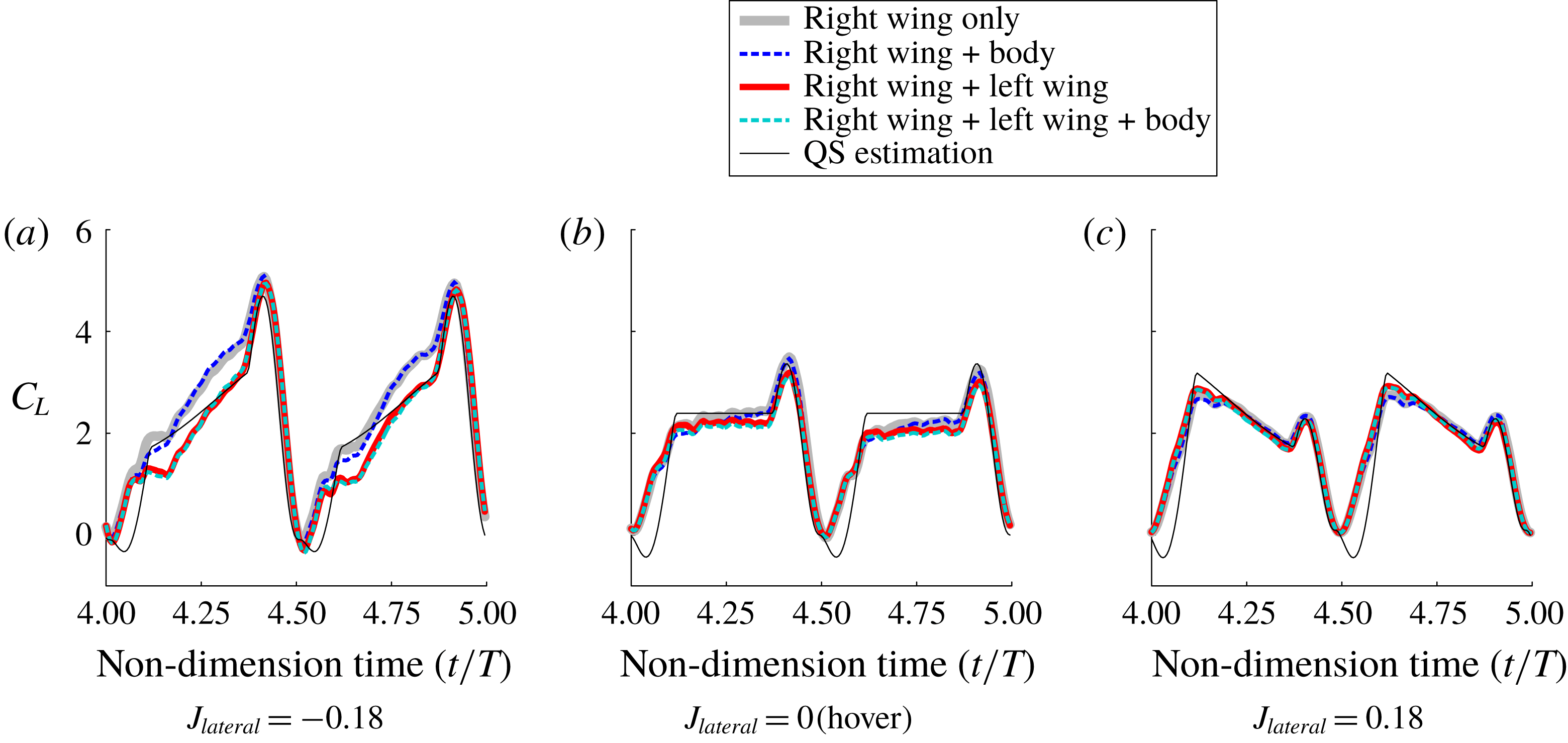
Figure 10(a–c) describes the wing–wing and wing–body interactions of
 $C_{L}$
in the three
 $J_{lateral}$
cases of
 $-0.18$
, 0 and 0.18. In the baseline case of
 $J_{lateral}=0$
(figure 10
b), the interactions did not show meaningful differences from each other. The wing–body interaction was nearly negligible, and wing–wing interaction only caused a relatively minor reduction in
 $C_{L}$
. This reduction, mainly due to the interaction of two wakes (Han et al.
Reference Han, Kim and Han2019), started from the middle of each stroke and was sustained until the end of the stroke. The quasi-steady aerodynamic model (Han et al.
Reference Han, Chang, Kim and Han2015b
) properly predicted
 $C_{L}$
in those cases except at the beginning of the wing stroke, at which the wing–wake interaction is dominant (Birch & Dickinson Reference Birch and Dickinson2003). The two flapping wings with
 $J_{lateral}=0.18$
(figure 10
c) resulted in small differences such as slightly higher peaks and rates of decline, but they were also nearly negligible. Accordingly, the aerodynamic model yielded an acceptable prediction, similar to the baseline case.
Time-varying
 $C_{L}$
in three
 $J_{lateral}$
cases depending on the interactions.

Of note is the wing–wing interaction when
 $J_{lateral}=-0.18$
(figure 10
a). This interaction substantially attenuated the aerodynamic force on the wing in the entire wingbeat cycle. It could be inferred that the lateral inflow that had already passed the flow field induced by the left wing (a contralateral wing) in advance gave rise to the attenuation. The right wing (a wing of interest), therefore, was not able to obtain the additional flux to reinforce the LEV, in contrast to the single-wing case. The fact that the aerodynamic model showed imperfect estimation capabilities until the wing reached the middle of each stroke indirectly supports our inference; an effect wake and/or downwash of the contralateral wing may be gradually reduced as the wings departed from the end of each stroke.
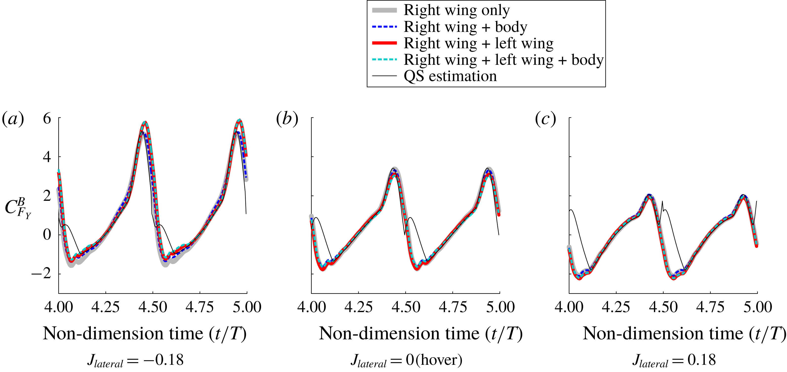
The wing–wing and wing–body interactions on
 $C_{F_{Y}}^{B}$
as shown in figure 11(a–c) are also in good agreement with the aforementioned interpretation. In contrast to both
 $C_{F_{Y}}^{B}$
at
 $J_{lateral}=0$
and 0.18, which were barely distinct from each other (figure 11
b,c), the wing–wing interaction at
 $J_{lateral}=-0.18$
(figure 11
a) produced slightly higher aerodynamic force during the pitching-up wing rotation. Note the
 $C_{L}$
in this circumstance, which also showed considerable attenuation (figure 10
a). This low-lift high-drag situation appeared to be associated with a lower effective angle of attack; the strong downwash induced by the right wing could reduce the effective angle of attack of the left wing to a certain level similar to a previous study (Han et al.
Reference Han, Kim and Han2019). Here, the lateral inflow running from the right wing may accelerate such a reduction because the inflow continuously pushes the downwash to the left wing.
Time-varying
 $C_{F_{Y}}^{B}$
in three
 $J_{lateral}$
cases depending on the interactions.

Figure 12 shows the cycle-averaged
 $C_{L}$
, clearly demonstrating the wing–wing and wing–body interactions on flapping wings under a lateral inflow. A notable difference was found for the case of negative
 $J_{lateral}$
. While the wing that did not undergo any interaction (black circles) produced lift up to
 ${\sim}28\,\%$
higher than that in hovering flight, the contralateral wing degraded this augmentation and eliminated most of the aerodynamic benefit. The degradation due to the wing–wing interaction covered the baseline case (
 $J_{lateral}=0$
) from the lower bound in this study (
 $J_{lateral}=-0.18$
), suggesting that the presence of the downwash induced by the contralateral wing may be the primary source to disturb the lift augmentation (Han et al.
Reference Han, Kim and Han2019). The wing–body interaction should also be highlighted, which attenuated the aerodynamic lift at a similar ratio in each case. This implies a disadvantage of the body with regard to generating aerodynamic lift at least under a lateral wind, in contrast to that in forward flight (Wan, Dong & Gai Reference Wan, Dong and Gai2015). We further found that the aerodynamic model predicted the lift at a similar level of wing–wing interaction. This suggests that previous studies using aerodynamic models to investigate flight dynamics (e.g. Faruque & Humbert Reference Faruque and Humbert2010a
,Reference Faruque and Humbert
b
, Cheng & Deng Reference Cheng and Deng2011, Kim et al.
Reference Kim, Han, Lee and Han2015) might reach proper interpretations even though they were somewhat incomplete with reference to the fluid physics.
Wingbeat-cycle-averaged
 $C_{L}$
.

Figure 13 displays the vorticity distributions influenced by the contralateral wing when
 $J_{lateral}=-0.18$
. In the chordwise cross-sectional DPIV (figure 13
a), the overall distributions appear to be similar to the single-wing case at
 $J_{lateral}=-0.18$
(figure 7
a). The LEV system appeared to be clearly stabilized by the lateral inflow, and only a small roll-up TEV was found at the wingtip. Such a distribution implies that the existence of the contralateral wing did not directly interrupt the additional flux along the spanwise direction. The vorticities of sliced LEV, however, were remarkably attenuated as compared to that in the single wing case. The attenuation was apparent in the inboard sections, and it was gradually recovered along the wingtip. The mean vorticity of the sliced LEVs was
 ${\sim}10.1\,\%$
lower than that in the single-wing case, which fairly reflected the difference of the lift productions in the two cases (figures 9
a and 12). Nearly disappeared RV traces, which had encroached to
 $0.6b$
in the single wing case, should also be highlighted. This implies that the downwash induced by the contralateral wing was strong enough to wash down the traces (Han et al.
Reference Han, Kim and Han2019).
Vorticity distributions in the two-winged case at
 $J_{lateral}=-0.18$
.

The same circumstance due to the wing–wing interaction was found in the spanwise DPIV (figure 13 b). Of note are the weakened TESL and completely disappeared RV traces, which were conspicuous in the single wing case. This implies the presence of a strong downwash developed by the contralateral wing. The LEV system remained identical to that in the single-wing case except for the lower level of the vorticity, also implying that the contralateral wing did not directly obstruct the spanwise flux of the LEV.
Some quantities extracted from the DPIV for the wing–wing interaction.

Figure 14 shows certain quantities that were extracted from the chordwise DPIV, exhibiting how the contralateral wing influenced the other wing in detail. Figure 14(a) shows the distributions of the effective angles of attack
 $\unicode[STIX]{x1D6FC}_{eff}$
, which were calculated by (3.7). Here,
 $u_{i}$
and
 $w_{i}$
denote the flow velocity in
 $x$
- and
 $z$
-directions (the vertical and horizontal directions in the FOV); these were collected in front of each cross-section
 $1.0c$
ahead. Parameter
 $N$
is the number of samples and
 $U_{section}$
is the stroke velocity at each FOV (see the schematics in figure 14
a for details).
 $$\begin{eqnarray}\unicode[STIX]{x1D6FC}_{eff}=\frac{1}{N}\mathop{\sum }_{i=1}^{N}\tan ^{-1}\frac{w_{i}}{U_{section}+u_{i}}.\end{eqnarray}$$
The wing in the baseline case (the single wing with
 $J_{lateral}=0$
) faced a slightly inclined headwind due to the downwash induced by the previous strokes; this was clearly observable near the wingbase. The single wing at
 $J_{lateral}=-0.18$
, in contrast, experienced a high
 $\unicode[STIX]{x1D6FC}_{eff}$
in most cross-sections. Several inboard sections even exceeded the geometrical angle of attack of
 $45^{\circ }$
, because of the presence of the RV induced by the previous half-stroke (Han et al.
Reference Han, Kim and Han2019). Of note is the reduced
 $\unicode[STIX]{x1D6FC}_{eff}$
due to the wing–wing interaction. The lack of
 ${\sim}5^{\circ }$
in most cross-sections appeared to be sufficient for reducing the aerodynamic force. Here, the downwash of the contralateral wing would be the main source of the lower
 $\unicode[STIX]{x1D6FC}_{eff}$
; the wing of interest (the right wing in this case) was continuously immersed in the downwash area formed by the other wing (the left wing in this case) with the lateral inflow.
Figure 14(b) displays the maximum values of the circulations
 $\unicode[STIX]{x1D6E4}^{\ast }$
in the three cases of the baseline (
 $J_{lateral}=0$
), the single wing at
 $J_{lateral}=-0.18$
and the two-winged configuration. We used here square boundaries centred on the pivot point to extract
 $\unicode[STIX]{x1D6E4}$
as shown in the schematic in figure 14(b), and normalized with the reference velocity and mean chord length as shown in (3.8):
 $$\begin{eqnarray}\unicode[STIX]{x1D6E4}^{\ast }=\frac{\unicode[STIX]{x1D6E4}}{\bar{U}_{tip}\hat{r}_{2}c}=\frac{\unicode[STIX]{x1D6E4}}{2\unicode[STIX]{x1D719}_{amp}R\hat{r}_{2}fc}.\end{eqnarray}$$
Because the
 $\unicode[STIX]{x1D6E4}^{\ast }$
calculation commonly fails to take the radial components into account, the means of
 $\unicode[STIX]{x1D6E4}^{\ast }$
in the two cases at
 $J_{lateral}=-0.18$
here appeared to be less than that in the baseline case for the cross-sections of
 $0.6b$
and
 $0.7b$
; this indicates that
 $\unicode[STIX]{x1D6E4}^{\ast }$
here did not directly reflect the lift forces. However, it was still clear that such a low
 $\unicode[STIX]{x1D6FC}_{eff}$
induced by the wing–wing interaction led to a considerable attenuation in
 $\unicode[STIX]{x1D6E4}^{\ast }$
. This attenuation was uniformly distributed throughout all cross-sections. One noteworthy feature is that
 $\unicode[STIX]{x1D6E4}^{\ast }$
gradually grew to the wingtip except at
 $0.9b$
, similar to that in the single-wing case at
 $J_{lateral}=-0.18$
. This implies that a certain positive outcome due to the spanwise flux may still be effective, and that the downwash of the contralateral wing may be the only source with which to reduce the aerodynamic force production with the lower
 $\unicode[STIX]{x1D6FC}_{eff}$
.
Figure 14(c) describes two velocity profiles collected from the surface DPIV results at
 $t/T=4.78$
, explaining how the wing–wing interaction interferes with the spanwise flux in the cores of the LEVs. Here,
 $t/T=4.78$
was not only the time instance when the wing reached
 $\unicode[STIX]{x1D719}=-7.8^{\circ }$
from the FOV, but also the spatial location coordinating each core of the LEV with the FOV in both cases. It was found that the flux was clearly weakened by the wing–wing interaction, except at
 $0.8b$
–
 $0.9b$
where the TV was growing. At
 $0.5b$
, for example, the interaction substantially depressed the flux in the core by as much as 63 %. Another feature was found near the trailing edge. In contrast to the single wing, which showed a gradual distribution of the flux running to the wingtip, the downwash induced by two flapping wings appeared to absorb the flux into the core of the doughnut-shaped vortex ring (e.g. Aono et al.
Reference Aono, Liang and Liu2008), thereby distorting the profiles to the wingroot. This also supports the presence of the strong downwash and its interruption of the lift production on the right wing (Han et al.
Reference Han, Kim and Han2019).
All of the aforementioned results clearly demonstrate that wing–wing and wing–body interactions are not negligible when a lateral wind is considered. In particular, the contralateral wing can considerably reduce the overall aerodynamic performance of the wing of interest; the downwash of the contralateral wing indirectly disturbs the inflow condition such as
 $\unicode[STIX]{x1D6FC}_{eff}$
, thereby reducing the LEV system on the other wing. Note that the aerodynamic lift was the major element of the roll moment on the body. This implies that the wing–wing interaction probably plays a marked role in flight stability.
3.3 Flapping counterforce (FCF) and static margin
In order to investigate the characteristics of basic flight stability, we employed a wingbeat-cycle-averaging approach as a linearization method. According to Zhang & Sun (Reference Zhang and Sun2010b ), this approach can be adopted when the wing mass is negligible and the wingbeat frequency is much higher than the natural frequency of the body. Most insects and FWMAVs adept at hovering satisfy these conditions (Nguyen et al. Reference Nguyen, Han and Han2017).
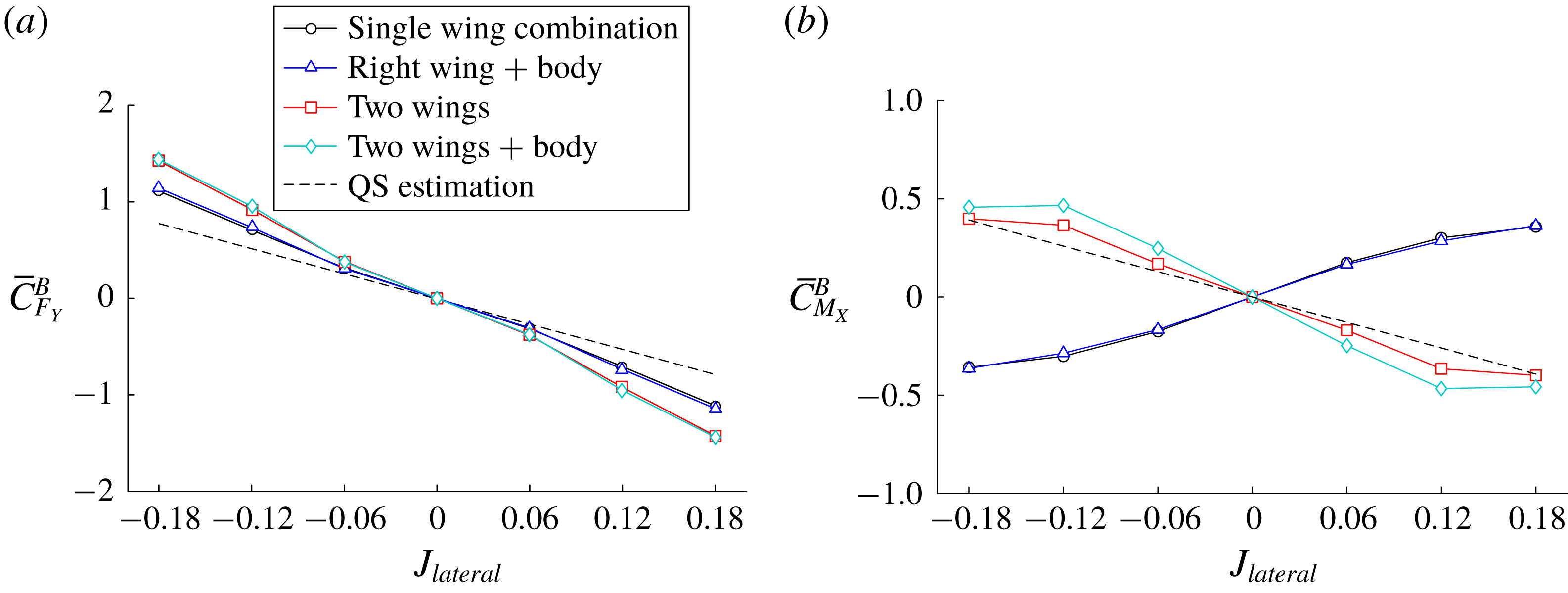
Figure 15 presents the mean values of the side force about the
 $Y^{B}$
-axis and of the roll moment about
 $X^{B}$
-axis compared with the quasi-steady estimations. Here, each value was individually combined with the single wing, single wing and body, two wings, and two wings and body with respect to the speed of lateral inflow. The values in the negative sideward ratio were used for those on the other wing with the negative sign as mentioned previously.
Wingbeat-cycle-averaged aerodynamic coefficients with the quasi-steady estimation.

In figure 15(a), it was found that regardless of the interactions, the stability derivatives along the
 $Y^{B}$
-direction indicated negative values. This signifies that the forces produced by the two wings were consequently heading in the opposite direction to the lateral inflow, and this model had static stability in the lateral direction (Sun Reference Sun2014). This also clarifies that the FCF (Cheng & Deng Reference Cheng and Deng2011), which describes inherent damping in insect flight dynamics, was quite valid along the
 $Y^{B}$
-axis. In fact, the FCF can also be explained by simple arithmetic at least in the event of a lateral wind. With regard to wings in hover, a lateral wind adds a small sinusoid to the stroke velocity, expressed as
 $U_{ref}+U_{lateral}\sin \,\!\unicode[STIX]{x1D719}$
. The aerodynamic force is directly proportional to its square, and this square always holds the second term,
 $2U_{ref}U_{lateral}\sin \,\!\unicode[STIX]{x1D719}$
, in the corresponding expansions. In contrast to the other terms, which practically cancel out due to the opposite directions on two ‘mirrored’ wings with a bisymmetry, this term stays and behaves only as an operator, causing imbalances and damping (counterforce). The other components in the aerodynamics model, including the rotational force and the added mass contribution on the two wings, also cancel out each other.
One interesting point in the measurements is the slightly greater derivative than that of the estimation. Concerning the cancellation relationship of the other components, it can be concluded that the wing–wake interaction, which cannot be predicted by the quasi-steady aerodynamic model (Sane & Dickinson Reference Sane and Dickinson2002; Han et al.
Reference Han, Kim, Chang and Han2015c
), was the only source providing such a greater derivative. This stands in contrast to the destabilizing effect of wing–wake interaction on the longitudinal stability (Bluman & Kang Reference Bluman and Kang2017). The steeper curves in the two wing–wing interaction cases should also be highlighted. This appeared to come from the low-lift high-drag situation with the lower value of
 $\unicode[STIX]{x1D6FC}_{eff}$
, which was expressed as the slightly higher peak before the stroke reversal (figure 11
a). This clearly indicates that wing–wing interaction improves the lateral stability.
Figure 15(b) shows the combinations for body roll moments and the quasi-steady estimation. Here, we borrowed the location of the CG of the targeted insect, the hawkmoth Manduca sexta, which had the CG at
 ${\sim}0.21b$
from the cross-point on the shoulder line (Ellington Reference Ellington1984; Kim et al.
Reference Kim, Han, Lee and Han2015). This approach cannot guarantee accurate quantities in contrast to other studies (Faruque & Humbert Reference Faruque and Humbert2010a
,Reference Faruque and Humbert
b
; Zhang & Sun Reference Zhang and Sun2010a
; Cheng & Deng Reference Cheng and Deng2011; Sun Reference Sun2014; Kim et al.
Reference Kim, Han, Lee and Han2015), because of its simplified motion profiles and other minor assumptions such as the rigid wing. Nonetheless, it was still clearly seen that the positive roll moment derivative due to the lift augmentation, which was found in the single-wing combination, was completely inverted when the wing–wing interaction was considered. The two roll moment derivatives with this interaction, therefore, had a similar trend to that of the quasi-steady estimation. This implies that wing–wing interaction could play a positive role in static stability in the roll direction.
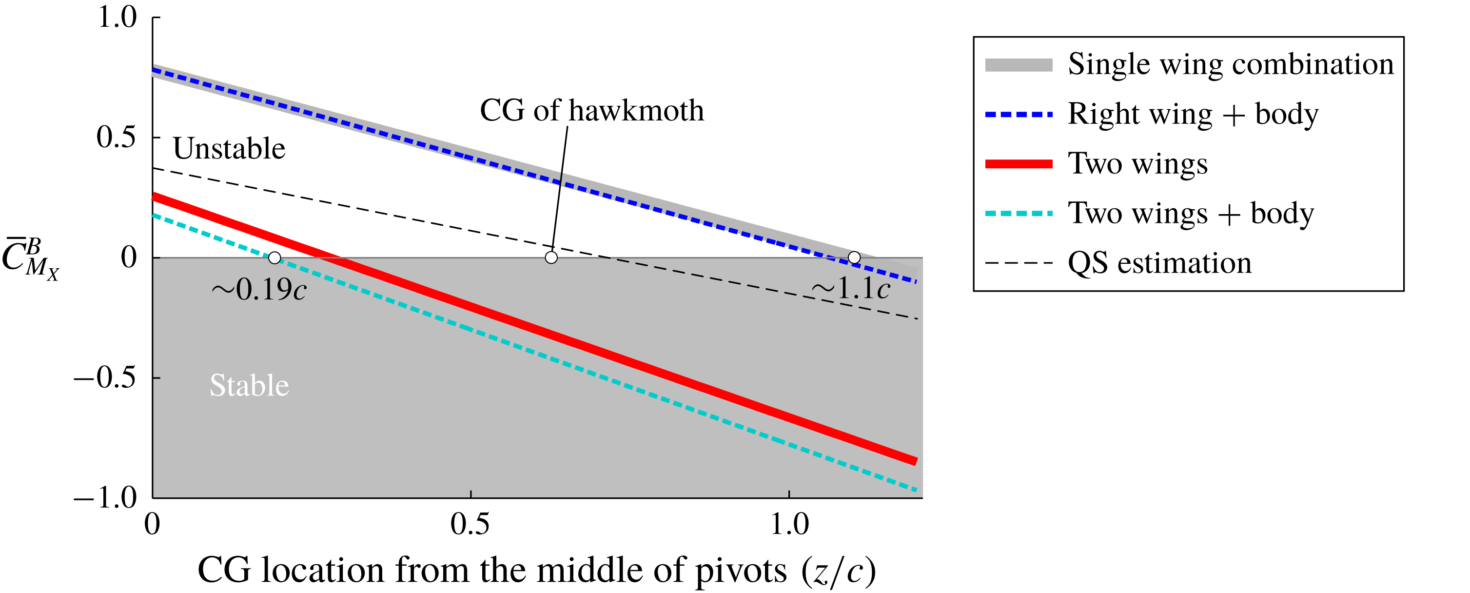
We further calculated the roll moments with respect to arbitrary CG locations on the
 $Z^{B}$
-axis. Because the moments in this study were based on the cross-point of the shoulder line and the
 $Z^{B}$
-axis (the middle of two pivots) as noted earlier, some relationships pertaining to roll moment stability can be expressed as a function of the distance from the CG with the cycle-averaged side force and roll moment, as shown in (3.9). This calculation, stemming from (2.2), can also provide information about the neutral points and static margin in the roll direction.

Figure 16 describes the cycle-averaged roll moments with respect to the CG locations at
 $J_{lateral}=0.12$
; we avoid using
 $J_{lateral}=0.18$
because it lost linearity as shown in figure 15(b). The distance
 $d$
was normalized by the mean chord length
 $c$
, heading downward from the middle of two pivots (reference point). The negative roll moment signifies static stability, and the values of
 $d$
when the roll moments equal zero imply the neutral point in each case.
Changes in
 $\bar{C}_{M_{X}}^{B}$
with respect to arbitrary CG locations.

All of these measurements showed slightly greater declines than that of the quasi-steady estimation, most likely due to the stronger side force with the wing–wake interaction. Among these outcomes, the results without wing–wing interaction started at quite high levels, indicating that the system requires a CG at a long distance from the pivot to acquire stability. The wing–body interaction in these cases slightly accelerated the negative gradient, but it did not appear to be sufficient to make the system stable. This instability originated from the lift augmentation on the contralateral wing (the far-side wing from the source of the lateral wind), which was enhanced by the increase in the axial velocity, as noted in previous studies (Zhang & Sun Reference Zhang and Sun2010a
; Zhang et al.
Reference Zhang, Wu and Sun2012). Of note is that the wing–wing interaction substantially attenuated these amounts of roll moment. The combination of wing–wing and wing–body interactions intensified this trend. These only required
 ${\sim}0.19c$
to ensure static stability; these were even better than the values of the quasi-steady estimation, which had a neutral point near the CG of the hawkmoth of
 ${\sim}0.65c$
(Ellington Reference Ellington1984). These features were also found in the different
 $J_{lateral}$
values, supporting a positive role of wing–wing interaction in the lateral stability.
As stated above, several studies focusing on flight dynamic characteristics (Faruque & Humbert Reference Faruque and Humbert2010a
,Reference Faruque and Humbert
b
; Cheng & Deng Reference Cheng and Deng2011; Kim & Han Reference Kim and Han2014; Kim et al.
Reference Kim, Han, Lee and Han2015) employed quasi-steady aerodynamic models. Faruque & Humbert (Reference Faruque and Humbert2010a
,Reference Faruque and Humbert
b
), and Cheng & Deng (Reference Cheng and Deng2011) only adopted the
 $F_{trans}$
component to calculate the aerodynamic force and moment, whereas Kim & Han (Reference Kim and Han2014) and Kim et al. (Reference Kim, Han, Lee and Han2015) used full descriptions of the model, including
 $F_{trans}$
,
 $F_{rot}$
and the added mass contribution
 $F_{added}$
. Nonetheless, all results relying on these models argued that the lateral motion is stable (the roll moment derivative is negative), which appears to be fairly similar to our QS estimations. The Navier–Stokes simulation by Sun and colleagues (e.g. Zhang & Sun Reference Zhang and Sun2010a
, Zhang et al.
Reference Zhang, Wu and Sun2012) resulted in positive roll moment derivatives, implying instability in the lateral direction. This was in good agreement with our measurements of the isolated wing–wing interaction. We found that the wing–wing interaction could lead to a favourable effect on the lateral stability of a flapping-wing system. The neutral points of this model, which were located at
 $1.1c$
(the single-wing combination),
 $1.06c$
(the single-wing combination with the body),
 $0.28c$
(two wings) and
 $0.19c$
(two wings and the body) below the pivot point, further clarify that the wing–wing interaction could allow the CG to be much closer to the pivot point, probably giving superior manoeuvrability to insects in other directions.
4 Conclusion
In this paper, we examined the aerodynamic characteristics of an insect model under a uniform lateral inflow using a dynamically scaled-up robotic manipulator and a servo-driven towing tank. The results from the single-wing cases revealed that a lateral wind coming from the wingroot noticeably augmented the aerodynamic force and moment. The DPIV found a concentrated LEV system which distributed over the entire surface except near the wingtip. The inflow running in the opposite direction, however, did not bring on noticeable differences in the aerodynamic force/moment. This created strong imbalances in the force and moment on two wings and flight instability similar to that found in previous studies. We found that the wing–wing interaction neutralized all such augmentations from a lateral wind. The DPIV revealed that the strong downwash induced by the contralateral wing depressed the effective angles of attack on the other wing, thereby degrading the aerodynamic force and moment. Further investigation revealed that the wing–wing interaction can lead to a favourable effect on the lateral flight stability. The low-lift high-drag situation due to the wing–wing interaction resulted in larger side force gradients and reinforced the stability as compared to that in the FCF estimation. The roll moment derivatives calculated with the CG of the model hawkmoth were completely reversed, and the static margin obtained with the arbitrary CG location was substantially improved by the wing–wing interaction.
Acknowledgements
This work was supported by a grant from the National Research Foundation of Korea (NRF) funded by the Korean government (Ministry of Science and ICT) (nos. NRF-2016R1A6A3A11931608 and 2017R1A2B4005676).