
1. Introduction
Drop–drop coalescence is fundamentally a surface-tension-driven phenomenon, leading to the merging of two control mass systems into a single unit to minimize the total surface energy. From the early development of the subject, the dynamics of coalescence at drop–drop interfaces or drop–pool interfaces has been widely studied, in an effort to explain a plethora of natural phenomena such as the formation of mist, size variations of rain droplets in the atmosphere and fusion of raindrops into water reservoirs (Qian & Law Reference Qian and Law1997; Blanchette & Bigioni Reference Blanchette and Bigioni2009; Tang, Zhang & Law Reference Tang, Zhang and Law2012). In more recent years, there has been a growing interest in investigating the interactive dynamics of droplet arrays in engineered devices for manipulating various chemical and biological processes (Anna Reference Anna2016; Sánchez Barea, Lee & Kang Reference Sánchez Barea, Lee and Kang2019; Panigrahi et al. Reference Panigrahi, Santra, Banuprasad, Das and Chakraborty2021; Santra & Chakraborty Reference Santra and Chakraborty2021). Furthermore, in industrial applications like ink-jet printing, surface coating and fuel injectors, frequent events of drop collision appear inevitable (Aarts et al. Reference Aarts, Lekkerkerker, Guo, Wegdam and Bonn2005; Tang et al. Reference Tang, Zhang and Law2012; Peng et al. Reference Peng, Luo, Zuo, Yan and Bai2018; Varma et al. Reference Varma, Saha, Mukherjee, Bandopadhyay, Kumar and Chakraborty2020). In oil–water segregation processes, for instance, the coalescence of water droplets is preferred for efficient sedimentation of the dispersed phase (Kavehpour Reference Kavehpour2015).
Drop–drop or drop–interface collisions may lead to a variety of events such as coalescence, bouncing or splash, depending on the approaching speed and separation distance (Rein Reference Rein1993; Qian & Law Reference Qian and Law1997; Tang et al. Reference Tang, Zhang and Law2012; Cong et al. Reference Cong, Qian, Wang and Lin2020). Experimental studies (Qian & Law Reference Qian and Law1997; Tang et al. Reference Tang, Zhang and Law2012) conducted for various drop-impact conditions show that a low relative speed and small separation distance are the most favourable condition for coalescence. In contrast, a higher speed can lead to either drop bouncing or splash. As the drop approaches a liquid surface, the medial thin film gradually drains out, and a tiny connecting bridge (or neck) forms. If the capillary bridge radius  $({\bar{R}_n})$ turns out to be much larger than the viscous length scale, i.e.
 ${\bar{R}_n} \gg {\bar{l}_v} = {\mu ^2}/\rho \gamma $, the local flow remains effectively inviscid, as appropriate for various biological and chemical processes involving aqueous systems (where
 ${\bar{l}_v}\sim 10\ \textrm{nm}$). In a significant development, Eggers, Lister & Stone (Reference Eggers, Lister and Stone1999) mathematically modelled the bridge evolution in the inertio-capillary regime by scaling the interfacial stress with the inertial stress and inferred that the bridge growth follows a power law:
 ${\bar{R}_n} \propto {\bar{t}^{1/2}}$, wherein
 ${\bar{R}_n}$ and
 $\bar{t}$ are bridge radius and time in dimensional forms, respectively. While subsequent experimental and numerical studies conducted by several researchers (Menchaca-Rocha et al. Reference Menchaca-Rocha, Martínez-Dávalos, Núñez, Popinet and Zaleski2001; Duchemin, Eggers & Josserand Reference Duchemin, Eggers and Josserand2003; Wu, Cubaud & Ho Reference Wu, Cubaud and Ho2004) seemed to agree well with this scaling law, deviations were observed in the later experiments of Thoroddsen, Takehara & Etoh (Reference Thoroddsen, Takehara and Etoh2005). These discrepancies primarily stemmed from the finite radius of the inertial bridge as opposed to the considerations of more idealized theories, which may, in principle, be rationalized by delving into the detailed dynamics of the relatively less addressed inertio-capillary regime. For instance, expansion of the capillary bridge may further facilitate mass transfer between the liquid bodies and initiate the droplet merging process. In addition, this may also set in partial coalescence, generating a secondary drop in the process that may exhibit self-similar dynamic events at different stages, which is commonly termed a coalescence cascade. As demonstrated by Chen, Mandre & Feng (Reference Chen, Mandre and Feng2006) and later by Ray, Biswas & Sharma (Reference Ray, Biswas and Sharma2010), partial coalescence mostly occurs in an inertio-capillary-dominated regime, while the dominance of viscous and gravity effects mostly results in complete coalescence.
The physics of morpho-dynamic evolution during partial or complete coalescence is known to be intriguing. From fundamental theoretical considerations, the capillary wave generated at the liquid bridge is likely to traverse over the drop surface and bring in topological modulations by giving rise to cylindrically shaped topologies. Earlier, it was argued that the secondary drop pinches due to the Rayleigh–Plateau instability of this long cylindrical structure. Later on, Blanchette & Bigioni (Reference Blanchette and Bigioni2006) analysed this problem numerically and showed that the vertical and horizontal collapse rates determine the pinch-off as the cylindrical structures are not long enough to result in Rayleigh–Plateau instability. These findings revealed that the resulting morpho-dynamics over local scales may turn out to be significantly more involved as compared to the insights provided by the classically postulated instability mechanisms. The situation gets significantly more involved when partial coalescence occurs. While partial coalescence is more common in drop–pool interactions, unequal drop size is also a strong influencing factor favouring the same during multi-drop interactions. Zhang, Li & Thoroddsen (Reference Zhang, Li and Thoroddsen2009) offered experimental insights into the process and obtained a threshold diameter ratio of the parent drops to be around 1.55, beyond which pinch-off phenomena occur. They also observed a monotonic increase in the said ratio with an increase in the fluid viscosities. More intensive analysis of the mechanism responsible for the transition from partial to complete coalescence and the role of viscous effect therein has been put forward in the recent work of Deka et al. (Reference Deka, Biswas, Chakraborty and Dalal2019).
While the studies mentioned above offered comprehensive mechanistic insights into the drop coalescence phenomenon, the role of external fields, such as electric field (Johnson Reference Johnson1968; Higuera Reference Higuera2006; Welch & Biswas Reference Welch and Biswas2007; Karyappa, Naik & Thaokar Reference Karyappa, Naik and Thaokar2016; Mandal, Bandopadhyay & Chakraborty Reference Mandal, Bandopadhyay and Chakraborty2016b; Poddar et al. Reference Poddar, Mandal, Bandopadhyay and Chakraborty2019; Vlahovska Reference Vlahovska2019; Behera & Chakraborty Reference Behera and Chakraborty2020; Su et al. Reference Su, Zhang, Luo and Yi2020; Kahali, Santra & Chakraborty Reference Kahali, Santra and Chakraborty2022), magnetic field (Kahkeshani & Di Carlo Reference Kahkeshani and Di Carlo2016; Rowghanian, Meinhart & Campàs Reference Rowghanian, Meinhart and Campàs2016) and acoustic field (Simon et al. Reference Simon, Sapozhnikov, Khokhlova, Crum and Bailey2015), in the same necessitates further advancements of theoretical understanding via providing complementary multi-physics perspectives. Such insights appear to be imperative for advancing several emerging industrial and microfluidic applications in which external-field-mediated coalescence may be utilized for the desired functionalities such as efficient demulsification (Eow et al. Reference Eow, Ghadiri, Sharif and Williams2001; Ahn et al. Reference Ahn, Agresti, Chong, Marquez and Weitz2006; Mhatre et al. Reference Mhatre, Vivacqua, Ghadiri and Kermani2015b; Nie et al. Reference Nie, Ma, Yang and Yin2021). Fundamentally, electric-field-mediated effects may induce dielectrophoretic motion of drops to enhance their speed of approach as a precursor to coalescence. However, such dielectrophoresis-based considerations alone appear to be inadequate in providing conclusive evidence as to whether influences of external field would lead to sufficient conditions for coalescence or not, and conflicting observations in this regard have been reported in the literature as well (Bird et al. Reference Bird, Ristenpart, Belmonte and Stone2009; Ristenpart et al. Reference Ristenpart, Bird, Belmonte, Dollar and Stone2009). Previous works, nevertheless, suggested that the angles of the Taylor cones formed at the contact region may provide a critical influence on the consequent dynamic outcome, irrespective of the nature of the external field. By conducting experimental and theoretical analysis for a drop–air system, Bird et al. (Reference Bird, Ristenpart, Belmonte and Stone2009) demonstrated that the drops may not coalesce for a cone angle above 30.8°. However, one recent experimental study by Anand et al. (Reference Anand, Roy, Naik, Juvekar and Thaokar2019) revealed that the critical cone angle can be as small as 19° for oil-based emulsions. These studies duly evidenced the importance of the initial separation distance, typically conditions in which the parent drops deform to an extent to obviate their coalescence.
Electrically mediated drop coalescence (or electro-coalescence) has emerged as a very active research topic in recent times, particularly keeping in purview its growing technological importance and the associated unaddressed scientific questions. These reported studies, however, were mostly restricted to the viscous-dominated regime (Mousavichoubeh, Ghadiri & Shariaty-Niassar Reference Mousavichoubeh, Ghadiri and Shariaty-Niassar2011; Mousavi, Ghadiri & Buckley Reference Mousavi, Ghadiri and Buckley2014; Mhatre et al. Reference Mhatre, Vivacqua, Ghadiri and Kermani2015b; Santra, Mandal & Chakraborty Reference Santra, Mandal and Chakraborty2018; Santra et al. Reference Santra, Sen, Das and Chakraborty2019; Li et al. Reference Li, Wang, Vivacqua and Wang2020; Das, Dalal & Tomar Reference Das, Dalal and Tomar2021). Garzon, Gray & Sethian (Reference Garzon, Gray and Sethian2018), in a more recent study, examined the partial coalescence phenomena of drops subjected to an electric field and analysed the consequent alterations in the size of the satellite drop. However, their model did not discuss viscous effects nor the role of the sizes of the parent drops. Accordingly, several open questions on the electrically mediated coalescence of drops remain unaddressed, in particular, the interplay of various forces governing the resulting morpho-dynamics in the inertio-capillary regime. Here, we analyse the coalescence dynamics of unequal-sized drop pairs in the inertio-capillary-dominated flow regime by applying a uniform electric field. In particular, we aim to bring out the role of the relative physical properties of the different phases in the consequent morphological evolution, including the cascaded formation of secondary drops and the associated pinch-off phenomena. These results offer the multi-physics perspective of coalescence dynamics under the interplay of electrodynamics and hydrodynamics over interfacial scales, with particular reference to the critical conditions leading to the onset of various unstable modes that have hitherto remained unexplored.
2. Problem description
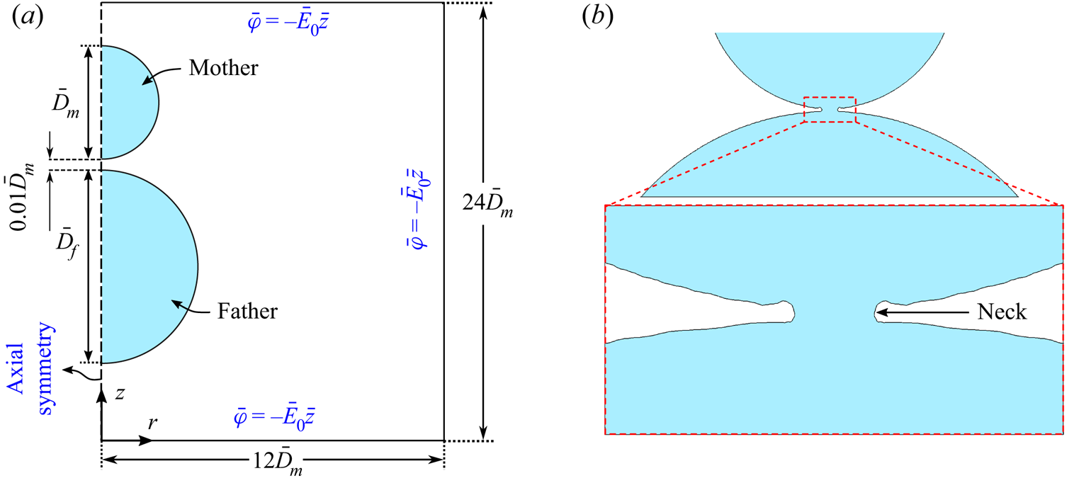
We consider two closely placed drops of identical fluids that are about to coalesce, suspended in a carrier fluid, as shown in figure 1(a). The diameters of the mother drop and father drop are  ${\bar{D}_m}$ and
 ${\bar{D}_f}$, respectively, and the parent ratio is defined by
 $\beta = {\bar{D}_f}/{\bar{D}_m}$. Material properties of the drop phase, i.e. density, viscosity, electrical permittivity and electrical conductivity, are denoted by
 ${\bar{\rho }_i}$,
 ${\bar{\mu }_i}$,
 ${\bar{\varepsilon }_i}$ and
 ${\bar{\sigma }_i}$, respectively, whereas the same properties of the suspending medium are denoted by
 ${\bar{\rho }_e}$,
 ${\bar{\mu }_e}$,
 ${\bar{\varepsilon }_e}$ and
 ${\bar{\sigma }_e}$, respectively. The overbar is used to denote dimensional quantities. A uniform electric field
 $({\bar{\boldsymbol{E}}_0})$ is applied along the vertically upward direction. The gravitational field
 $(\bar{\boldsymbol{g}})$ as well as dielectrophoretic interactions favour drop collision. The initial gap between the drops is kept negligibly small
 $(\Delta \bar{h} \approx 0.01{\bar{D}_m})$, allowing the completion of film drainage within a short time. Because of an extremely slow approach speed, the coalescence dynamics remains unaffected due to additional artefacts on account of drop impact.
(a) Schematic of the axisymmetric computational domain used to study the coalescence of drop pairs. A mother drop of diameter  ${\bar{D}_m}$ is kept near a father drop of size
 ${\bar{D}_f}$ with a gap of 0.01
 ${\bar{D}_m}$ between them. An external electric field
 ${\bar{\boldsymbol{E}}_0} ={-} \bar{\boldsymbol{\nabla}}\bar{\varphi }$ is applied along the vertically upward direction. (b) Structure of the neck obtained at time t = 0.03.

Figure 1(b) schematically illustrates a typical liquid bridge created after the successful drainage of the film. We investigate in detail the morphological evolution post-drainage via using a numerical approach, as detailed subsequently. We use an axisymmetric coordinate system (r, z) to study the transport processes in the domain having a sectional height of  $24{\bar{D}_m}$ and width of
 $12{\bar{D}_m}$. The computational domain is taken to be sufficiently large to avoid the boundary effects on the drop dynamics. The left side of the domain boundary is subjected to symmetric boundary conditions for the velocity and the electric potential. Neumann boundary condition for the velocity is imposed on the other sides of the domain. For electric potential,
 $\bar{\varphi } ={-} {\bar{E}_0}\bar{z}$ is applied at all the boundaries except for the symmetry axis, where
 $\bar{\varphi}$ and
 $\bar{E}_0$ are the electric potential and magnitude of the applied electric field, respectively. The velocity field
 $\bar{\boldsymbol{u}}({\bar{u}_r},{\bar{u}_z})$ created due to the combined action of the capillary wave and the electric field is governed by continuity and equivalent one-fluid Navier–Stokes equation:
 \begin{gather}\bar{\boldsymbol{\nabla }}\boldsymbol{\cdot
}\bar{\boldsymbol{u}} =
0,\end{gather}
 \begin{gather}\bar{\rho }(c)\left( {\frac{{\partial \bar{\boldsymbol{u}}}}{{\partial \bar{t}}} + \bar{\boldsymbol{u}}\boldsymbol{\cdot }\bar{\boldsymbol{\nabla }}\bar{\boldsymbol{u}}} \right) ={-} \bar{\boldsymbol{\nabla }}\bar{p} + \bar{\boldsymbol{\nabla }}\boldsymbol{\cdot }{\bar{\boldsymbol{\tau }}_v} + \gamma \bar{\kappa }\boldsymbol{n}{\bar{\delta }_s} + {\bar{\boldsymbol{F}}_E} + \bar{\rho }(c)\bar{\boldsymbol{g}}.\end{gather}
Here  $\bar{p}$ denotes the pressure and
 ${\bar{\boldsymbol{\tau }}_v} = \bar{\mu }(c)\{ \bar{\boldsymbol{\nabla}}\bar{\boldsymbol{u}} + {(\bar{\boldsymbol{\nabla}}\bar{\boldsymbol{u}})^T}\}$ is the viscous stress tensor. Using a one-fluid formulation the material properties like density
 $\bar{\rho }(c)$ and viscosity
 $\bar{\mu }(c)$ are interpolated as
 $\bar{\rho } = c{\bar{\rho }_i} + (1 - c){\bar{\rho }_e}$ and
 $\bar{\mu } = c{\bar{\mu }_i} + (1 - c){\bar{\mu }_e}$, respectively, where the volume fraction c(r, z, t) is a spatio-temporal variable, which satisfies the advection equation that is reminiscent of the kinematic boundary condition:
 \begin{equation}\frac{{\partial c}}{{\partial \bar{t}}} + \bar{\boldsymbol{u}}\boldsymbol{\cdot }\bar{\boldsymbol{\nabla}}c = 0.\end{equation}
Here, c takes the value of 1 and 0 for the drop phase and carrier phase, respectively.
In (2.2),  $\gamma \bar{\kappa }\boldsymbol{n}{\bar{\delta }_s}$ represents the volumetric surface tension force, where γ is the interfacial tension between the two phases,
 $\bar{\kappa}$ is the curvature,
 $\boldsymbol{n}$ is the normal unit vector and
 ${\bar{\delta }_s}$ is the smoothed Dirac delta function. Likewise, the electric force is expressed in terms of its volumetric density,
 ${\bar{F}_E}$ (Melcher & Taylor Reference Melcher and Taylor1969):
 \begin{equation}{\bar{\boldsymbol{F}}_E} = \bar{\boldsymbol{\nabla }}\boldsymbol{\cdot }{\bar{\boldsymbol{\tau }}_M} = {\bar{q}_v}\bar{\boldsymbol{E}} - {\textstyle{1 \over 2}}{\bar{E}^2}\bar{\boldsymbol{\nabla}}\bar{\varepsilon }(c),\end{equation}
where  ${\bar{\boldsymbol{\tau }}_M} = \bar{\varepsilon }(c)(\boldsymbol{\bar{E}\bar{E}} - {\bar{E}^2}\boldsymbol{I}/2)$ is the Maxwell stress tensor,
 $\bar{\boldsymbol{E}}$ is the electric field and
 ${\bar{q}_v}$ is the charge per unit volume. The first term on the right-hand side of (2.4) represents the Columbic force and the second term represents the dielectrophoretic force. The electrostriction effects are not considered to contribute towards the volumetric force, assuming homogenous and incompressible bulk fluid phase (Melcher & Taylor Reference Melcher and Taylor1969; Hua, Lim & Wang Reference Hua, Lim and Wang2008). The interfacial stress, essentially a combined consequence of the viscous, capillary and Maxwell stresses, needs to satisfy the following force balance constraint:
 \begin{equation}||\boldsymbol{n}\boldsymbol{\cdot }{\bar{\boldsymbol{\tau }}_v}||+ ||\boldsymbol{n}\boldsymbol{\cdot }{\bar{\boldsymbol{\tau }}_M}||= ||\boldsymbol{n}\boldsymbol{\cdot }\bar{p}\boldsymbol{I}||+ \gamma \bar{\kappa },\end{equation}
where  $||{\ }||$ represents the jump of a physical quantity at the interface.
The electrical stresses may be estimated by noting that the electric field is divergence-free  $(\bar{\boldsymbol{\nabla}} \times \bar{\boldsymbol{E}} = 0)$, and thus can be expressed in the form of electric potential,
 $\bar{\boldsymbol{E}} ={-} \bar{\boldsymbol{\nabla}}\bar{\varphi }$. It further satisfies the Gauss law, so that
 \begin{equation}\bar{\boldsymbol{\nabla }}\boldsymbol{\cdot }(\bar{\varepsilon }(c)\bar{\boldsymbol{E}}) = {\bar{q}_v}.\end{equation}
Expressed in terms of the electrical potential, it reads  $- \bar{\boldsymbol{\nabla }}\boldsymbol{\cdot }(\bar{\varepsilon }(c)\bar{\boldsymbol{\nabla}}\bar{\varphi }) = {\bar{q}_v}$. Transport of the volumetric charge
 ${\bar{q}_v}$ is governed by the Ohmic charge conduction, surface charge convection and transient charge relaxation. The resulting transport equation reads (Melcher & Taylor Reference Melcher and Taylor1969)
 \begin{equation}\frac{{\partial {{\bar{q}}_v}}}{{\partial \bar{t}}} + \bar{\boldsymbol{\nabla }}\boldsymbol{\cdot }({\bar{q}_v}\bar{\boldsymbol{u}}) + \bar{\boldsymbol{\nabla }}\boldsymbol{\cdot }\bar{\boldsymbol{J}} = 0,\end{equation}
where  $\bar{\boldsymbol{J}} = (\bar{\sigma }\bar{\boldsymbol{E}}\textrm{)}$ is the current density and
 $\bar{\boldsymbol{\nabla }}\boldsymbol{\cdot }\bar{\boldsymbol{J}}$ delineates the Ohmic conduction.
In several physical systems of interest including vegetable oils, alcohols, crude oils and several coolants used in industrial practice (Corach, Sorichetti & Romano Reference Corach, Sorichetti and Romano2012; Valantina et al. Reference Valantina, Susan, Bavasri, Priyadarshini, Saraswathi and Suriya2016; Charin et al. Reference Charin, Chaves, Kashefi, Alves, Tavares and Nele2017; Coronado & Wenske Reference Coronado and Wenske2018; Lu et al. Reference Lu, Xie, Zhang, Lei and Fang2020), the charge relaxation time (the same for the droplet phase and the outer phase scale as  ${\bar{\varepsilon }_i}/{\bar{\sigma }_i}$ and
 ${\bar{\varepsilon }_e}/{\bar{\sigma }_e}$, respectively) turns out to be much shorter than the characteristic time scale of the dynamical evolution of the physical system. This results in virtually instantaneous accumulation of the charges at the interface and a charge-free bulk, rendering the applicability of the leaky-dielectric model. Thus, the Ohmic conduction primarily dictates the charge distribution at the interface (Taylor Reference Taylor1966; Esmaeeli & Behjatian Reference Esmaeeli and Behjatian2020). Full-scale numerical solutions of (2.6) and (2.7) for short charge relaxation times justify this proposition.
The diameter of the mother drop  $({\bar{D}_m})$ appears be a decisive length scale that influences the initial condition for the dynamical evolution of the droplet couple over space and time. Considering our focal attention on the inertio-capillary regime, the key time scale associated with this spatio-temporal evolution may be estimated as
 ${\bar{t}_\gamma } = \sqrt {{{\bar{\rho }}_m}\bar{D}_m^3/\gamma }$ (Ray et al. Reference Ray, Biswas and Sharma2010), where
 ${\bar{\rho }_m} = ({\bar{\rho }_i} + {\bar{\rho }_e})/2$ is the mean density of the two phases. This time scale follows from the interplay of the inertia and the capillary forces over the dynamical regime addressed herein. Consequently, the characteristic velocity scale
 $(\sqrt {\gamma /{{\bar{\rho }}_m}{{\bar{D}}_m}} )$ may be obtained by balancing the inertial stress with the capillary stress
 $\gamma /{\bar{D}_m}$.
The pressure and the viscous stresses may be normalized by the capillary pressure  $\gamma /{\bar{D}_m}$, considering the decisive implication of the interfacial tension for the morphological evolution of the physical system. The extent of the influence of the viscous interactions may be assessed from the ratio of the viscous time scale
 ${\bar{t}_\mu } = \bar{\mu }{\bar{D}_m}/\gamma $ to the inertio-capillary time scale, known as the Ohneseorge number
 $Oh$
 $( = {\bar{t}_\mu }/{\bar{t}_\gamma })$. The Ohneseorge numbers for the carrier and the droplet phases may be written as
 $O{h_e} = {\bar{\mu }_e}/\sqrt {{{\bar{\rho }}_m}{{\bar{D}}_m}\gamma }$ and
 $O{h_i} = {\bar{\mu }_i}/\sqrt {{{\bar{\rho }}_m}{{\bar{D}}_m}\gamma } = \lambda O{h_e}$, respectively. The classical hydrodynamic parameter, namely the Reynolds number, is related to the above as
 $Re = \sqrt {{{\bar{\rho }}_m}{{\bar{D}}_m}\gamma } /\bar{\mu } = 1/Oh$. Over the inertio-capillary regime
 $(Re \gg 1)$, the Ohneseorge numbers are limited to
 $(O{h_i},O{h_e}) \ll 1$. The relative strengths of the gravitational forces are governed by the Bond number
 $Bo = ({\bar{\rho }_i} - {\bar{\rho }_e})g\bar{D}_m^2/\gamma$ and the Atwood number
 $A = ({\bar{\rho }_i} - {\bar{\rho }_e})/({\bar{\rho }_i} + {\bar{\rho }_e})$. Considering a silicon oil–air system as representative of a practical scenario, for an initial drop of diameter of 0.8 mm, we obtain the dimensionless numbers mentioned above as
 $Bo\sim O({10^{ - 1}}),\;A\sim O(1),\;O{h_e}\sim O({10^{ - 4}})$ and
 $O{h_i}\sim O({10^{ - 2}})$. In these obtained parametric limits, the drop dynamical evolution appears to be supportive in favour of realizing pinch-off, as suggested by previous studies (Zhang & Thoroddsen Reference Zhang and Thoroddsen2008; Ray et al. Reference Ray, Biswas and Sharma2010), albeit disregarding the influence of the electric field. Note that for ensuring drop sphericity immediately before the collision, here we consider a drop size less than the capillary length
 $\sqrt {\gamma /{{\bar{\rho }}_i}g}$.
The strength of the electric field is governed by the electric capillary number  $C{a_E} = {\bar{D}_m}{\bar{\varepsilon }_e}\bar{E}_0^2/\gamma $, which is the ratio of the electric stress
 $({\bar{\varepsilon }_e}\bar{E}_0^2)$ to the capillary pressure. For practical systems of concern (representative physical data being presented subsequently), the charge relaxation time-scales
 ${\bar{\varepsilon }_e}/{\bar{\sigma }_e}$,
 ${\bar{\varepsilon }_i}/{\bar{\sigma }_i} \ll \sqrt {{{\bar{\rho }}_m}\bar{D}_m^3/\gamma } $, so the effect of charge relaxation and charge convection turns out to be inconsequential in terms of dictating the overall charge transport.
Before presenting the simulation results, it is also prudent to put forward the most imperative property ratios that may significantly influence the physics of the problem. These are
 \begin{equation}{\rho _r} = \frac{{{{\bar{\rho }}_i}}}{{{{\bar{\rho }}_e}}},\quad \lambda = \frac{{{{\bar{\mu }}_i}}}{{{{\bar{\mu }}_e}}},\quad S = \frac{{{{\bar{\varepsilon }}_i}}}{{{{\bar{\varepsilon }}_e}}},\quad R = \frac{{{{\bar{\sigma }}_i}}}{{{{\bar{\sigma }}_e}}}.\end{equation}
The physical implications of these property ratios are discussed later.
3. Numerical method
Employing the reference scales as described in § 2, the normalized forms of (2.1), (2.2), (2.6) and (2.7) are obtained as
 \begin{equation}\left.
{\begin{array}{@{}c@{}} {\boldsymbol{\nabla }\boldsymbol{\cdot }\boldsymbol{u} = 0,}\\
\dfrac{{\bar{\rho }(c)}}{{{{\bar{\rho }}_m}}}\left(
{\dfrac{{\partial \boldsymbol{u}}}{{\partial t}} +
\boldsymbol{u}\boldsymbol{\cdot }\boldsymbol{\nabla
}\boldsymbol{u}} \right) ={-} \boldsymbol{\nabla }p +
O{h_e}\boldsymbol{\nabla }\boldsymbol{\cdot }\left(
{\dfrac{{\bar{\mu }(c)}}{{{{\bar{\mu }}_e}}}\{
\boldsymbol{\nabla }\boldsymbol{u} + {{(\boldsymbol{\nabla }\boldsymbol{u})}^T}\} } \right)\\
\qquad \qquad\quad + \kappa \boldsymbol{n}{\delta_s} + C{a_E}{\boldsymbol{F}_E} + \dfrac{{\bar{\rho }(c)}}{{{{\bar{\rho }}_m}}}\dfrac{{Bo}}{{2A}},\\
{\boldsymbol{\nabla }\boldsymbol{\cdot }\left( {\dfrac{{\bar{\varepsilon
}(c)}}{{{{\bar{\varepsilon }}_e}}}\boldsymbol{E}} \right) = {q_v},}\\
{({{\bar{\varepsilon }}_e}/{{\bar{\sigma }}_e})\sqrt {\gamma /{{\bar{\rho }}_m}\bar{D}_m^3} \{
\partial {q_v}/\partial t + \boldsymbol{\nabla
}\boldsymbol{\cdot }({q_v}\boldsymbol{u})\} +
\boldsymbol{\nabla }\boldsymbol{\cdot }\boldsymbol{J} = 0.}
\end{array}}
\right\}\end{equation}
The dimensionless variables in these equations are denoted with the same symbols as the corresponding dimensional ones introduced as earlier, albeit without any overbar for the convenience of representation. To numerically implement the leaky dielectric paradigm, the term  $({\bar{\varepsilon }_e}/{\bar{\sigma }_e})\sqrt {\gamma /{{\bar{\rho }}_m}\bar{D}_m^3}$ that appears in (3.1), is given with a very small value
 $({\ll} 1)$.
The above set of coupled electrohydrodynamic (EHD) governing equations is solved using a charge-conservative volume-of-fluid-based numerical scheme proposed by the López-Herrera, Popinet & Herrada (Reference López-Herrera, Popinet and Herrada2011). A quadtree-structured Cartesian mesh is used to discretize the computational space with variables defined at the centroid of each control volume, representing the average value of that variable in that particular cell. A piecewise linear geometrical method is used for interface reconstruction, which is generalized for the quadtree spatial discretization. The second-order-accurate projection method (Chorin Reference Chorin1968; Brown, Cortez & Minion Reference Brown, Cortez and Minion2001) is used to integrate the time-dependent Navier–Stokes equation. A divergence-free velocity field is ensured at each time step using the Hodge decomposition technique. Second-order-accurate staggered-in-time discretization is followed to discretize the variables. The advection terms are computed using a Bell–Collela–Glaz second-order upsplit upwind scheme (Bell, Colella & Glaz Reference Bell, Colella and Glaz1989). A multi-level solver is employed to solve the pressure Poisson's equation. A height-function-based curvature calculation and the continuum surface force theorem, developed by Francois et al. (Reference Francois, Cummins, Dendy, Kothe, Sicilian and Williams2006), is implemented to model the surface tension forces, minimizing the spurious currents. All the schemes mentioned above are implemented in the backbone of a incompressible flow solver, Gerris, developed by Popinet (Reference Popinet2003, Reference Popinet2009). The electrical conductivity and the permittivity at the interfacial region are respectively interpolated as  $\bar{\sigma } = c{\bar{\sigma }_i} + (1 - c){\bar{\sigma }_e}$ and
 $\bar{\varepsilon } = c{\bar{\varepsilon }_i} + (1 - c){\bar{\varepsilon }_e}$.
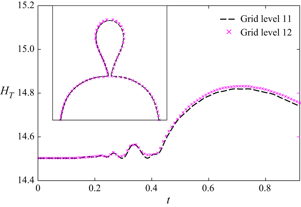
We adopt both gradient-based and curvature-based adaptive mesh refinement (AMR), similar to that used in the recent article of Behera & Chakraborty (Reference Behera and Chakraborty2022), to discretize the domain in an effort to minimize the computational cost significantly. The gradient-based AMR is used to compute the volume fraction. At the fluid–fluid interface, the mesh is refined up to level 11 (211 cells along the domain width), and the far-field refinement level 6 (26 cells along the domain width) is used. Tripathi, Sahu & Govindarajan (Reference Tripathi, Sahu and Govindarajan2015) previously obtained approximate results for complex drop shapes using a similar mesh structure. As the present phenomenon encounters high curvatures during bridge formation, later at the moment of pinch-off and entrapment of outer fluid globules, the mesh is again refined to level 12 at the concerned regions using curvature-based AMR. These special considerations of dynamic interfacial meshing are decisive towards capturing the dynamically evolving complex topology in accordance with the focal theme of investigation of this work, which is otherwise known to be a challenge for the computational methods that do not intrinsically consider assured interfacial resolution over scales compatible with the morphological features of the artificially smeared interface. The above numerical scheme is benchmarked by comparing the present results with previously established experimental and numerical results prior to investigating the present problem statement (refer to § 3.1 for detailed discussion). The grid convergence test is also performed, which is provided in Appendix A for convenience. It is worth mentioning that for all the computational results presented herein, the drops are initially separated by a maximum of one or two simulation cells for rapid film drainage.
3.1. Validation of numerical method
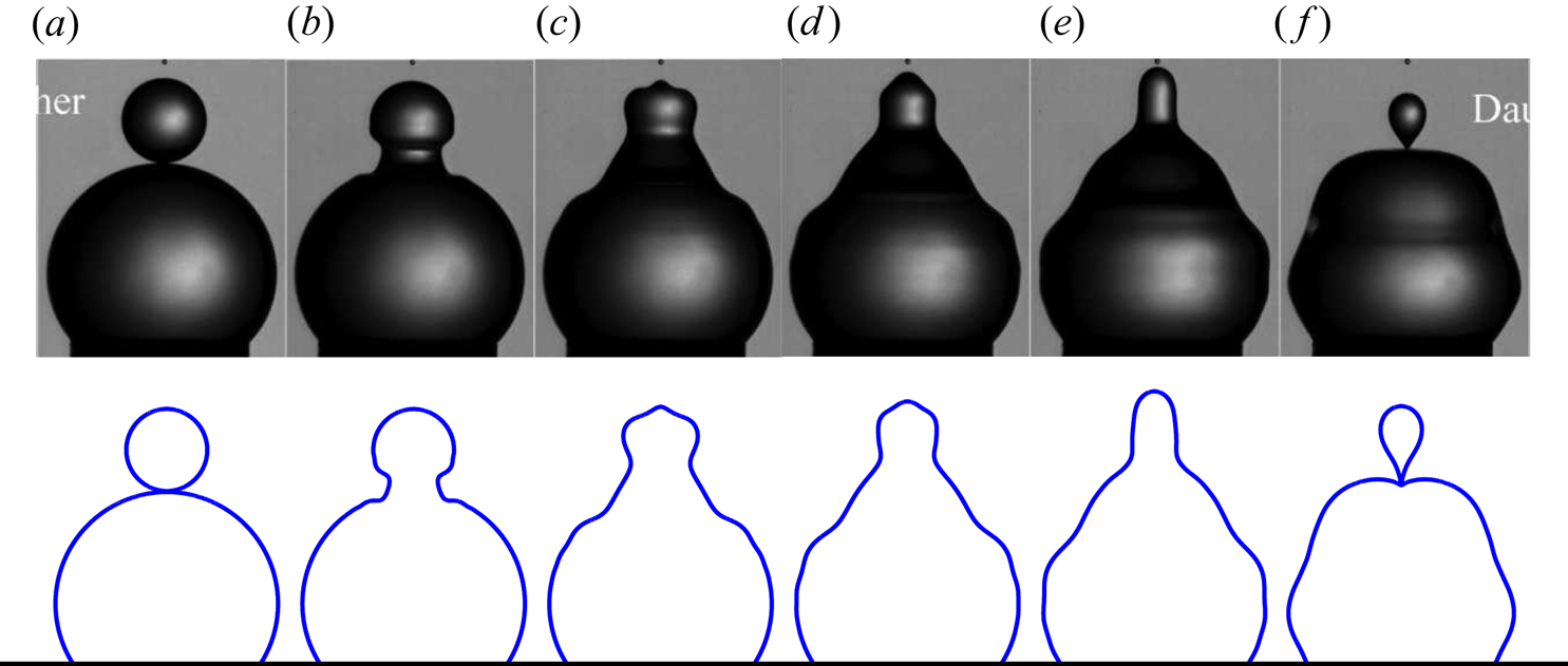
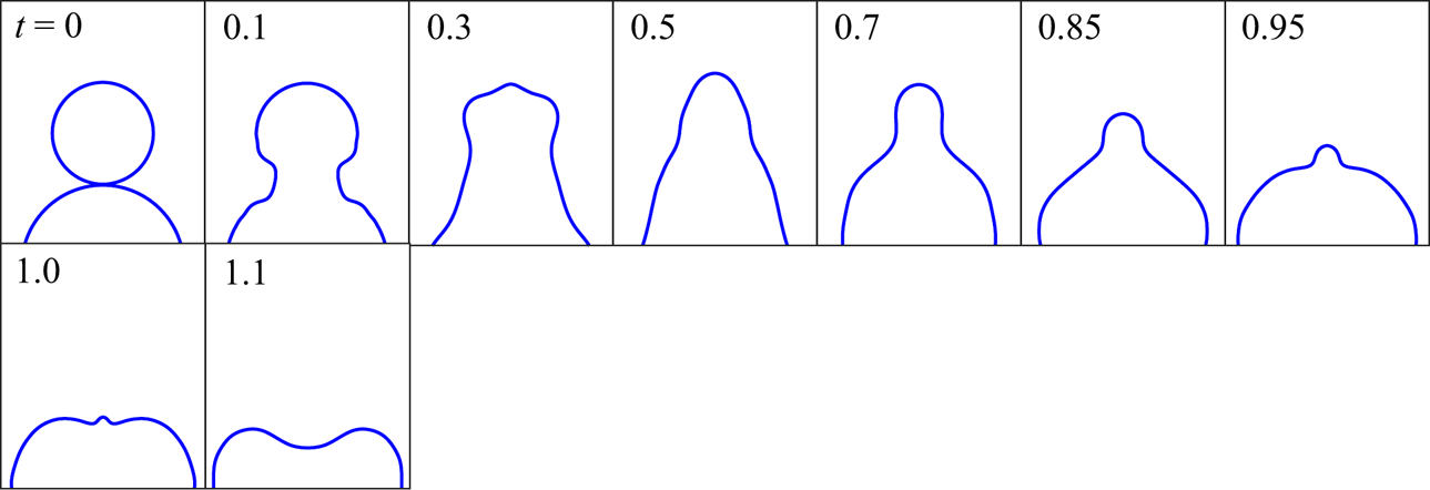
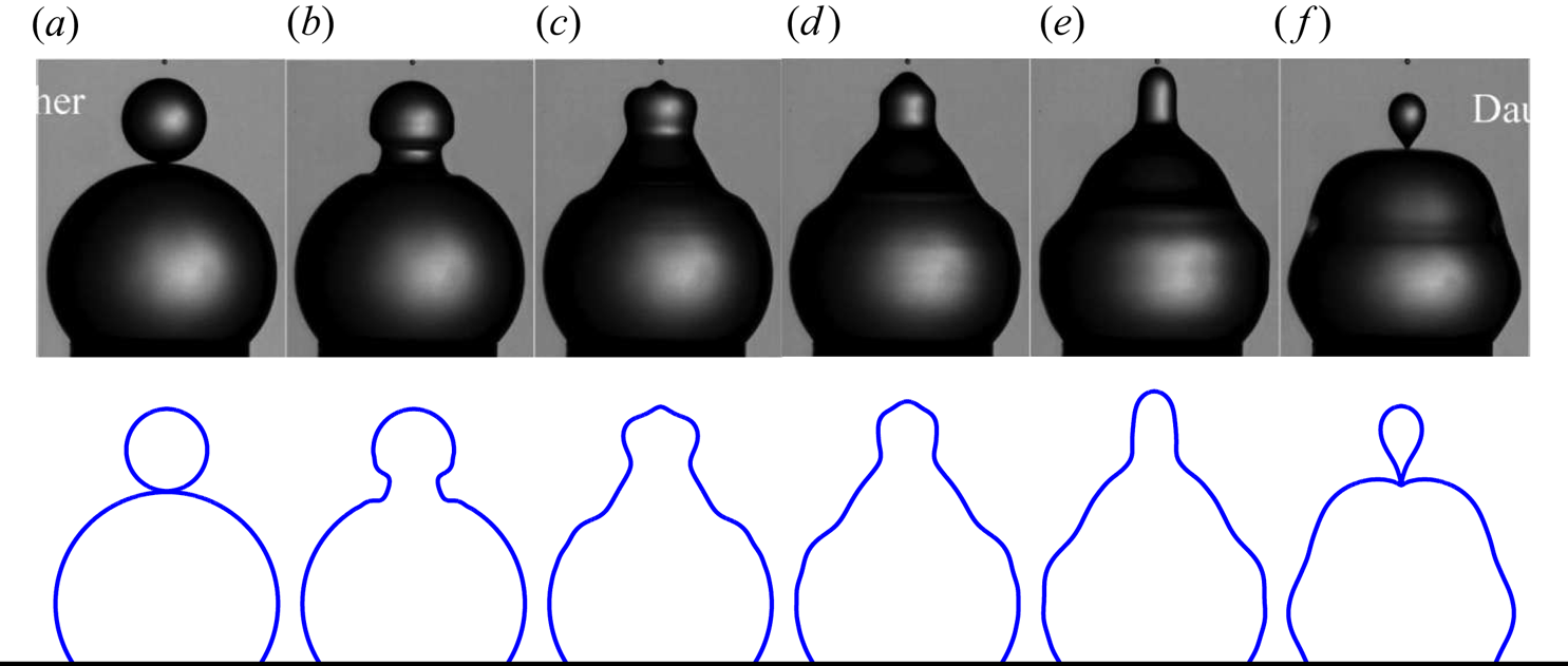
In figure 2, we compare our simulated coalescence events with the reported experimental results of Zhang et al. (Reference Zhang, Li and Thoroddsen2009). In their experiments, two vertically aligned water drops with parent ratio  $\beta = {\bar{D}_f}/{\bar{D}_m} = 2.72$ are allowed to collide in an air medium in the absence of external field (CaE = 0) with a negligible approaching velocity. From their given data, the dimensionless parameters are obtained as Ohi = 0.0058, Ohe = 0.00011, Bo = 0.092 and A = 0.997. By comparing the drop contours at different times, it is confirmed that our numerical model predicts the progress of coalescence and pinch-off phenomena very well. The accuracy of the present numerical method is further examined by comparing the size of the daughter drop. From the present study, the diameter of the daughter droplet (or the generated droplet) is found to be
 ${\approx} 0.52{\bar{D}_m}$ which is approximately the same as the experimentally reported value of
 $0.48{\bar{D}_m}$. Note that Zhang et al. (Reference Zhang, Li and Thoroddsen2009), in their experiments, considered one supported drop (the bottom one) on a nozzle. The upper drop (the smaller one) was allowed to fall on it from a glass needle, for studying the satellite-drop formation in the coalescence event. They observed that pinch-off typically occurred much before the capillary wave propagation could reach the bottom nozzle. Thus, the presence of the bottom nozzle was inconsequential towards dictating the coalescence dynamics. Hence, two freely suspended drops in air could alternatively replicate the physical features of their experiments as well, as evidenced from figure 2.
Advancement of coalescence of water droplets with time for β = 2.72, CaE = 0, Bo = 0.092, Ohi = 0.0058, Ohe = 0.00011 and A = 0.997. The upper panel shows the experimental results of Zhang et al. (Reference Zhang, Li and Thoroddsen2009) and the lower panel represents the present numerical results. The snapshots are taken at dimensional time (a) 0 ms, (b) 0.27 ms, (c) 0.67 ms, (d) 0.93 ms, (e) 1.2 ms and (f) 1.8 ms.
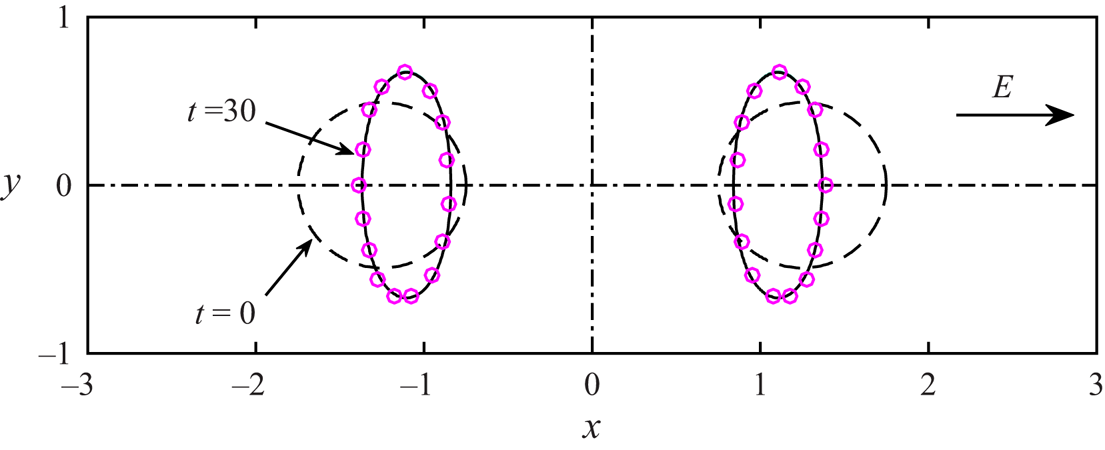
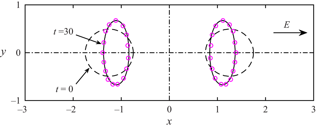
In an effort to establish the efficacy of our numerical approach in the scenarios where EHD interactions are present as well, we next present the interaction between two neutrally buoyant (Bo = 0 and A = 0) equal-sized drops in a uniform electric field, as shown in figure 3. In this study, the present results are compared with a reported numerical model of Baygents et al. (Reference Baygents, Rivette and Stone1998), where the parameters used for simulation were R = 2, S = 8, λ = 1 and  $C{a_E} = 2$. They adhered to the Stokes flow limit by taking the Reynolds number
 $Re( = {\bar{\rho }_e}\bar{D}_m^2{\bar{\varepsilon }_e}\bar{E}_0^2/\bar{\mu }_e^2) \ll 1$. Since
 $O{h_e} = \sqrt {C{a_E}/Re}$, the representative choices of
 $C{a_E} = 2$ and Re = 0.125 yielded Ohe = 4, conforming to the domain of applicability of our framework. From figure 3, it is evident that the numerically obtained shape and motion of the drop couple, as obtained from the present study, agree well with the previous findings of Baygents et al. (Reference Baygents, Rivette and Stone1998).
Interaction of two equal-sized droplets in uniform electric field for CaE = 2, Ohi = Ohe = 4, Bo = 0 and A = 0. The solid lines represent the numerical results of Baygents et al. (Reference Baygents, Rivette and Stone1998) and the circles represent our numerical results.
4. The physics of topological bifurcations
4.1. Dynamical evolution without electric field
One of the primary hydrodynamic features, even without the action of an electric field, is the realm of two-drop interaction in the presence of fluid flow, which turns out to be significantly more involved as compared with the corresponding single-drop dynamics. On first physical contact as a prelude to possible coalescence, a liquid bridge connecting the two drops (herein termed as the ‘neck’) is formed. The interfacial tension tries to minimize the contact area during this course, so that the neck gradually widens. This results in liquid motion from the mother drop towards the father drop. At the onset of merging of the two drops, the curvature of the neck remains very high. As the neck attempts to expand, it generates a strong capillary wave, which during its propagation towards the ends of the drops, brings in shape distortions of the same, as shown in figure 2. Because of the size disparity between the parent drops (the mother drop is considered to be much smaller than the father drop), the capillary wave converges at the apex of the mother drop quite early, inducing a vertically upward capillary pull. This force is essentially a function of the initial neck curvature, which in turn is a function of the parent ratio, β (Deka et al. Reference Deka, Biswas, Chakraborty and Dalal2019). Increase in the neck curvature intensifies the capillary wave, strengthening the upward capillary pull that results in longer protrusions at the apex. The upward capillary pull, however, is resisted by the viscous effects and gravity.
For high Oh (referring to systems where either drop viscosity or outer fluid viscosity is high), the loss in capillary wave energy through viscous dissipation may be substantial (Blanchette & Bigioni Reference Blanchette and Bigioni2006). Thus, only a small fraction of the capillary momentum may be available at the top, weakening the net upward pull to an extent to preclude pinch-off. The gravitational force, which acts in the downward direction, is directly proportional to the specific weight of the fluid. For high Bo, thus, the capillary pull may not be strong enough to carry the fluid to a substantial height. In this case, vertical collapse may occur as against pinch-off. However, if the capillary-wave-induced upward pull overcomes the viscous- and the gravity-induced resistances, a cylindrical protrusion forms at the apex, as shown in figure 2(e). After achieving a threshold height, when the curvature at the peak of the cylindrical structure becomes sufficiently large, the same results in vertical downward pull (or vertical collapse) at the apex and a concomitant horizontal inward pull (or horizontal collapse) at the neck. Hydrodynamically driven pinch-off, thus, may emerge to be a competing consequence between the vertical and the horizontal collapse. If the vertical collapse prevails, pinch-off does not occur and vice versa (Blanchette & Bigioni Reference Blanchette and Bigioni2006).
4.2. Effect of electric field
Subjected to an electric field, instant charging of the drops occurs owing to the discontinuity in the relevant electrical properties at the interface. For R/S > 1, the upper face of a drop holds positive charge, whereas the lower face holds negative charge. A reverse charge distribution pattern can be observed for R/S < 1 (Salipante & Vlahovska Reference Salipante and Vlahovska2010; Mandal et al. Reference Mandal, Sinha, Bandopadhyay and Chakraborty2018). These distinctive scenarios, accordingly, alter the electrical stresses to an extent that results in concomitant variations in the viscous and the capillary stresses, so as to realize a dynamic force balance at the interface. Thus, the contrast in the relevant electro-physical properties plays the most non-intuitive role in altering the dynamic force balance and orchestrating topological alterations under electrical forcing.
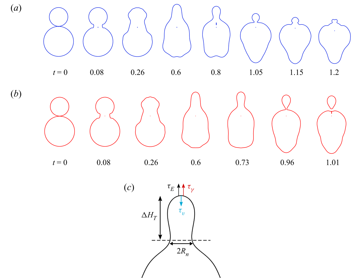
To highlight some key distinctive features of drop–drop coalescence with and without electric fields, we portray the drop contour evolution for CaE = 0 and CaE = 0.1 in figure 4(a) and 4(b), respectively, considering parent ratio β = 1.6, electro-physical parameters (R, S) = (10, 2.3) and drop-side Ohnesorge number Ohi = 0.005. In order to physically relate the above with an experimentally realizable system, we consider silicone oil ( ${\bar{\rho }_i}\sim 920\ \textrm{kg}\ {\textrm{m}^{ - 3}}$,
 ${\bar{\mu }_i}/{\bar{\rho }_i}\sim 1\ \textrm{cSt}$,
 ${\bar{\varepsilon }_e}\sim 2.3{\varepsilon _0}$) as the drop phase and air as the carrier phase with a surface tension value γ ~ 20 mN m−1 (Ricci, Sangiorgi & Passerone Reference Ricci, Sangiorgi and Passerone1986). The conductivity of the air typically varies between
 $O({10^{ - 15}})$ and
 $O({10^{ - 14}})\ \textrm{S}\ {\textrm{m}^{ - 1}}$ (Kamsali, Prasad & Datta Reference Kamsali, Prasad and Datta2009), whereas that of the silicone oil varies between
 $O({10^{ - 13}})$ and
 $O({10^{ - 11}})\ \textrm{S}\ {\textrm{m}^{ - 1}}$ (Mhatre, Deshmukh & Thaokar Reference Mhatre, Deshmukh and Thaokar2015a; Abbasi et al. Reference Abbasi, Song, Kim and Lee2019). For such property ranges, the charge relaxation time scale may be comparable to the droplet coalescence time scale. However, in reported benchmark experiments, the conductivity of the silicone oil could be significantly enhanced (up to ~10−6 S m−1) by using specific doping techniques (Yin & Zhao Reference Yin and Zhao2002), manifesting its leaky dielectric feature. Thus, for the silicone oil–air system, a wide range of conductivity ratios (R) can be realized in practice, covering both perfect dielectric and leaky dielectric behaviour. However, following a rich tradition of prior works (Ha & Yang Reference Ha and Yang2000; Lac & Homsy Reference Lac and Homsy2007; Mählmann & Papageorgiou Reference Mählmann and Papageorgiou2009; Poddar et al. Reference Poddar, Mandal, Bandopadhyay and Chakraborty2018), we considered R ~ O(10) for our reported results We have verified that while higher orders of magnitude of R indeed alter the quantitative results, the nature of physical forcing remains unaltered for the entire physically plausible regime of the pertinent electrical properties. The values of the Bond number, Atwood number and outer-side Ohnesorge number are taken as Bo = 0.32, A = 0.998 and Ohe = 0.0002 (obtained for drop diameter of 0.8 mm), respectively, throughout this work, unless mentioned otherwise.
Coalescence outcomes for (a) CaE = 0 and (b) CaE = 0.1. The other parameters considered are β = 1.6, R = 10, S = 2.3, Ohi = 0.005, Ohe = 0.0002, Bo = 0.32 and A = 0.998. (c) Schematic describing key forces acting at the top and the geometrical features during capillary pulling.
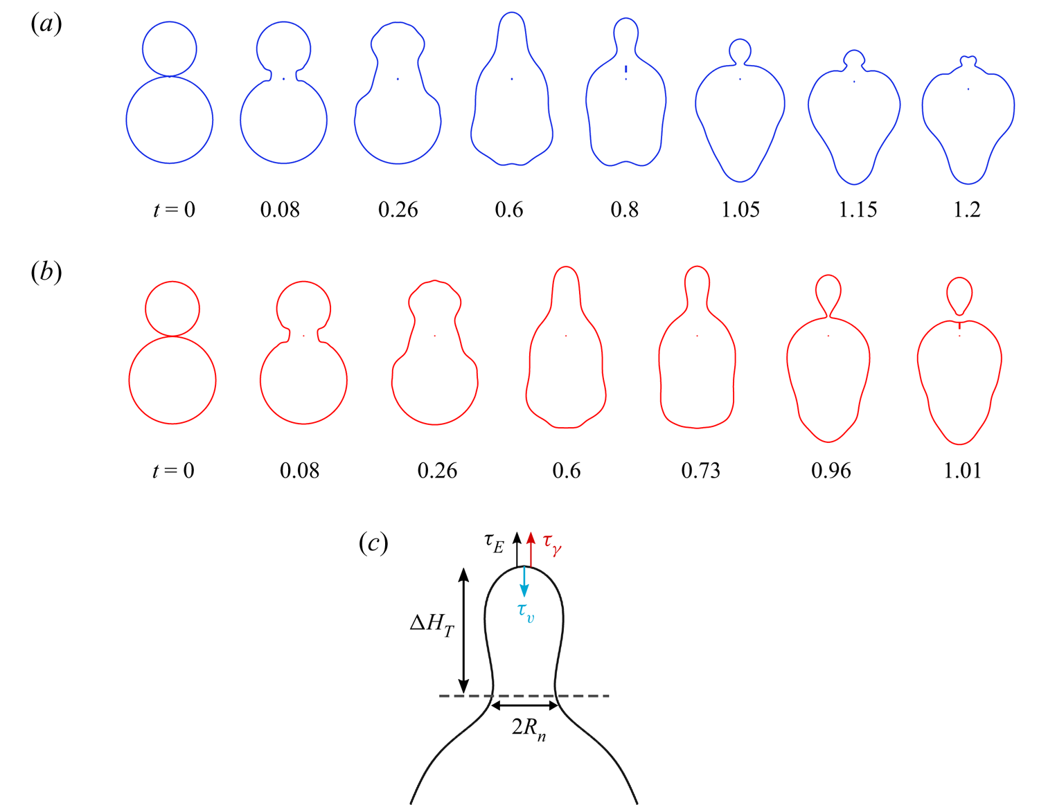
As shown in figure 4, the drop deformations for CaE = 0 and CaE = 0.1 are almost similar up to t = 0.6. However, at t = 0.8 the drop shape for CaE = 0.1 appears to be clearly more stretched. Eventually, significant topological variations start to occur, leading to pinching of the daughter drop, whereas for CaE = 0, no such phenomenon is observed over the same parametric space. Figure 4(c) shows the schematic representation of various forces acting on the drop apex that dictates topological variation during electric-field-mediated coalescence; the importance of these forces is discussed elaborately in Appendix B.
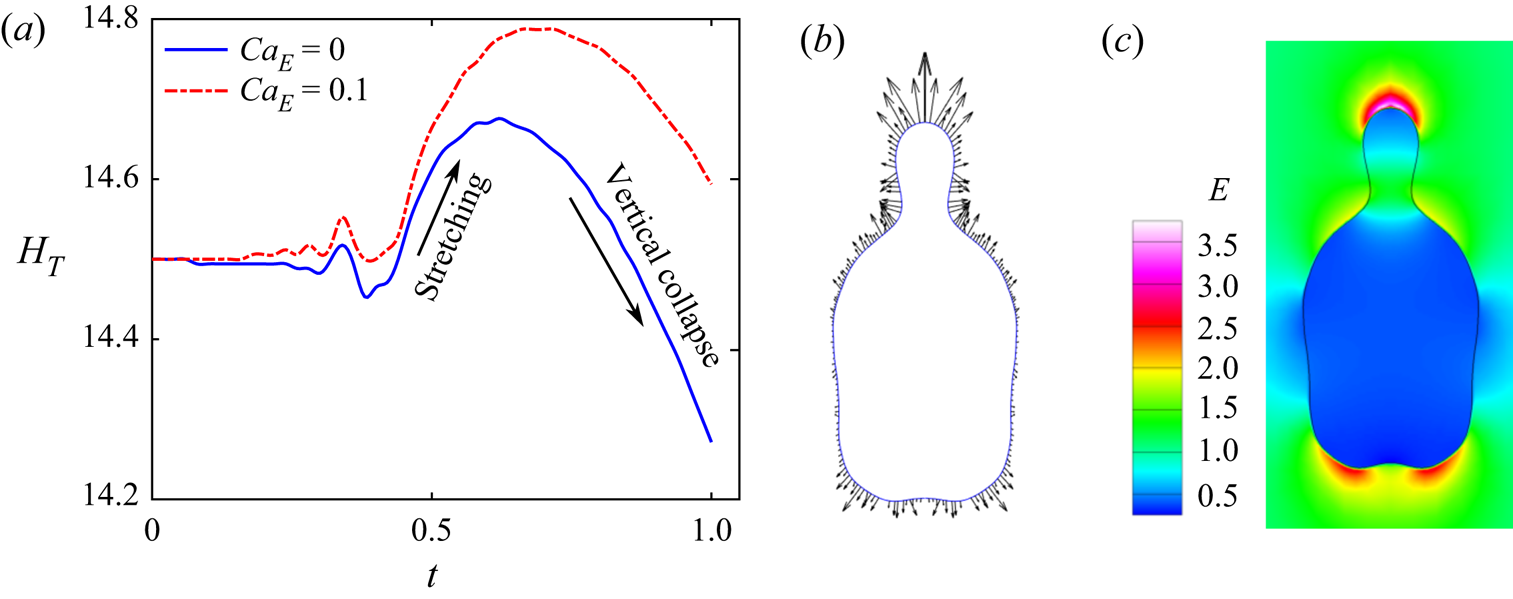
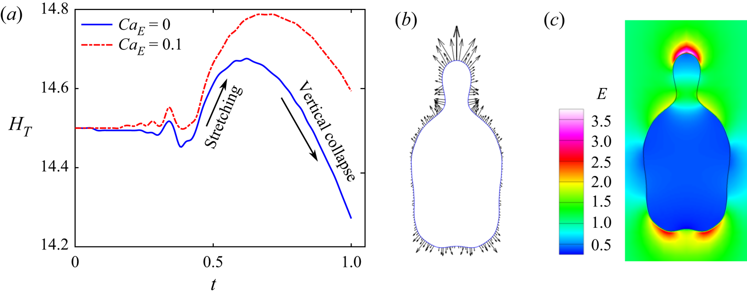
The role of electric field in triggering a bifurcation to the pinch-off behaviour can be best explained by analysing the vertical deformation of the drop with time. Figure 5(a) depicts the transient variation in the apex position of the mother drop (HT) in the computational domain for CaE = 0 and 0.1, from which it can be observed that the variations due to electric field are not significant until t = 0.5. However, beyond this temporal limit, HT increases dramatically for CaE = 0.1, resulting in the appearance of a significantly longer protrusion at t = 0.8. This delays the subsequent vertical collapse, leading to pinch-off.
(a) Variation of drop apex position HT with time. (b) Demonstration of electric force acting on drop and (c) electric field profile at t = 0.84. The parameters considered are β = 1.6, R = 10, S = 2.3, Ohi = 0.005, Ohe = 0.0002, Bo = 0.32 and A = 0.998.
The bifurcation from vertical collapse to pinch-off may be addressed from a mechanistic point of view, by considering the geometrical space at top occupied by the northern half of a polarized drop having originally a spherical shape. The jump  $([{\cdot} ])$ in the normal component of the electric traction at the interface of the said entity can be derived as
 \begin{equation}\boldsymbol{n}\boldsymbol{\cdot }[{\boldsymbol{\tau }_M}\boldsymbol{\cdot }\boldsymbol{n}] = \frac{{{q_S}({E_{n,i}} + {E_{n,e}})}}{2} - \frac{{(1 - S)}}{2}({E_{n,i}}{E_{n,e}} - E_{t,i}^2),\end{equation}
where  ${q_S}$
 $( = {E_{n,e}} - S{E_{n,i}})$ is the surface charge density (Saville Reference Saville1997) and En and Et are the normal and tangential electric field components, respectively. The first term on the right-hand side of (4.1) is the stress due to Coulombic force (
 ${\tau _{coulomb}}$, generated due to interaction between surface charge and electric field) and the second term is the stress generated due to dielectrophoretic force (
 ${\tau _{diel}}$, generated due to jump in electrical permittivity at the interface). By appealing to the expressions of the electric and the velocity field calculated by using Taylor's leaky-dielectric model (Reference Taylor1966) for the individual drops, the order of magnitude of the respective normalized stress components may be estimated as
 ${\bar{\tau }_{coulomb}}/(\gamma /{\bar{D}_m})\sim C{a_E}(9/2)(R - S)(R + 1)/{(R + 2)^2}$ and
 ${\bar{\tau }_{diel}}/(\gamma /{\bar{D}_m})\sim C{a_E}(9/2)R(S - 1)/{(R + 2)^2}$. Note that the Coulombic stress vanishes for R = S, which is the condition for a perfectly dielectric fluid system having zero net charge (Mandal, Bandopadhyay & Chakraborty Reference Mandal, Bandopadhyay and Chakraborty2016a). Similarly, the dielectrophoretic stress vanishes when there is no permittivity jump across the phases, i.e. S = 1.
The electric stress induces flow in the drop vicinity, the jump in which induces hydrodynamic stress at the interface  $({\tau _{EHD}})$, where
 ${\bar{\tau }_{EHD}}/(\gamma /{\bar{D}_m})\sim ({\textstyle{9 \over 5}})C{a_E}((R - S)(3\lambda + 2)/{(R + 2)^2}(\lambda + 1))$. Thus, the total electrically induced stress created at the apex, in its normalized form, scales as
 \begin{align}
{\tau _E} & = \dfrac{{{{\bar{\tau }}_{coulomb}} +
{{\bar{\tau }}_{diel}} + {{\bar{\tau }}_{EHD}}}}{{(\gamma
/{{\bar{D}}_m})}}\sim C{a_E}\left\{\begin{array}{@{}c@{}}
{\underbrace{{\dfrac{9}{2}\dfrac{{({R^2} - S)}}{{{{(R +
2)}^2}}}}}_{{\textrm{due}\ \textrm{to}\ \textrm{electric}\
\textrm{force}}} + \underbrace{{\dfrac{9}{5}\dfrac{{(2 +
3\lambda )(R - S)}}{{(1 + \lambda ){{(R +
2)}^2}}}}}_{{\textrm{due}\ \textrm{to}\ \textrm{EHD}\
\textrm{flow}}}}\end{array} \right\}\nonumber \\
& = \dfrac{9}{{10}}C{a_E}\dfrac{{(5{R^2}(\lambda + 1) +
2R(3\lambda + 2) - S(11\lambda + 9))}}{{(\lambda + 1){{(R +
2)}^2}}}.
\end{align}
While the gravitational force and capillary pull always attempt to pull the apex downwards and upwards, respectively (the corresponding normalized stresses respectively read as  ${\bar{\tau }_g}/(\gamma /{\bar{D}_m})\sim Bo{H_T}R_n^2$ and
 ${\bar{\tau }_\gamma }/(\gamma /{\bar{D}_m})\sim 1/{R_n}$, where Rn is the dimensionless instantaneous neck radius as shown schematically in figure 4c), the electrically induced traction at the top can preferentially act either upwards or downwards, depending on the specific values of (R, S). Additionally, (4.2) suggests that there exists a critical characteristic demarcating boundary line in the (R, S) phase space, along which the net electric forcing effect turns out to be zero, recovering the hydrodynamically manipulative limit. The equation of this critical characteristic line is found as
 \begin{equation}S = R(5R\lambda + 5R + 6\lambda + 4)/(11\lambda + 9).\end{equation}
For the property combination values cited herein, i.e. (R, S) = (10, 2.3), the electric stress pulls the mother drop in the upward direction as suggested by the volumetric electric force  $({\boldsymbol{F}_E})$ profile presented in figure 5(b) as well as the theoretically obtained sign of
 ${\tau _E}$ from (4.2). As the capillary pull gradually stretches the mother drop, the charges are pushed towards the apex region. With the continuation of vertical stretching, the lateral width of the protrusion gradually decreases, thereby decreasing the local surface area at the apex. Thus, the surface charge density
 ${q_S}$ becomes locally high. Since
 ${q_S}\boldsymbol{= }({\boldsymbol{E}_e} - S{\boldsymbol{E}_i})\boldsymbol{\cdot }\boldsymbol{n}$, increase in the charge density amplifies the jump in the normal component of the electric field across the interface, which results in a significantly high localized electric field distribution at the top surface as compared with the bottom, as shown in figure 5(c). Consequently, the electric force
 $({\boldsymbol{F}_E} \propto {E^2})$ becomes large at the top (as shown in figure 5b) and, thus, produces strong upward stretching, aiding the capillary pull. Their cooperative interplay, as further orchestrated by the simultaneous alteration in CaE and β, can result in decisive dynamical bifurcations over preferential parametric spaces, as discussed in the subsequent sections.
5. Influence of the key governing parameters
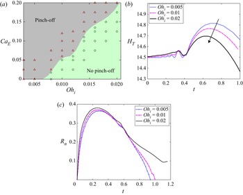
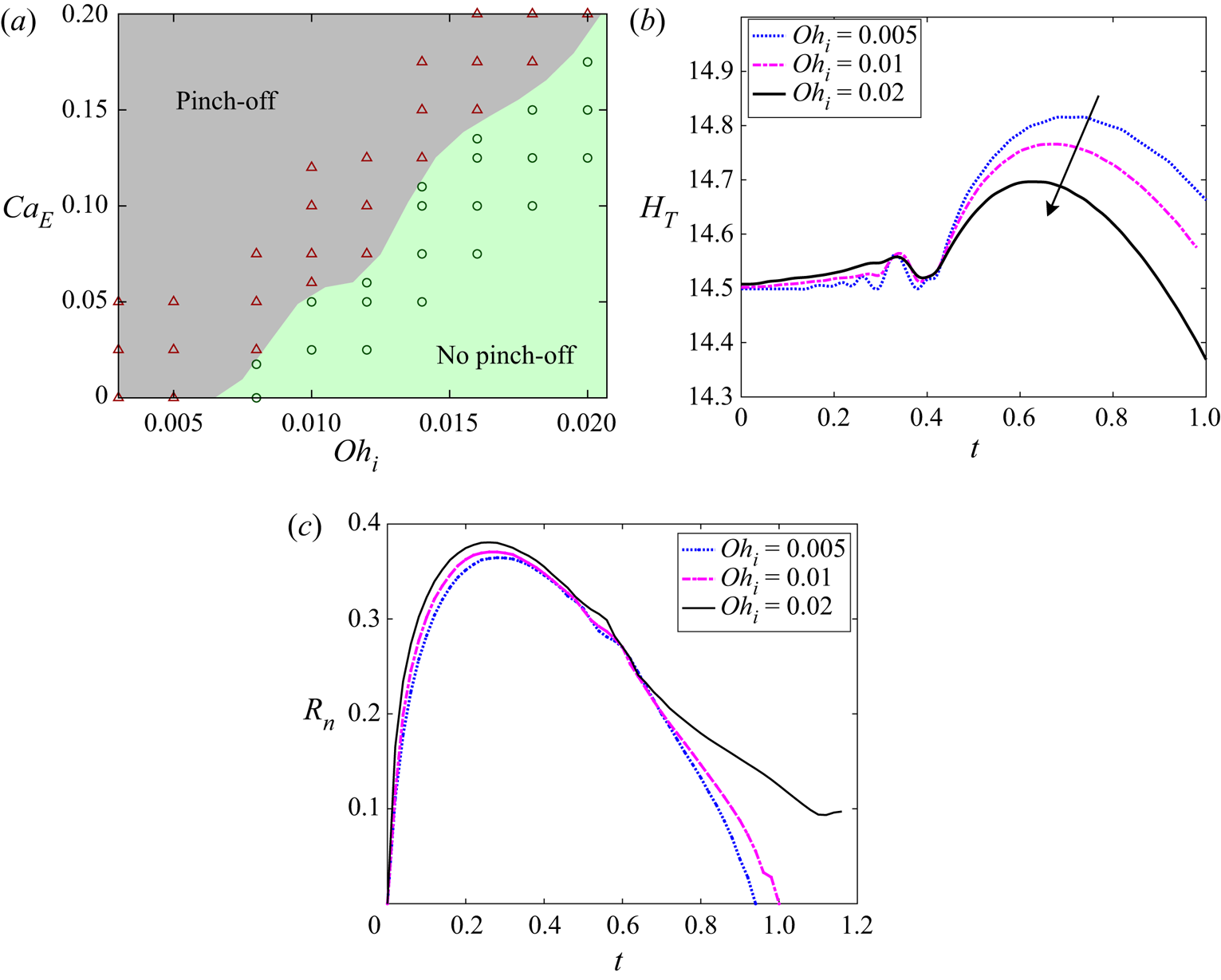
Since the capillary-driven interfacial motion and deformation are influenced by the electric and viscous forces, pinch-off may be effectively governed by the parameters CaE and Ohi. In figure 6(a), we have marked the no pinch-off and pinch-off regimes in the  $C{a_E}$–
 $O{h_i}$ parametric space for R = 10, S = 2.3 and β = 2. As can be noted, high CaE creates a favourable condition for pinch-off, whereas high Ohi creates an adverse condition. Accordingly, with the increase in Ohi, the critical (or minimum) value of CaE required for pinch-off increases. To obtain a physical insight into the same, the effect of Ohi on the vertical deformation is depicted in figure 6(b) for CaE = 0.1 and β = 2. For large Ohnesorge number, the fraction of capillary energy lost through viscous dissipation is more, as discussed earlier in § 4.1. Thus, the upward stretching induced by the combined EHD–capillary pull is arrested, resulting in early vertical collapse. Moreover, the increase in Ohi increases the local neck radius Rn, as illustrated in figure 6(c). As a result, the pressure difference between the bridge and the father drop, i.e.
 $\Delta p = {p_{neck}} - {p_{father}} \approx 1/ R_n - 1/ H_n - 1/ \beta$, decreases (where Hn is the axial length of the neck). This fall in the neck pressure deaccelerates the neck-to-bulk flow drainage, resisting the horizontal collapse. Consequently, while pinch-off is obtained for Ohi = 0.005 and 0.1, for Ohi = 0.02 the neck gradually starts to widen after certain initial thinning. The viscous resistance can be overcome by enhancing the upward pull, which can be achieved by increasing the CaE value, as demonstrated in figure 5(a).
(a) Pinch-off and no pinch-off regimes in  $C{a_E}$–
 $O{h_i}$ space for β = 2. Effect of drop-side Ohnesorge number Ohi on the transient variation in (b) drop apex HT and (c) neck radius Rn for CaE = 0.1 and β = 2. The other parameters considered are R = 10, S = 2.3, Ohe = 0.0002, Bo = 0.32 and A = 0.998.
In a purely hydrodynamic approach of overcoming the viscous resistance, maintaining a parent ratio (β) higher than a threshold value is imperative (Zhang et al. Reference Zhang, Li and Thoroddsen2009; Deka et al. Reference Deka, Biswas, Chakraborty and Dalal2019). This is attributed to the fact that the strength of the capillary pull depends on the initial local curvature at the contact region (or neck), and thus depends on the diameter ratio as described before in § 4.1. Increase in diameter ratio or equivalently increase in the size of the father drop results in an increase in the neck curvature, as attributed to the higher flatness of the father drop surface near the contact region and vice versa. Thus, there exists a critical diameter ratio, below which the capillary wave may be weak enough to induce sufficient upward stretching, resulting in early commencement of the vertical collapse to an extent that pinch-off may not occur. In the absence of external forces, and for weak gravitational forces ( $Bo \ll 1$, i.e. when density difference is small), such a critical parent ratio (βc) is typically a function of the Ohnesorge number only.
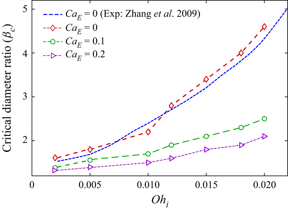
By offering an additional albeit inter-connected degree of freedom, here we show that CaE can also be a major controlling parameter for βc, under electric-field-mediated interactions. To identify the critical parent ratio under electric forcing for the previous system, we perform simulations for different sets of (Ohi, CaE) by progressively varying the value of β, as collated in figure 7. For all the values of CaE, βc is seen to rise monotonically with an increase in Ohi. Note that in the absence of electric field (i.e. for CaE = 0), our numerical results agree well with the experimental findings of Zhang et al. (Reference Zhang, Li and Thoroddsen2009), delineating an increase in βc with increasing Ohi.
Effect of drop-side Ohnesorge number Ohi on critical diameter ratio βc for different CaE. Other parameters considered are R = 10, S = 2.3, Ohe = 0.0002, Bo = 0.32 and A = 0.998.
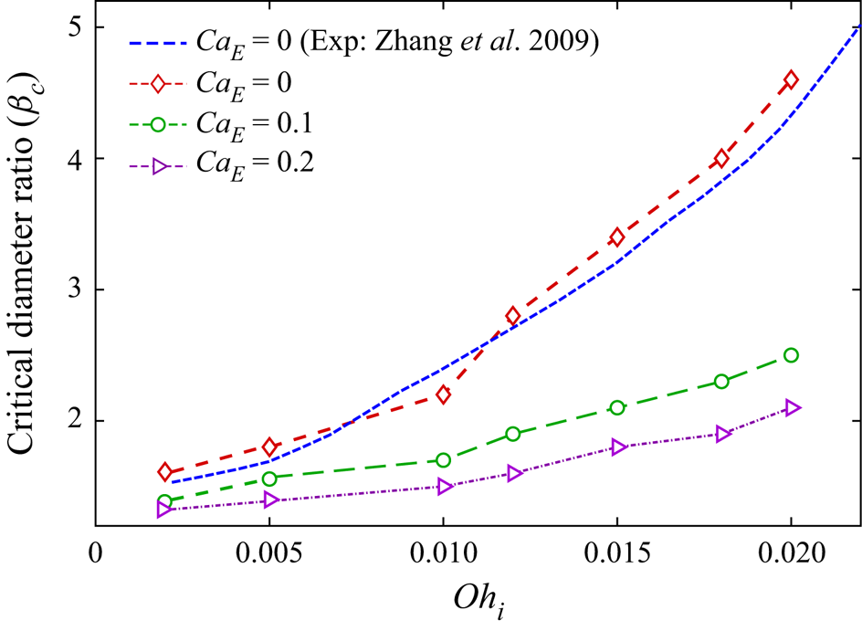
Two additional phenomena further feature under electric forcing. First, βc significantly deviates towards a lower value. This is because of the fact that the coupled EHD–capillary pull yields a much stronger upward stretching than for the capillary pull alone, as shown earlier in figure 5(a). This obviates the need for a higher parent ratio as inevitable for a pure hydrodynamic scenario. Second, the dependence of βc on Ohi becomes much less consequential. For example, in the case of CaE = 0, βc varies from 1.55 to 4.6 (almost 2.9 times) on varying Ohi from 0.002 to 0.02, whereas the same variation in Ohi leads to an increase in βc from 1.3 to 2.1 (almost 1.6 times) for CaE = 0.2. Using a power-law curve-fitting model, we found that βc varies with  $Oh_i^{1.85}$ for CaE = 0, whereas for CaE = 0.1 and 0.2, βc varies with
 $Oh_i^{1.48}$ and
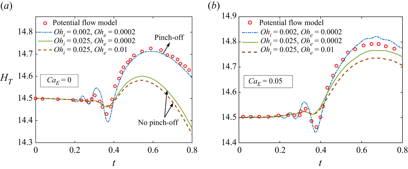
 $Oh_i^{1.34}$, respectively. It is worth mentioning that in the reported experimental studies, albeit without involving electric-field-mediated effects, the lowest possible value of βc reported was 1.55 (Zhang et al. Reference Zhang, Li and Thoroddsen2009), whereas the same is found to be 1.3 in the present study, for CaE = 0.2 and Ohi = 0.002. For β < 1.3, we observe stretching of the father drop owing to the convergence of capillary wave at the tip of the same (the bottommost position), which prevents pinch-off. As is evident, the viscous effects may still significantly influence the coalescence outcomes despite delving into the intertio-capillary regime; hence, the potential (or inviscid) flow models (Garzon et al. Reference Garzon, Gray and Sethian2018) may not turn out to be adequate in predicting the various morphological events with the envisaged quantitative accuracy. A concise accounting of this is outlined in Appendix B.
5.1. Pinch-off modes and topology of secondary (or daughter) drop
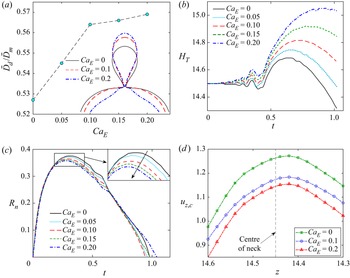
Post-identification of the critical limit of parent ratio, we probe the effect of the electric field on the daughter drop topology in the pinch-off regime. The electrical properties are kept unchanged in the current section, i.e. R = 10 and S = 2.3, for consistency in the discussion. Figure 8(a) illustrates the variation of daughter drop size (Dd) with CaE for Ohi = 0.005 and β = 2. The drop contours for different CaE are compared at the onset of pinch-off for better physical understanding. The size of the daughter drop shows an increasing trend with increasing CaE. However, the increments are only prominent at the initial rise in CaE. Beyond a certain  $C{a_E}$
 $({\approx} 0.1)$, negligible variations are observed.
Effect of electric capillary number CaE on (a) daughter drop size, (b) transient variation in drop apex HT, (c) transient variation in neck radius Rn and (d) centreline velocity uz,c around the neck at t = 0.7. The parameters considered are β = 2, R = 10, S = 2.3, Ohi = 0.005, Ohe = 0.0002, Bo = 0.32 and A = 0.998.
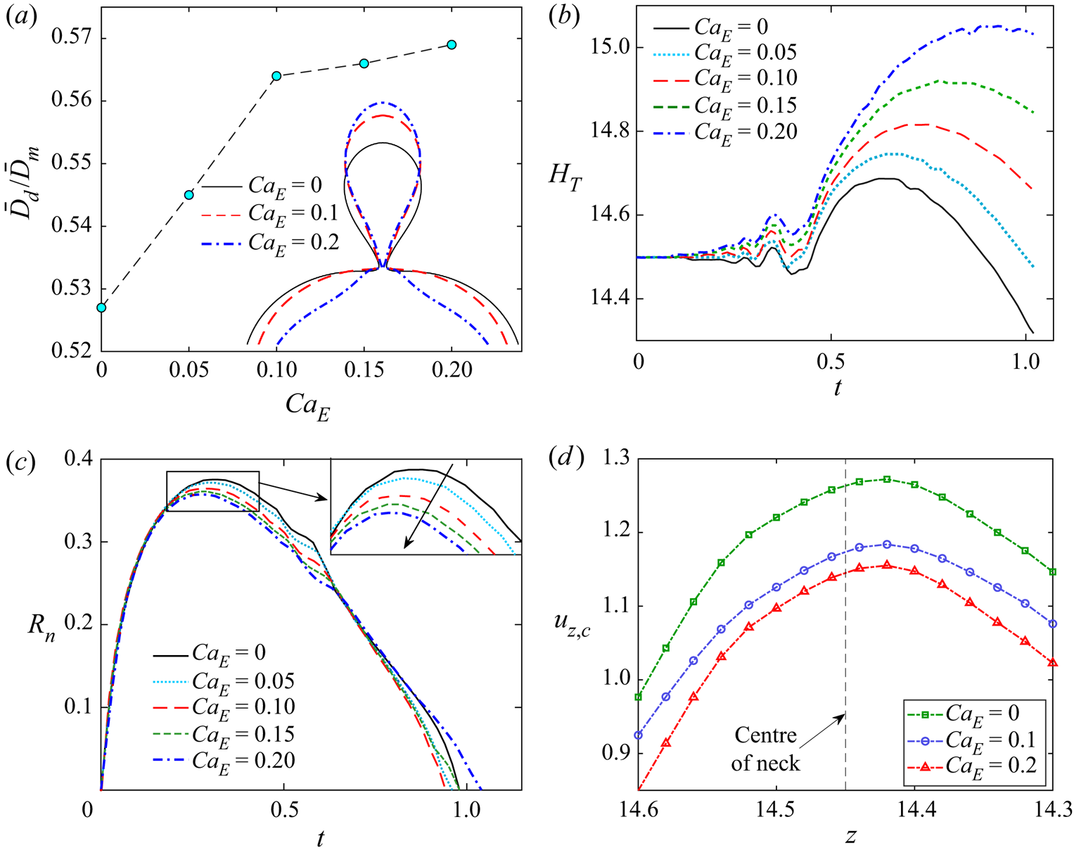
We further analyse the transients in the drop apex position and neck radius for different CaE values in figures 8(b) and 8(c), respectively. In the HT versus time characteristics shown in figure 8(b), the continuous rise in HT refers to cylindrical structure formation which has been discussed earlier, whereas the fall in HT corresponds to the vertical collapse phase. At the initial stage, a small increment in HT is observed with the increase in CaE, attributed to the electric-field-induced deformations only (Saville Reference Saville1997; Vlahovska Reference Vlahovska2019). However, after the collapse of the capillary wave at the apex, the coupled effect of EHD–capillary pull comes into play, causing a noticeable increase in the elongation rate. As the deviation in maximum apex position  $(d(H_T^{max})/d(C{a_E}))$ continuously increases with increasing CaE, it signifies that the coupled EHD–capillary pull is much stronger than the linear superposition of individual pulling forces. Looking at the augmented elongation rate, one may argue that the upward stretching directs the flow upwards inside the drop, causing an increase in the volume of the daughter drop. Whereas in reality, the flow always directs towards the downward direction (shown in figure 9), discarding the above possibility. In figure 8(d), on comparing the flow velocities along the centreline (uz,c), we show that for CaE = 0.1, the fluid motion near the neck region is weaker as compared with the case for CaE = 0. As the flow drainage is mainly generated due to the pressure difference between the father drop and the mother drop, the alteration in the fluid velocity must be attributed to this observed finding. Comparing the results at t = 0.55 (during the elongation phase), we observe that on increasing CaE, the pressure at the exit of the neck decreases insignificantly (p = 1.75, 1.66 and 1.58 for CaE = 0, 0.1 and 0.2, respectively). In contrast, at the neck entrance, the pressure falls considerably (p = 5.2, 4.4 and 3.9 for CaE = 0, 0.1 and 0.2, respectively). The small pressure variations in the father drop may be due to its diminutive shape modulation under weaker electric forcing, as shown previously in figure 5(b). The above data show reduction in net pressure difference between neck inlet and outlet, reflected in weaker flow rate. Furthermore, the vertical collapse rate decreases with increasing CaE, as shown in figure 8(b). In conjunction, these phenomena resist the downward flow, causing entrapment of more fluid within the mother drop. Thus, larger daughter drops are produced.
Flow patterns near the upper drop for (a–c) different CaE at t = 0.8. Other parameters considered are β = 2, R = 10, S = 2.3, Ohi = 0.005, Ohe = 0.0002, Bo = 0.32 and A = 0.998.
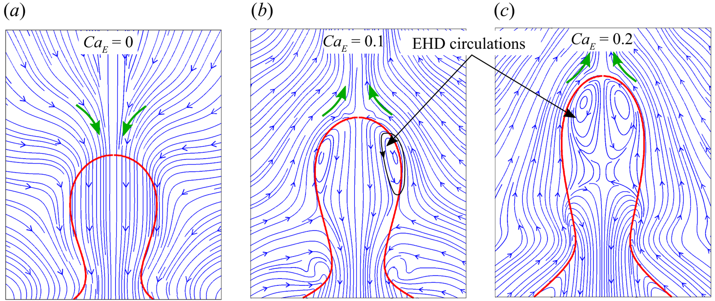
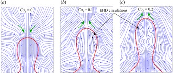
Fundamentally, the normal electric stress is responsible for the above-mentioned variations in drop deformation, while both the tangential and normal electric stress cause alterations in the local flow field (Lac & Homsy Reference Lac and Homsy2007; Esmaeeli & Sharifi Reference Esmaeeli and Sharifi2011; Lanauze, Walker & Khair Reference Lanauze, Walker and Khair2015; Behera & Chakraborty Reference Behera and Chakraborty2020). Figure 9 shows the flow patterns for different CaE at t = 0.8, considering Ohi = 0.005 and β = 2. For CaE = 0, the flow is unidirectional throughout the mother drop, whereas for CaE = 0.1 circulations (or secondary flows) are observed. These circulations emerge to balance the tangential electric stress at the interface. Although an increase in CaE strengthens the circulations, the flow patterns in the neck remain mostly unaffected.
Even though the transient variation in drop apex looks qualitatively similar for all CaE, for CaE = 0.2 the downward displacement of the apex is appreciably small. This suggests that the electric stress, in this case, is comparable to the combined effect of the downward capillary stress and gravitational stress, i.e. τE = τγ + τg, at the onset of the vertical collapse phase. Importantly, increasing CaE from 0 to 0.2 reverses the direction of the outer flow from downward to upward, indicating that for  ${\tau _E} \gg {\tau _\gamma } + {\tau _g}$, non-trivial interfacial deformations are most likely to be produced due to the strong electric pulling and the shearing effect of outer flow (as inferred from the flow patterns shown in figure 9 for
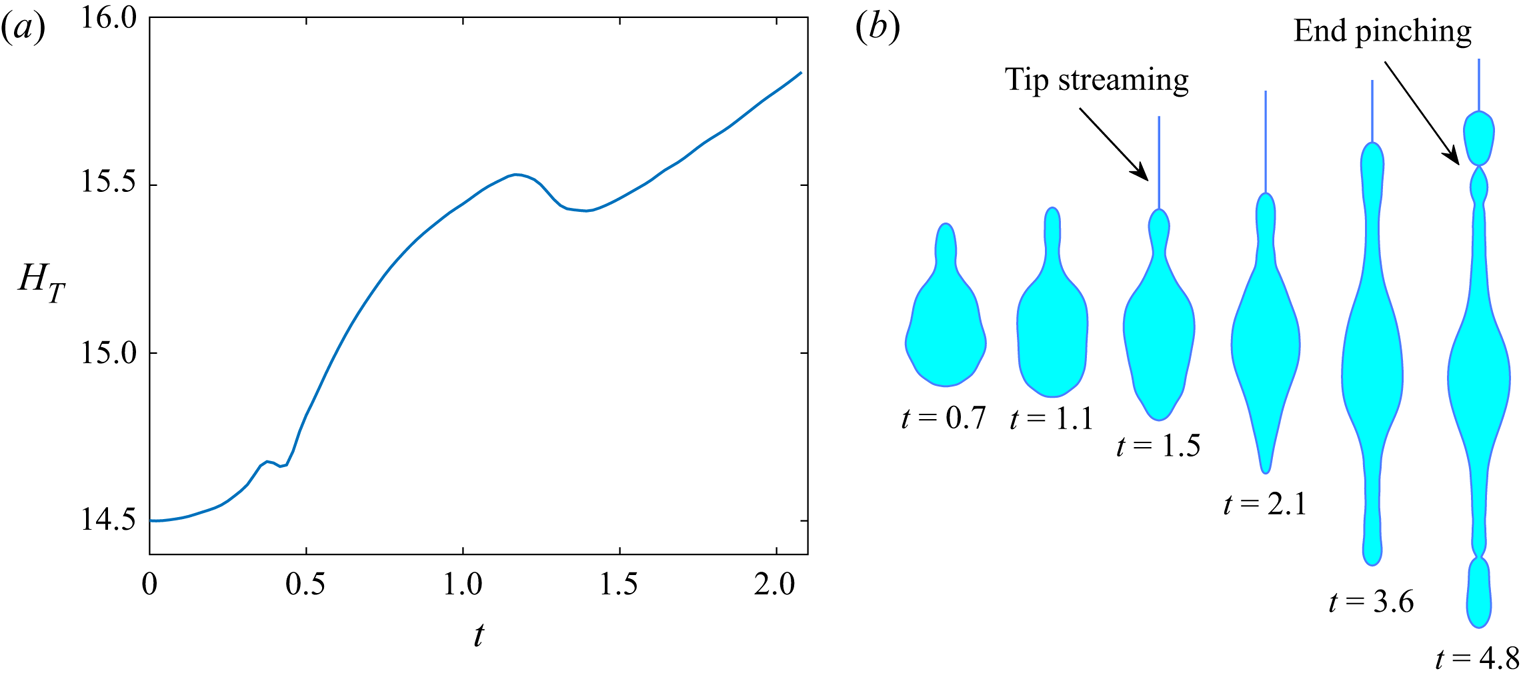
 $Ca_{E} = 0.1$ and 0.2). Accordingly, for CaE = 0.3, the apex rises greatly instead of falling, as demonstrated in figure 10(a). Accordingly, the HT versus t characteristic shown here exhibits a different profile from that shown previously. While for CaE ≤ 0.2 the typical neck collapses are seen to occur around t = 1.1 as shown earlier, the same does not happen for CaE = 0.3, allowing prolonged elongation of the mother drop. At t = 1.2, a thin jet emerges from the mother drop, resulting in tip streaming. Such tip streaming is an electric-field-induced breakup mode reported in earlier numerical and experimental studies (Herrada et al. Reference Herrada, López-Herrera, Gañán-Calvo, Vega, Montanero and Popinet2012; Karyappa, Deshmukh & Thaokar Reference Karyappa, Deshmukh and Thaokar2014; Casas et al. Reference Casas, Garzon, Gray and Sethian2019; Gawande, Mayya & Thaokar Reference Gawande, Mayya and Thaokar2020). Owing to substantial elongation, the curvature at the top end becomes very high, resulting in high charge concentration at the top, which is the reason behind this ejecting mode. Note that there is a slight fall in the drop apex at t ≈ 1.2, which can be due to the instant fluid loss by tip streaming. The overall length starts to increase for t > 1.5, as the mother drop continues to stretch. With time, the downward capillary propagation eventually converges at the bottom of the father drop, creating a similar EHD–capillary pull as shown earlier in the case of the mother drop. At this point, the drop phase behaves as a single entity experiencing tensile force, simultaneously from both ends. The effective capillary number in such a scenario can be calculated as
 $Ca_E^{eff} = \bar{\epsilon}_e\bar{E}_0^2{(\bar{D}_m^3 + \bar{D}_f^3)^{1/3}}/\gamma = C{a_E}{(1 + \beta )^{1/3}}$. For the parent ratio of β = 2 as considered herein, the effective capillary number is calculated as
 $Ca_E^{eff} = {3^{1/3}}C{a_E} \approx 0.43$, which is larger than the critical limit required to induce unstable elongations. Consequently, the instability grows as the elongation continues, finally leading to asymmetric breakup via end-pinching mode, resulting in the generation of small droplets at both ends.
(a) Transient variation in drop apex position and (b) evolution of drop for CaE = 0.3. Other parameters considered are β = 2, R = 10, S = 2.3, Ohi = 0.005, Ohe = 0.0002, Bo = 0.32 and A = 0.998.

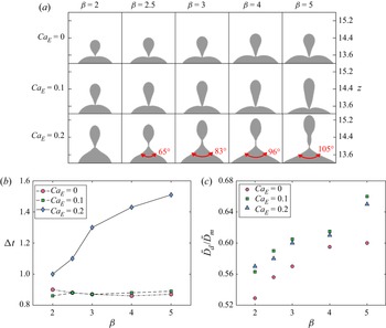
While β and CaE can influence pinch-off as well as the daughter drop size, a comprehensive picture of the coalescence subjected to the variations in both can be intriguing, as shown in figure 11(a). Remarkable alterations in the pinch-off modes can be observed with an increase in CaE. For CaE ≤ 0.1, in all cases, a dimple (or crater) forms on the father drop at the onset of pinch-off. Such pinch-off events have been observed to be common in most of the previously reported studies (Blanchette & Bigioni Reference Blanchette and Bigioni2009; Ray et al. Reference Ray, Biswas and Sharma2010; Garzon et al. Reference Garzon, Gray and Sethian2018). Counterintuitively, the pinch-off mode shifts to a cusping-like mode when CaE is increased to 0.2. In such cases, the top portion of the father drop elevates, transforming into conical ends prior to neck collapse. Note that the angle of these conical ends increases with increasing β. Another peculiarity can be found in terms of the time taken for pinch-off (Δt) (see figure 11b). For the former pinch-offs (i.e. for CaE ≤ 0.1), while Δt ≈ 0.87 for all β, for the cusping modes Δt is much longer and monotonically increases with β. Following the above discussion, it can be said that the mechanism responsible for cusping is similar to that inducing end-pinching (see figure 10), except that the latter is most likely to occur at a much higher CaE as it requires substantial elongations in the father drop also, as discussed before. From figure 11(a), one important feature that can be noted is that, for higher β (e.g. β = 5), increase in CaE produces noticeably longer daughter drops, which are highly unstable and may undergo capillary-driven breakup before or after pinch-off.
(a) Pinch-off events for various pairs of β and CaE. (b) Coalescence time Δt and (c) daughter drop size as functions of β for different CaE. The parameters considered are R = 10, S = 2.3, Ohi = 0.005, Ohe = 0.0002, Bo = 0.32 and A = 0.998.

Figure 11(c) depicts the effect of β on non-dimensional daughter drop size  $({\bar{D}_d}/{\bar{D}_m})$ for different CaE. For all CaE, increase in β leads to bigger daughter droplets. Deka et al. (Reference Deka, Biswas, Chakraborty and Dalal2019), in their numerical analysis, demonstrated that increase in β lessens the neck expansion, thus decreasing the fluid drainage to the father drop. To this, as we have already discussed, increase in CaE further restricts the flow rate and thus increases
 ${\bar{D}_d}/{\bar{D}_m}$. However, altering CaE from 0.1 to 0.2 leads to negligible variation in
 ${\bar{D}_d}/{\bar{D}_m}$. This is for the reason that, as compared with CaE = 0 and 0.1, the time needed for pinch-off for
 $Ca_{E} = 0.2$ is much longer. Accordingly, more fluid is transported to the father drop, even if the flow rate is low.
5.2. Influence of the relative electrical properties
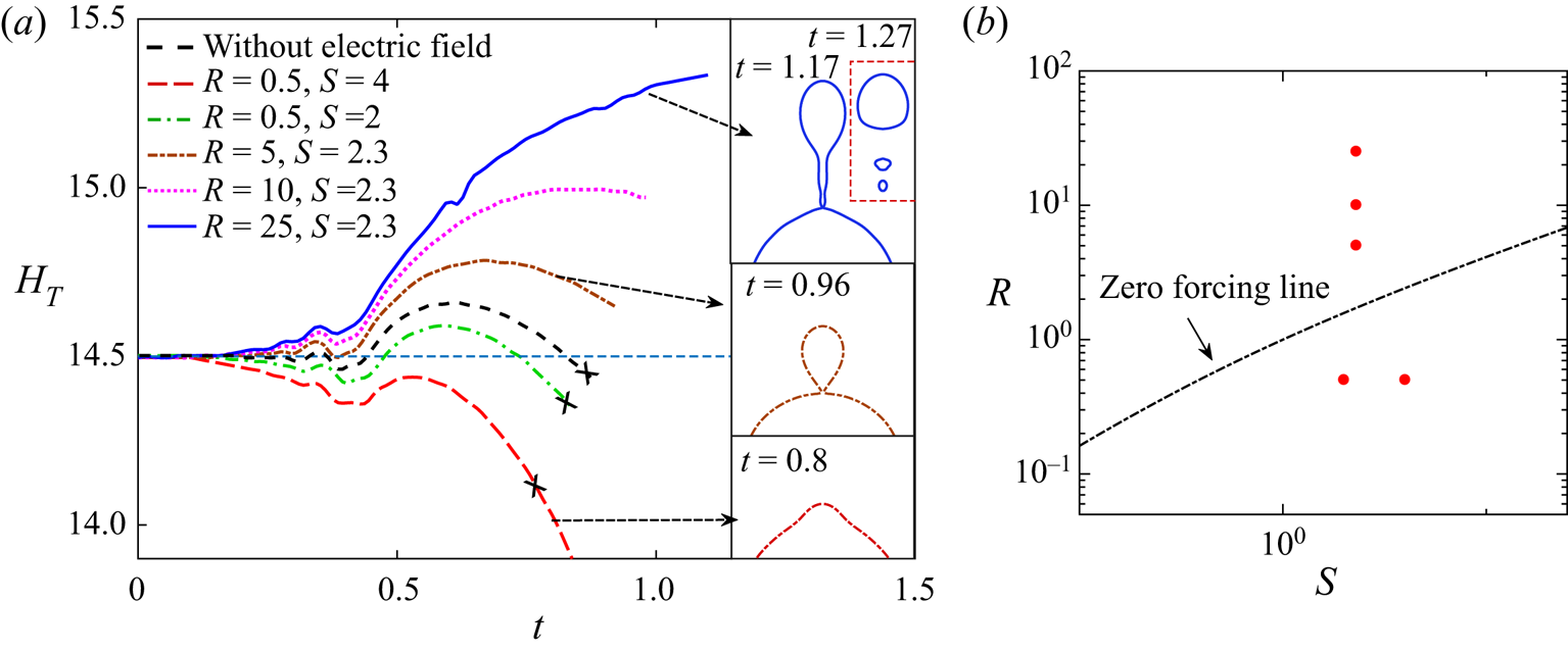
As the electric stress is characterized by (R, S), it is imperative to investigate the effect of these parameters on the observed coalescence dynamics. In figure 12(a), we delineate the coalescence dynamics in terms of the temporal variation of the drop apex for different sets of electrical properties (R, S) and its consequence for pinch-off, considering β = 2, CaE = 0.2 and Ohi = 0.01. It is pointed out that as the deviation of R/S from unity increases, the temporal characteristic of HT shows higher deviation from the same obtained for CaE = 0. For R/S > 1, while this deviation in HT is positive, for R/S < 1 it is negative. For the systems (R, S) = (5, 2.3), (R, S) = (10, 2.3) and (R, S) = (25, 2.3), using (4.2), the values of normal electric stresses (τE) at the apex are obtained as 0.476, 0.668 and 0.80, respectively. This explains the rise in HT with increasing R/S. Conversely, for cases with R/S < 1, decrease in R/S causes larger reduction in HT as the dimensionless τE for (R, S) = (0.5, 2) and (R, S) = (0.5, 4) are found to be 0.511 and −1.144, respectively. By looking into the locations of these said systems in phase space with reference to the zero net force line (see (4.3)), as depicted in figure 12(b), it can be inferred that as we move far from the said line, the electric-field-induced modulations become more important. The sign and the relative magnitude of the various electric stresses that define the resulting interplay have already been discussed in § 4.
(a) Temporal variation of the drop apex (HT) under electric field for different electrical properties (R, S). The insets display the outcomes of coalescence for different (R, S). The HT versus t curves marked with crosses indicate non-pinching modes. The parameters considered are β = 2, CaE = 0.2, Ohi = 0.01, Ohe = 0.0002, Bo = 0.32 and A = 0.998. (b) Location of the systems considered in (a) with reference to the zero net force line in the (R, S) phase plot.

From the insets provided in figure 12(a), it can be observed that for the considered parameters, the systems with R/S > 1 exhibit pinch-off, unlike for the case without electric field (non-pinching modes are marked with a cross). For (R, S) = (5, 2.3), while the daughter drop is close to spherical shape, for (R, S) = (25, 2.3), pinch-off generates a long drop with a tail-like structure. This tail eventually becomes detached and breaks into tiny droplets as shown in the inset. In figure 11(a), we have presented a similar daughter drop topology for lower R/S values (i.e. R = 10 and S = 2.3) and higher values of β. A comparison between figures 11(a) and 12(a) signifies that EHD–capillary pulls of comparable magnitude, creating long unstable daughter droplets, can be generated even for lower values of β, by increasing R/S.
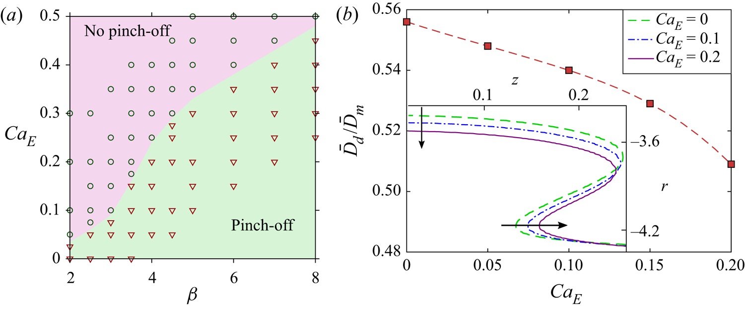
For the cases with R/S < 1, no pinch-offs are obtained (marked with a cross), owing to weak upward pull. In fact, the system (R, S) = (0.5, 4) exhibits complete coalescence. For this system, the electric stress significantly suppresses the capillary pull, not allowing the apex to move upwards. As a result, the mother drop entirely merges with the father drop within a much shorter time (at  $t \approx 0.8$) without showing any sign of partial coalescence. The drop evolution leading to complete coalescence is provided in the next section while discussing the coalescence cascade.
The electric-field-mediated coalescence for the cases of R/S < 1 is elucidated in more detail in figure 13, considering the system (R, S) = (0.5, 2) and Ohi = 0.01. Figure 13(a) depicts the phase diagram in  $C{a_E}$–
 $\beta$ parametric space demarking the pinch-off regimes. This demonstrates that the increase in CaE remarkably increases the minimum (or critical) value of the parent ratio (βc) required for pinch-off, owing to the additional capillary energy required for overcoming the effect of electrically induced perturbation. This qualitative relation between βc and CaE is opposite to that obtained for R/S > 1, where βc is directly proportional to the negative exponent of CaE. Consequently, on increasing CaE, while for R/S > 1, βc tends to unity (see figure 7), for R/S < 1, βc can deviate up to O(10), where the drop–drop system can be typically considered as a drop–pool system. It is worth mentioning that an increase in Ohi can further increase βc by providing higher viscous resistance to the capillary pull.
(a) The  $C{a_E}$–
 $\beta$ phase diagram indicating no-pinch-off and pinch-off regimes. (b) Effect of electric capillary number CaE on daughter drop size for β = 4. The inset compares the shapes of the drop for different CaE at Δt = 0.75. The parameters considered are R = 0.5, S = 2, Ohi = 0.01, Ohe = 0.0002, Bo = 0.32 and A = 0.998.

Figure 13(b) shows the effect of CaE on the non-dimensional daughter drop size  $({\bar{D}_d}/{\bar{D}_m})$ in the pinch-off regime for β = 4. Unlike the case of R/S > 1, here we obtain a decrease in
 ${\bar{D}_d}/{\bar{D}_m}$ with an increase in CaE. As the downward electric pull lowers the maximum limit of the drop apex, it causes an early vertical collapse, as shown in figure 12. Moreover, on analysing the contours at t = 0.75 (during the vertical collapse phase), we observe that the increase in CaE results in wider necks, as opposed to the thinner necks obtained for the case of R/S > 1. As the neck becomes wider, the local pressure (pneck) reduces as discussed before, resulting in slower horizontal collapse. For example, for CaE = 0, 0.1 and 0.2, pinch-off occurs at Δt = 0.86, 0.9 and 0.96, respectively. The augmented cross-sectional area of the neck and higher pre-pinch-off time enhance the fluid displacement from the mother drop, leading to reduction in
 ${\bar{D}_d}/{\bar{D}_m}$.
5.3. Coalescence cascade
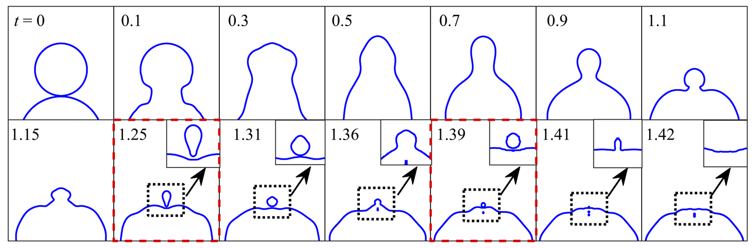
The smaller drops (or daughter drops) generated from partial coalescence fall onto the bigger drop to initiate a self-similar coalescence event. This process may continue several times until the formation of a single entity, thus generally termed as a coalescence cascade. Here we compare the solely capillary-driven coalescence cascade (when CaE = 0) with the electrically mediated one considering R/S > 1 and R/S < 1.
Figure 14 depicts the results for CaE = 0, β = 1.6 and Ohi = 0.005. In this case, the first pinch-off does not occur, and the neck starts to widen again, similar to that observed in the initial stage. This initiates the second-stage coalescence, where the capillary wave deforms the drop again into a cylindrical protrusion, followed by the vertical collapse phase. Interestingly, the second pinch-off successfully takes place, generating a droplet of size 0.19. Similar mid-stage pinch-off modes were previously reported by Zhang et al. (Reference Zhang, Li and Thoroddsen2009), which can be attributed to the fact that in the second stage, the attached daughter drop (that acts like the mother drop) maintains a higher parent ratio, β > βc, with the father drop. The third stage of coalescence starts at time t = 1.315 from which a tertiary droplet is produced at  $t \approx 1.39$ with
 ${\bar{D}_d}/{\bar{D}_m}$
 $( = 0.077)$ almost 0.4 times the preceding mother drop size. As this drop's size is very small, it completely merges with the bigger drop in the next stage. In the current case, a four-stage coalescence is observed with two pinch-offs; however, by increasing β, more stages can be obtained with more pinch-offs. The maximum number of coalescence stages reported in the literature, in solely capillary-driven systems, is six, which was observed by Thoroddsen & Takehara (Reference Thoroddsen and Takehara2000) for a drop–pool system.
Coalescence cascade of drops for parent ratio β = 1.6 in the absence of electric field. The parameters considered are Ohi = 0.005, Ohe = 0.0002, Bo = 0.32 and A = 0.998. The panels capturing the occurrence of pinch-off are marked with dashed lines in red colour for better visualization.

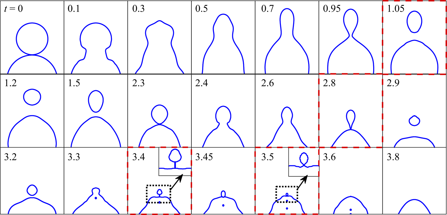
Figure 15 shows the influence of electric field on a cascade for R = 10, S = 2.3 and CaE = 0.2, with other parameters remaining the same. Here, significant alterations in the cascade process are found. A five-stage coalescence is obtained, including pinch-off in the first four stages. The sizes of the daughter drops found in successive stages are 0.53, 0.32, 0.16 and 0.076. For R/S > 1, as the electric forcing lowers the critical parent ratio, it leads to the transition from no pinch-off to pinch-off (see figures 7 and 8a) as well as producing daughter drops larger than that obtained for CaE = 0 in the respective stages. As a post-pinch-off event, the daughter drop exhibits movement in the upward direction while undergoing prolate–oblate oscillatory deformations until it falls back to meet the father drop. Interestingly, as the electric field's presence results in a larger daughter drop, it displaces to a greater distance due to higher inertia. As a consequence, for CaE = 0.2 the time gap between the first pinch-off and the initiation of the second stage is found to be very high, i.e. almost 1.35, which makes the total coalescence process highly time-consuming. It also can be noticed that the values of daughter to mother droplet size ratios in each stage fall in the range of 0.55 + 0.05. From the times mentioned in each panel of figure 15, it is apparent that the higher stages of cascade occur over progressively shorter times. The reason is that the time scale for the completion of the nth stage (ΔtN) is typically of the order of 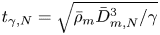 ${t_{\gamma ,N}} = \sqrt {{{\bar{\rho }}_m}\bar{D}_{m,N}^3/\gamma }$, where
 ${\bar{D}_{m,N}}$ is the size of the mother drop in the Nth stage or the size of the daughter drop in the (N − 1)th stage. Thus, ΔtN can be calculated as
 $\varDelta {t_N} \approx {({\bar{D}_{m,N}}/{\bar{D}_{m,1}})^{3/2}}\varDelta {t_1}$, where
 ${\bar{D}_{m,1}}$ is the size of the mother drop at the initial stage. Thus, as
 ${\bar{D}_{m,N}}/{\bar{D}_{m,1}}$ decreases at each stage as mentioned above, the time needed for the completion of the cascade phenomenon also decreases perceptibly.
Coalescence cascade of drops for the system (R, S) = (10, 2.3) and parent ratio β = 1.6. Other parameters considered are CaE = 0.2, Ohi = 0.005, Ohe = 0.0002, Bo = 0.32 and A = 0.998. The panels capturing the occurrence of pinch-off are marked with dashed lines in red colour for better visualization.

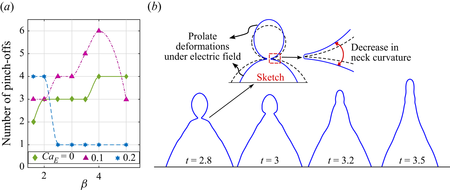
Although figures 14 and 15 suggest an increase in the number of coalescence cascade stages under an electric field, in reality the coalescence cascade for the different parent ratios may emerge to be contrary to that intuitive perception, as demonstrated in figure 16(a). From the figure, it is evident that for CaE = 0, the number of pinch-offs (N) can be increased by increasing the value of β. As the increase in β produces larger daughter droplets after the first stage, it reduces the effective Ohneseorge number, i.e.  $Oh_i^{eff} = {\bar{\mu }_i}/\sqrt {{{\bar{\rho }}_m}{{\bar{D}}_d}\gamma }$, reducing the viscous resistance in the second stge. Owing to self-similarity, the viscous resistance in the successive stages is also relatively less, favouring more pinch-offs. However, the discontinuous variation in N indicates the existence of a critical value of β for each N. Additionally, between the two successive critical parent ratios, there exists a range of β producing the same number of pinches. Note that a maximum of four pinch-offs is observed for β = 5 and CaE = 0.
(a) Number of pinch-offs before complete coalescence for different parent ratios β and electric capillary numbers CaE. The system (R, S) = (10, 2.3) is considered along with Ohi = 0.005, Ohe = 0.0002, Bo = 0.32 and A = 0.998. (b) Second-stage coalescence for β = 3 and CaE = 0.2. Schematic representation is provided as the inset to explain the reason behind the non-pinching mode.

On increasing CaE to 0.1, N increases considerably for all β up to β = 4. It is noteworthy that a maximum of six pinch-offs or alternatively a seven-stage coalescence is observed under electric field, for β = 4 and CaE = 0.1 (see the supplementary movie available at https://doi.org/10.1017/jfm.2022.1096), beyond the maximum numbers of stages observed previously by Thoroddsen & Takehara (Reference Thoroddsen and Takehara2000) for drop–pool systems. Surprisingly, when β is increased to 5, we observe fewer pinch-offs (N = 3), which is even fewer than that found for the corresponding case in the absence of electric field (N = 4). The non-monotonic trend becomes more evident at higher CaE. For  $\beta \le 2$, the pinch-offs obtained for CaE = 0.2 are more in number as compared with that obtained for CaE = 0. However, for β > 2, N dramatically decreases to unity, signifying the occurrence of complete coalescence in the second stage.
To explain the distinctive and apparently non-intuitive cascading trends, we illustrate the drop evolution in the second stage for CaE = 0.2 and β = 3 in figure 16(b). Unlike the first stage, the drops at the initiation of the second stage are prolate-shaped owing to electric-field-induced deformations for systems with R > S (Taylor Reference Taylor1966; Lac & Homsy Reference Lac and Homsy2007; Behera, Mandal & Chakraborty Reference Behera, Mandal and Chakraborty2019). Accordingly, the initial neck curvature at the onset of second stage reduces, leading to weakening of capillary-wave propagation as demonstrated schematically in the inset. Importantly, as the size of the mother drop reduces by almost (0.5)N times in the Nth stage, the effective electric capillary number  $Ca_E^{eff} = (\bar{D}_m^N{\bar{\varepsilon }_e}\bar{E}_0^2/\gamma )$ reduces by the same fraction. Thus, the electric-field-induced deformation of the mother drop in the second stage is significantly small, contributing less to the variation in neck curvature. Conversely, the father drop, which is of larger size, deforms more (
 $Ca_E^{eff}$ for the father drop is
 ${\bar{D}_f}{\bar{\varepsilon }_e}\bar{E}_0^2/\gamma$), as evidenced from figure 16(b), which thus plays the key role in reducing the neck curvature. Moreover, the fluid transport from the mother to the father drop leads to increase in Df and thereby
 $Ca_E^{eff}$ for the father drop. At a certain stage if
 $Ca_E^{eff}$ crosses the threshold limit due to either an increase in electric field strength or size of the father drop, the father drop may exhibit unstable EHD elongations, inhibiting pinch-off as shown earlier in figure 10(b).
Figure 17 reveals the cascading trends for the system with R/S < 1 considering R = 0.5, S = 2, β = 1.6, CaE = 0.2 and Ohi = 0.005. Surprisingly, here no cascading is observed. Instead, the mother drop completely merges with the father drop. The contour analysis shows that at t = 0.7, the height of the protrusion above the father drop is much shorter compared with the previous two cases. Owing to the shorter length, the protrusion becomes highly stable resulting in insignificant horizontal collapse. In fact, the neck cannot be identified after t = 0.7. As a result, the first pinch-off does not occur. The top of the protrusion, where the curvature is maximum, continuously falls, pushing the fluid into the father drop and leading to complete coalescence without going to the further stages.
Coalescence cascade of drops for the system (R, S) = (0.5, 2) and parent ratio β = 1.6. The other parameters considered are CaE = 0.2, Ohi = 0.005, Ohe = 0.0002, Bo = 0.32 and A = 0.998.

6. Conclusions
The partial coalescence of unequal-sized drop pairs under uniform electric field is studied in the inertio-capillary regime, using comprehensive numerical simulations. The effects of electric field on the pinch-off of daughter droplets, in both the first and successive stages, are highlighted, and the mechanisms orchestrating the alterations are discussed. The key findings from the present study are summarized below.
The drop–drop coalescence gets hydrodynamically modulated by the imbalance between the capillary force generated at the contact region, resistive viscous force and gravitational force, with this interplay being significantly alterable via electrically mediated interactions. This decisive controllability stems from the fact that the generation of the secondary drop requires a delay in the vertical collapse of the liquid column formed due to the interfacial tension-driven stretching induced by the capillary wave, depending on the relative electrical properties of the droplet and the carrier phases towards altering the pinch-off dynamics. Towards that end, if R/S > 1, the electric stress strengthens the capillary stress causing higher elongation of the mother drop, thereby favouring pinch-off by delaying a vertical collapse. Conversely, if R/S < 1, the electric stress hinders the elongation and opposes pinch-off. Notably, pinch-off occurs only if the parent ratio is above the critical limit. For R/S > 1 (or R/S < 1), an increase in electric capillary number (CaE) can cause a decrease (or increase) in the critical parent size ratio (βc), and drastically alter the physical nature of its dependence on the Ohnesorge number. In the process, it is plausible to achieve this critical onset at a substantially reduced value of the parent size ratio, as compared with the lowest limiting value of 1.55 reported earlier albeit without EHD interactions (Zhang et al. Reference Zhang, Li and Thoroddsen2009).
In the limit of β > βc, increase in CaE increases (or decreases) the size of the daughter drop for R/S > 1 (or R/S < 1). In the case of R/S > 1, small limits of CaE can cause the formation of a dip on the father drop at the onset of pinch-off. Whereas, for higher CaE values, pinch-off occurs by a cusping kind of mode producing long unstable drops with a tail-type structure that eventually breaks into multiple smaller drops. Increasing CaE beyond a threshold limit can cause large axial elongations in the mother drop and the father drop, with continued contact. Under such a scenario, the drop experiences EHD–capillary pull from both ends, which leads to end-pinching-type breakup and the formation of satellite drops at each end. However, during the intermediate stage, the drop may also exhibit tip streaming.
The coalescence dynamics in the successive stages is found to be self-similar. For R/S > 1, the electric field not only increases the daughter drop's size but also increases the number of stages. As a consequence, the total coalescence time increases. We observed that for R/S > 1, a maximum of seven stages of coalescence becomes possible under an electric field, for the chosen set of parameters. Increasing the field strength or the parent ratio beyond a certain limit has further been shown to reduce the numbers of cascade stages contrary to common intuition, owing to large prolate deformation of the father drop that reduces the initial neck curvature. On the other hand, for R/S < 1, the number of successive stages may reduce or not even appear owing to partial–complete coalescence transition, consequently reducing the coalescence time. These results imply that the applied electric field not only may influence the inception of the coalescence phenomena, but also may strongly dictate the downstream collision cascades in a non-trivial manner during the occurrence of partial coalescence. Accordingly, via exploring the intertio-capillary regime over favourable parametric spaces, decisive morphological transitions of a multi-drop collection may be exclusively programmed, opening up new control mechanisms of the observed transport phenomena having far-reaching implications in several spheres of engineering, nature and biology.
Supplementary movie
Supplementary movie is available at https://doi.org/10.1017/jfm.2022.1096.
Acknowledgements
S.C. acknowledges the SERB, Department of Science and Technology, Government of India, for Sir J.C. Bose National Fellowship.
Declaration of interests
The authors report no conflict of interest.
Appendix A. Grid convergence study
Figure 18 illustrates the grid convergence study performed by simulating the coalescence problem for (R, S) = (10, 2.3), β = 2, CaE = 0.1, Ohi = 0.005, Ohe = 0.0002, Bo = 0.32 and A = 0.998. Comparing the temporal evolution of drop apex position, it is evident that increasing the grid level from 11 to 12 causes a negligible increase in HT(t). Consequently, for grid-level 12, the obtained contour at the time of pinch-off is almost the same as that obtained for level 11. Therefore, to reduce the computational cost without sacrificing accuracy, grid-level 11 is used. The far-field grid is set to level 6 for both cases.
Transient variation of the drop apex position during drop–drop coalescence for the system (R, S) = (10, 2.3) and parent ratio β = 2. Other parameters considered are CaE = 0.1, Ohi = 0.005, Ohe = 0.0002, Bo = 0.32 and A = 0.998.

Appendix B. Comparison with potential-flow-based analysis
Since the Ohnesorge numbers are negligibly small in the inertio-capillary regime, Garzon et al. (Reference Garzon, Gray and Sethian2018) dropped out the viscous effects from their numerical model, which can successfully explain the coalescence dynamics for very low-viscosity liquids like alcohol and water. However, for relatively more viscous liquids such as oil, neglecting the viscous effects altogether may result in significant inconsistencies in the model predictions, even in the interio-capillary regimes, defying common intuition. This may be exemplified by appealing to the results outlined in § 4. For illustration, we consider CaE = 0.05, R = 100 and S = 1. The chosen value of R as well as the fact that  $R \gg 1$ are reminiscent of the situation of a conducting drop placed in a perfectly dielectric (or insulating) medium (Ha & Yang Reference Ha and Yang2000; Karyappa et al. Reference Karyappa, Deshmukh and Thaokar2014), as considered by Garzon et al. (Reference Garzon, Gray and Sethian2018).
Figures 19(a) and 19(b) depict the effect of viscosity on the transient evolution of the drop apex (HT) in the absence and presence of the electric field, respectively. These results reveal that an excellent agreement with the potential-flow-based predictions may be obtained when Ohi and Ohe are of  $O({10^{ - 3}})$. However, for
 $O{h_e}\sim O({10^{ - 2}})$, the viscous effects may alter the value of HT, particularly during the later transients, which may in turn affect the generation of daughter drop and the downstream dynamic events in succession. As reported by Blanchette & Bigioni (Reference Blanchette and Bigioni2009), in the case of drop–pool systems where β → ∞, in the absence of electric field, pinch-off cannot occur if
 $O{h_i} > 0.03\ (O{h_i}\sim O({10^{ - 2}}))$. Therefore, for finite β, the critical limit of Ohi must be less than 0.03, which agrees well with our results provided in figure 7. Additionally, with the increase in viscosity ratio, i.e. Ohi/Ohe, the electric-field-induced deformations can significantly vary, as reported by several researchers (Ha & Yang Reference Ha and Yang2000; Lac & Homsy Reference Lac and Homsy2007), which cannot be predicted by the potential flow model.
Effect of viscous forces on transient variation in drop apex for (a) CaE = 0 and (b) CaE = 0.05. The other parameters considered are β = 2.63, R = 100, S = 1, Bo = 0.32 and A = 0.998. We compare our numerical results with the same obtained from the potential flow model of Garzon et al. (Reference Garzon, Gray and Sethian2018).

The alteration in drop apex owing to viscous effects can be better realized by imposing force balance on the protrusion, analogous to the formulation of capillary filling problem (Dhar et al. Reference Dhar, Mukherjee, Raj M and Chakraborty2019), where the capillary stress  $({\tau _\gamma })$ drives the upward motion and the viscous stress
 $({\tau _v})$ resists it, as shown schematically in figure 4(c). Assuming that the protrusion is cylindrical throughout the upward stretching, the dimensional force balance condition can be written as
 \begin{equation}\frac{\textrm{d}}{{\textrm{d}\bar{t}}}\left( {{{\bar{\rho }}_i}{\rm \pi} \bar{R}_n^2\Delta {{\bar{H}}_T}\frac{{\textrm{d}\Delta {{\bar{H}}_T}}}{{\textrm{d}\bar{t}}}} \right) = \int {({{\bar{\tau }}_\gamma } - {{\bar{\tau }}_v} + {{\bar{\tau }}_E})\,\textrm{d}\bar{A}} ,\end{equation}
where  $\textrm{d}\bar{A} = {\rm \pi}{\bar{R}_n}\ \textrm{d}\bar{z}$ is the infinitesimal surface area. Note that the effect of gravitational force is neglected here, considering negligible density variation. To establish a qualitative relation between
 $\Delta {\bar{H}_T}$ and Oh in a simplified manner, we perform scaling analysis, where the various forcing effects can be scaled as follows:
 \begin{equation}{\bar{\tau }_\gamma }\sim \gamma /\Delta {\bar{H}_T},\quad {\bar{\tau }_v}\sim \bar{\mu }\partial \bar{u}/\partial \bar{z}\sim \frac{{({{\bar{\mu }}_i} + {{\bar{\mu }}_e})}}{{\Delta {{\bar{H}}_T}}}\left( {\frac{{\Delta {{\bar{H}}_T}}}{{{{\bar{t}}_\gamma }}}} \right),\quad {\bar{\tau }_E}\sim {\bar{\varepsilon }_e}\bar{E}_0^2.\end{equation}
Here, the viscous stress includes the resistance offered by both fluids. Using the above scales, (B1) can be transformed to
 \begin{equation}\frac{{{{\bar{\rho }}_i}{{\bar{R}}_n}\Delta {{\bar{H}}_T}}}{{\bar{t}_\gamma ^2}} = {C_1}\frac{\gamma }{{\Delta {{\bar{H}}_T}}} - {C_2}\frac{{{{\bar{\mu }}_i} + {{\bar{\mu }}_e}}}{{{{\bar{t}}_\gamma }}} + {C_3}{\bar{\varepsilon }_e}\bar{E}_0^2,\end{equation}
where C 1, C 2 and C 3 are scaling constants. Here, C 1, C 2 > 0, whereas the sign of C 3 depends on the sign of R/S − 1. Now, using  ${\bar{t}_\gamma } = \sqrt {{{\bar{\rho }}_m}\bar{D}_m^3/\gamma } $ and rearranging the terms, the normalized and simplified form of (B3) can be written as
 \begin{equation}{R_n}\Delta H_T^2 - ( - {C_2}(O{h_i} + O{h_e}) + {C_3}C{a_E})\Delta {H_T} - {C_1} = 0.\end{equation}
The solution to the above quadratic equation can be obtained as
 \begin{equation}\Delta {H_T} = \frac{{ - {C_2}(O{h_i} + O{h_e}) + {C_3}C{a_E} + \sqrt {{{({C_2}(O{h_i} + O{h_e}) - {C_3}C{a_E})}^2} + 4{C_1}{R_n}} }}{{2{R_n}}},\end{equation}
which shows that ΔHT is a function of Oh. In the limit  $O{h_i},O{h_e} \to 0$, the apex height can be obtained as
 $\Delta H_T^0 = ({C_3}C{a_E} + \sqrt {{{({C_3}C{a_E})}^2} + 4{C_1}{R_n}} )/2{R_n}$. Thus, variation in CaE alone can lead to variation in apex height. Furthermore, the mathematical relation given in (B5) shows that an increase in
 $(O{h_i},O{h_e})$ will result in
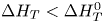 $\Delta {H_T} < \Delta H_T^0$, which agrees well with our numerical results. Physically, an increase in Ohnesorge numbers amplifies the viscous resistance to the capillary-driven flow. Thus, the apex attains a lesser height as shown in figure 19. Importantly, in the other extreme limit, i.e. for finite Ohnesorge numbers, (B5) predicts
 $\Delta {H_T} \approx 0$. This means that in the viscous-dominated regime, no protrusion is formed, which agrees with the reported experimental observations (Luo et al. Reference Luo, Yin, Yan, Huang, Yang and He2018; Anand et al. Reference Anand, Roy, Naik, Juvekar and Thaokar2019). Another interesting thing to note here is that for low Rn, HT is higher. Similar characteristics can be found in the numerical study of Deka et al. (Reference Deka, Biswas, Chakraborty and Dalal2019) for the cases of high β. Also, in figure 6 it can be seen that an increase in Ohi leads to an increase in Rn and, simultaneously, a decrease in HT. Thus, our mathematical modelling is able to predict the effects of various geometric and forcing parameters on the morphological variations occurring during drop coalescence in the inertio-capillary regime, in a physically consistent manner.