

INTRODUCTION
Tectonic plate motion along continental transform boundaries is typically confined within strike-slip faulting zones while additional deformation may be dispersed to the adjacent regions (Wilcox et al., Reference Wilcox, Harding and Seely1973). Spatial deformation in such settings may be expressed by subordinate strike-slip faults, normal faults, reverse faults, low-angle thrust faults, flexures parallel or oblique to the original displacement direction, rhomb-shaped grabens, and/or push-up ridges (Sylvester, Reference Sylvester1988). The form and orientation of these deformation features are governed by the regional stress tensor, which may induce local stress fields expressed by divergence or convergence motion (Wilcox et al., Reference Wilcox, Harding and Seely1973). The regional effect of strike-slip–related deformation activity may extend up to tens of kilometers (Sylvester, Reference Sylvester1988) and tends to narrow as a function of cumulative offset (Wesnousky, Reference Wesnousky1988), consequently resulting in concentration of the slip displacement along a few closely spaced faults. Changes in orientation of the regional stress tensor along the transform boundary may disrupt the concentration process and reinitiate the spatial spreading of deformation (Wilcox et al., Reference Wilcox, Harding and Seely1973).
The Dead Sea Transform (DST) is the boundary between the Arabian plate and the Sinai subplate (Garfunkel, Reference Garfunkel1970, Reference Garfunkel1981; Fig. 1). The DST extends from the Red Sea in the south to the East Anatolian Fault in the north (Quennell, Reference Quennell1958). Left-lateral movement along this plate boundary began in the middle Miocene and resulted in cumulative sinistral offset of approximately 105 km (Freund et al., Reference Freund, Garfunkel, Zak, Goldberg, Weissbrod and Derin1970; Garfunkel, Reference Garfunkel1981; Joffe and Garfunkel, Reference Joffe and Garfunkel1987; Eyal, 1996; Ben-Avraham et al., Reference Ben-Avraham, Garfunkel and Lazar2008 and references therein). Since the Pliocene, the southern segment of the DST was subject to slight plate separation, resulting in the formation of rift valleys (i.e., the Jordan Valley and the Arava Valley) (Eyal et al., Reference Eyal, Eyal, Bartov and Steinitz1981; Garfunkel, Reference Garfunkel1981; Bartov, Reference Bartov1994; Matmon et al., Reference Matmon, Fink, Davis, Niedermann, Rood and Frumkin2014).
(color online) Regional tectonic setting. Arrows at plate boundaries indicate relative sense of motion. The study area is marked with a black open box.

The Arava Valley, a part of the southern segment of the DST (Fig. 1), extends from the northern end of the Gulf of Eilat to the Dead Sea basin (Garfunkel, Reference Garfunkel1988). Quaternary motion along the Arava segment of the DST has been conventionally viewed as partitioned into marginal normal faults that accommodate vertical deformation and sinistral strike-slip faults along the center of the valley that accommodate horizontal deformation (Eyal et al., Reference Eyal, Eyal, Bartov and Steinitz1981; Garfunkel, Reference Garfunkel1981; Fig. 2). Several of the marginal faults include both vertical and horizontal displacement components (Garfunkel, Reference Garfunkel1970).
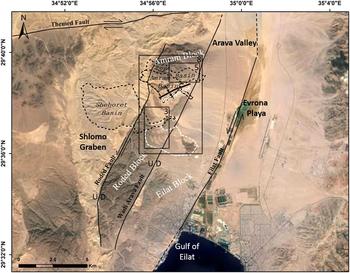
(color online) Satellite image of the southern Arava Valley and its western margin (modified from https://maps.google.com). The present-day catchments of the basins examined in this study are outlined in black dashed line. The white dashed line outlines an area no longer draining into the Shehoret basin. Boxes indicate locations of Figures 3, 5, and 8. ZSF, Zefunot Southern Fork.

The width of deformation associated with the initial stages of motion along the DST reached tens of kilometers (Eyal et al., Reference Eyal, Eyal, Bartov and Steinitz1981; Marco, Reference Marco2007; Beyth et al., Reference Beyth, Eyal and Garfunkel2012). With the continuation of lateral movement during the late Miocene, deformation appears to have become more localized and concentrated within the valley center of the Arava segment (Marco, Reference Marco2007). Paleoseismic studies along this segment of the DST (e.g., Gerson et al., Reference Gerson, Grossman, Amit and Greenbaum1993; Amit et al., Reference Amit, Harrison, Enzel and Porat1996, Reference Amit, Zilberman, Enzel and Porat2002; Klinger et al., Reference Klinger, Avouac, Dorbath, Karaki and Tisnerat2000), geomorphic investigations (e.g., Amit et al., Reference Amit, Zilberman, Porat and Enzel1999; Le Béon et al., Reference Le Béon, Klinger, Mériaux, Al‐Qaryouti, Finkel, Mayyas and Tapponnier2012), and interpretation of historical seismic records (e.g., Amiran et al., Reference Amiran, Arieh and Turcotte1994; Niemi et al., Reference Niemi, Harrison and Atallah1997; Ambraseys and Jackson, Reference Ambraseys and Jackson1998; Guidoboni and Comastri, Reference Guidoboni and Comastri2005; Hamiel et al., Reference Hamiel, Amit, Begin, Marco, Katz, Salamon, Zilberman and Porat2009; Porat et al., Reference Porat, Duller, Amit, Zilberman and Enzel2009), together with geophysical (e.g., Frieslander, Reference Frieslander2000; Haberland et al., Reference Haberland, Maercklin, Kesten, Ryberg, Janssen, Agnon, Weber, Schulze, Qabbani and El-Kelani2007), geodetic (e.g., Le Beon et al., Reference Le Beon, Klinger, Amrat, Agnon, Dorbath, Baer, Ruegg, Charade and Mayyas2008; Al Tarazi et al., Reference Al Tarazi, Abu Rajab, Gomez, Cochran, Jaafar and Ferry2011), and remote-sensing investigations (e.g., Slater and Niemi, Reference Slater and Niemi2003; Baer et al., Reference Baer, Funning, Shamir and Wright2008), consistently point toward concentration of late Pleistocene–Holocene activity within a ~2-km-wide zone along the center of the valley.
We present recent changes in geomorphic features, reconstruct past drainage system flow patterns, and infer from these the tectonic deformation that occurred along the western margin of the Arava Valley during the late Pleistocene to Holocene. We utilize our findings to challenge the previous hypothesis regarding the width of deformation along the southern DST and redetermine the extent of off-axis tectonic deformation in this region during the Quaternary.
Tracing tectonic deformation along transform boundaries by geomorphic evidence is widely practiced in tectonically active regions (e.g., Sieh and Jahns, Reference Sieh and Jahns1984; Ginat et al., Reference Ginat, Enzel and Avni1998; Matmon et al., Reference Matmon, Schwartz, Finkel, Clemmens and Hanks2005, Reference Matmon, Schwartz, Haeussler, Finkel, Lienkaemper, Stenner and Dawson2006; Castelltort et al., Reference Castelltort, Goren, Willett, Champagnac, Herman and Braun2012), including the southern segment of the DST (e.g., Ginat et al., Reference Ginat, Beyth and Crouvi2009; Le Béon et al., Reference Le Béon, Klinger, Mériaux, Al‐Qaryouti, Finkel, Mayyas and Tapponnier2012). Although these and other studies typically focus on deformed geomorphic features that directly cross the strike-slip faults, our study focuses on the more subtle and indirect influence that strike-slip deformation can exert on the local geomorphology—fluvial fan systems in this case.
Several aggradation-degradation cycles are present in the investigated drainage basins, which most likely express significant shifts in sediment generation, transport, and deposition capacities that may have been driven by climatic fluctuation. However, we do not discuss the reasons and driving forces that caused such shifts. Rather, we use the ages and locations of the various sedimentary units as points that indicate the shift over time of active channels in the investigated drainage basins. We put emphasis on the lateral shifts over time in channel flow direction and attribute them to Pleistocene-Holocene tectonic deformation.
STUDY AREA
This study focuses mainly on two catchments (with a third briefly described), located approximately 10 km north of the Gulf of Eilat (Fig. 2), that span a set of adjacent structural blocks separated by subparallel faults along the western margin of the southern Arava Valley (the Roded, Eilat, and Amram blocks) (Garfunkel, Reference Garfunkel1970). The width of these structural blocks ranges from a few hundred meters to 1.5 km, and they are 3 to 7 km long (Fig. 2). Vertical offsets of hundreds of meters and sinistral, approximately north–south movement between these blocks were previously described (i.e., the Roded and the Wadi Arava Faults; Garfunkel, Reference Garfunkel1970; Frieslander, Reference Frieslander2000; Beyth et al., Reference Beyth, Eyal and Garfunkel2012).
The dextral, strike-slip Themed Fault, which is part of the Sinai-Negev Shear Zone (Bartov, Reference Bartov1974), strikes southwest–northeast and is located to the north of the research area (Beyth et al., Reference Beyth, Eyal and Garfunkel2012; Fig. 2). The Roded block was displaced approximately 2.5 km to the north relative to the adjacent blocks to its east and along the Roded Fault (Garfunkel, Reference Garfunkel1970). Although the north–south faults dividing the Arava’s western marginal blocks, including the faults along the Roded and Amram blocks, were initiated after activity on the Themed Fault ceased, they do not displace it (Garfunkel, Reference Garfunkel1970). Because the northward movement of the Roded block does not affect the Themed Fault, this implies compression of the excess volume between the northern edge of the Roded block and the Themed Fault (a result of a shorting of the distance between the Roded block and the Themed Fault without displacing the latter). As a result, the Roded and Amram blocks contain deformational structures such as the Amir Syncline (its axis striking east–northeast) and multiple normal and reverse faults (Garfunkel, Reference Garfunkel1970; Beyth et al., Reference Beyth, Eyal and Garfunkel2012).
One drainage basin (the Shehoret basin) within the Roded structural block, one drainage basin (the Zefunot Southern Fork [ZSF] basin) within the Amram block, and one cross-block basin (the Amram basin) were investigated (Fig. 2).
The Shehoret basin drains a total area of ~13 km2, its headwaters at the western boundary of the Shlomo graben (Fig. 2). East of the graben, the basin crosses the Roded Fault and is channeled into a steep-walled canyon. Alluvial terraces deposited at the foothills of the mountains were the objectives of this research. The majority of sediment in the basin is from carbonate sources to the west of the Roded Fault and from the canyon’s slopes. In addition, small channels that drain into to the present-day main channel contribute magmatic sediments to the transported sediment load.
The ZSF basin drains a total area of ~3 km2, its headwaters atop the foot wall of the Roded Fault (Fig. 2). The basin crosses the Roded Fault and flows through a narrow-elongated valley flanked by steep slopes. At the foothill of the surrounding magmatic hills, deposition of fluvial terrace units occurs at an opening of the valley. The fluvial sediments in the basin are of two origins: the carbonate formations from the western hanging wall of the Roded Fault and the magmatic slopes within the basin to the east of the fault.
The Amram basin drains a total area of ~4 km2, its headwater atop the foot wall of the Roded Fault (Fig. 2). Widening of the basin causes deposition of fluvial terrace. The basin narrows again downstream as it cuts through the Amir Syncline’s elevated flanks and then once past the Amir Syncline, to the east, the channel widens into braided flow.
The present-day base level of all three basins is the Evrona playa to the east, which is a tectonic depression formed by active subparallel left-stepping faults in the center of the Arava Valley (Amit et al., Reference Amit, Zilberman, Porat and Enzel1999; Fig. 2).
The research area’s present-day climate is hyperarid with mean annual precipitation of ~25 mm, usually occurring in one or two rainfall events. The hyperarid climate accounts for scarce vegetation. Previous studies have shown that throughout the Quaternary, climatic conditions in the study area did not significantly vary from the present arid to hyperarid conditions (Horowitz, Reference Horowitz1979; Amit et al., Reference Amit, Enzel and Sharon2006; Enzel et al., Reference Enzel, Amit, Dayan, Crouvi, Kahana, Ziv and Sharon2008, Reference Enzel, Amit, Grodek, Ayalon, Lekach, Porat and Erel2012).
METHODS
Field mapping
Field mapping was performed on high-resolution orthophotos and was based on characterization of fluvial system surfaces (terraces and fans) according to stratigraphic field relations, morphological appearance, and pedological description (see Supplementary Data 1 for further detail). To better constrain field relations between mapped units and to identify tectonically related deformation, topographic cross sections were measured in the field. A “Sokkia 50x total station” (Electronic Distance Meter [EDM]) was used to measure the elevation and azimuth of selected points along key topographic cross sections (measurements are within an error range of ±3 cm). The selected points include peaks, lows, and any topographic feature present along the cross-section path.
Luminescence dating
Optically stimulated luminescence (OSL) dating was utilized to place the studied fluvial units in an absolute temporal framework. In fluvial systems, sediments dated with OSL can reveal the time elapsed since their last exposure to sun light (i.e., their burial age; Aitken, Reference Aitken1998). Accordingly, by dating the base of an alluvial unit and the sediments immediately under its surface, it is possible to approximate the time of initial deposition and the time of surface abandonment (Porat et al., Reference Porat, Amit, Enzel, Zilberman, Avni, Ginat and Gluck2010). OSL samples were processed using routine laboratory procedures (Porat, Reference Porat2007). Equivalent doses (D e ) were measured using the SAR (Single Aliquot Regenerative-dose) protocol (Murray and Wintle, Reference Murray and Wintle2000). Ten to 38 aliquots were measured for each sample, depending on the sample’s age.
Several of the samples showed high heterogeneity, most likely attributable to the nature of fluvial transport of the quartz grains that resulted in insufficient bleaching by sunlight, causing considerable dispersion of the D e values (Olley et al., Reference Olley, Pietsch and Roberts2004). To overcome the scatter in D e values, high D e outliers were excluded, based on the assumption that the lower D e values represent the well-bleached grains in the sample, whereas the high D e values represent the unbleached grains. For some samples, the most significant age component was isolated using single grain (SG) measurements, following the procedure described by Faershtein et al. (Reference Faershtein, Porat, Avni and Matmon2016). Thermally transferred OSL (TT-OSL) (Wang et al., Reference Wang, Wintle and Lu2006) was applied to samples collected from units that exhibited very mature morphological characteristics and where the “traditional” OSL methods yielded poor results. Measurement protocol followed Porat et al. (Reference Porat, Duller, Amit, Zilberman and Enzel2009). Dose rates were calculated from the concentrations of the radioelements measured on sediment subsamples. Cosmic dose rates were evaluated from current burial depths. Moisture content was estimated at 2%, as common in this hyperarid region.
RESULTS
The Shehoret basin
Six generations of fluvial units were mapped within and adjacent to the Shehoret basin (Fig. 3). Detailed descriptions and summaries of all the units can be found in Table 1.
A geomorphic map of the Shehoret basin. The southward flow direction, during the deposition of SQ1–SQ3 is marked by dashed arrows. It is not possible to determine the direction of flow during the deposition of SQ4. SQ4a–SQ4d, SQ5, and SQ6 formed under present-day east–northeast (ENE) flow direction marked by solid arrows. The east–southeast flow direction, during the deposition of unit SQ5 is marked by blue dashed arrows. Following the ENE incision of the main channel, the channel south of the main canyon that deposited unit SQ5 was captured by the main channel and incised northward (marked by a blue solid arrow; see text for discussion). The location of the normal fault in unit SQ1 is indicated by a black star (see description in text and Supplementary Data 2). OSL, optically stimulated luminescence. (For interpretation of the references to color in this figure legend, the reader is referred to the web version of this article.)

Detailed pedogenic and sedimentologic description of mapping units of the Shehoret basin. Desert pavement and gravel shattering features refer to the soil sequence atop the mapping unit. Other listed features refer to the entire sediment sequence.

Unit SQ1 is a fill terrace and is the most elevated unit south of the present-day Shehoret basin. Though the unit’s sedimentary source was from the Shehoret catchment, SQ1 terrace is no longer within the present-day drainage area of the Shehoret basin. SQ1 relicts are found mostly on hilltops, tens of meters above the present active channels, directly overlying bedrock. The deposition ages of the unit’s top and base were constrained using TT-OSL to 526±94 and 549±133 ka, respectively (Table 2). Because these ages overlap (within the error range of the method), this unit’s age is considered herein to be 549±133 ka. At one location in the southern part of the basin, unit SQ1 is deformed by a north-striking normal fault (Supplementary Data 2).
Optically stimulated luminescence (OSL) data and ages of the Shehoret mapping units. A detailed description of the parameters used for the OSL dating can be found in Supplementary Data 3.

Notes: b, sample collected from base of mapping unit; m, sample collected from middle of mapping unit; SG, single grain measurement; t, sample collected from top of mapping unit; TT, thermally transferred OSL.
a Depth used to calculate samples’ cosmic dose.
Unit SQ2 is a fill terrace. Its base is about 20 m lower than unit SQ1’s current top surface. It was deposited on bedrock within elongated southward-flowing channels incised into SQ1. The deposition ages of the unit’s base and top were dated to 202±60 and 202±68 ka, respectively (Table 2). Because these ages completely overlap, this unit’s age is considered herein as 202±68 ka.
Unit SQ3 is a fill terrace laterally connected to unit SQ2. Although unit SQ2’s sediment is predominantly carbonate, unit SQ3’s sediments are predominantly magmatic. Despite these units not sharing the same sediment source, field relations such as interfingering and overlapping indicate that SQ3 and SQ2 are coeval and are of the same age (i.e., ~200 ka).
Unit SQ4 is a fill terrace. Its base is approximately 30 m below the top of units SQ2 and SQ3. OSL dating yielded an age of 123±28 ka for the unit’s base (Table 2, Fig. 3). A sediment sample from approximately 15 m above the unit’s base yielded an OSL age of 30±9 ka. The top-most sediments of unit SQ4 yielded an OSL age of 18±4 ka. After the aggradation of the unit ceased, progressive downcutting episodes carved sequential cut-terraces SQ4a and SQ4b (Fig. 3). SQ4a and SQ4b are lower than SQ4 by approximately 2.5 m and 5 m, respectively (Fig. 4). The top sediments of terrace SQ4b yielded an OSL age of 8.3±0.3 ka.
(color online) An eastward view along the main active channel of the Shehoret basin and the nearby terraces (top). Optically stimulated luminescence (OSL) sampling locations are indicated by dots. Topographic cross-section A–A′ across the main active channel (bottom).

Unit SQ5 is a fill terrace consisting primarily of magmatic clasts sourced from a channel that drains the magmatic slopes south of the Shehoret canyon. Interfingering between SQ5 and SQ4 (which consists mainly of carbonate sediments) indicates that the lower layers of SQ5 are coeval with the middle–upper layers of SQ4. The upper layers of SQ5 were deposited after the deposition of unit SQ4 ceased, as indicated by sediments of unit SQ5 that are deposited into SQ4 swales and surround SQ4 bars (Fig. 3). Subunit SQ5a is a cut terrace incised ~2 m into SQ5.
Unit SQ6 is a fill terrace found approximately 2 m above the main active Shehoret channel and approximately 15 m below unit SQ4’s surface (Fig. 3) and is considered to be subrecent (late Holocene).
The ZSF basin
Three generations of fluvial terraces and one playa were mapped within the ZSF basin (ZQ1, ZQ2, ZQ4, and ZP; Fig. 5). Detailed descriptions and summaries of all ZSF units can be found in Table 3.
(color online) A geomorphic map of the Zefunot Southern Fork basin. The eastward flow direction, during the deposition of ZQ1–ZQ4 is marked by dashed arrows. Current southeastward flow direction, cutting through the elevated terrace ZQ1, is marked by solid arrows.

Detailed pedogenic and sedimentologic description of mapping units of the Zefunot Southern Fork basin. Desert pavement and gravel shattering features refer to the soil sequence atop the mapping unit. Other listed features refer to the entire sediment sequence.

Unit ZQ1 is a fill terrace and the most elevated terrace in the current ZSF drainage basin. This unit directly overlies Precambrian magmatic rocks and Cambrian sandstone. Luminescence dating indicates that the unit’s base was deposited at 58±23 ka and its deposition ceased shortly after 48±2 ka as indicated by dating its top-most sediments (Table 4).
Optically stimulated luminescence (OSL) data and ages of the Zefunot Southern Fork mapping units. A detailed description of the parameters used for the OSL dating can be found in Supplementary Data 4.

Notes: b, sample collected from base of mapping unit; m, sample collected from middle of mapping unit; SG, single grain measurement; t, sample collected from top of mapping unit; TT, thermally transferred OSL.
a Depth used to calculate samples’ cosmic dose.
Relicts of ZQ1, found north of the active channel, are partially buried by a low-angle colluvial apron composed of magmatic clasts (Fig. 6). Topographic profiles measured in the field reveal that these northern relicts of ZQ1 are currently 4.75 m higher than the highest point on the ZQ1 surfaces located ~160 m south of the active channel (Fig. 6). A deposition age of 50±3 ka was obtained for the upper sediments of these northern relicts (SG-OSL) and indicates depositional synchronism for the southern surfaces and northern relicts of ZQ1.
(color online) A northward view across the Zefunot Southern Fork basin active channel (top). Optically stimulated luminescence (OSL) sampling locations are indicated by dots. A measured topographic cross section across the main active channel (bottom). The location of the cross section is indicated on the photograph (A–A′) and on the map in Figure 5.

Unit ZQ2 is a fill terrace. Its top surface is typically one to a few meters lower than unit ZQ1’s top surface. Luminescence dating (Table 4) yielded a deposition age of 59±20 ka for the upper sediments of unit ZQ2. Surface maturity characteristics (Table 3), soil development stage, and the OSL ages of units ZQ1 and ZQ2 do not offer robust age discrimination between these two units and thus suggest that these two units represent an aggradation period between 59±20 ka and 48±2 ka with possibly a short degradation event that separates them. However, the slightly lower elevation (1 to 2 m) of ZQ2’s surface relative to ZQ1’s surface suggests it was deposited after ZQ1. The lithologic composition of unit ZQ1 (i.e., large percent of large carbonate pebbles; Table 3) points toward significant sourcing from the carbonate bedrock outcrops west of the Roded Fault. ZQ2 lithology (i.e., large percent of small angular magmatic clasts; Table 3) points toward more contribution from the magmatic bedrock outcrops that flank the channel.
Unit ZQ4 is a fill terrace that was deposited several meters below units ZQ1 and ZQ2 and rises 1 to 6 m above the active channel (Fig. 5). The unit’s lowest exposed sediments yielded an OSL age of 24±9 ka, and the top horizons yielded OSL ages of 5.2±2 ka and 7.1±1.9 ka (Table 4).
Unit ZP: The active ZSF channel is incised through units ZQ1 and ZQ4 along a southeastward flow direction (Fig. 7). As this channel emerges from the elevated terraces, it widens and deposits sediment to form a small fluvial fan. The formation of the fan blocked off a small tributary located to the south of the main channel, and as a result, a small playa formed at the contact point (Fig. 7). An OSL age of 0.4±0.1 ka was obtained from the fine-grained silty playa deposits extracted from ~1.2 m depth (Table 4). This is a minimum age for the playa because this age was not obtained from the lowermost playa sediments.
(color online) A northward view across the active channel of the Zefunot Southern Fork basin through the elevated terrace of unit ZQ1 (top). The former flow direction is indicated by dashed arrows, and the active flow direction by black arrows. A fan (named “New fan”) formed as the incised channel exited ZQ1 and partially dammed a small east-flowing tributary (marked by a gray arrow). As a result, a small playa (ZP) formed. Optically stimulated luminescence (OSL) sampling location is indicated by a dot. A measured topographic cross section across the main active channel (bottom). The small east-flowing tributary is marked as “Active stream–S” (bottom). The location of the cross section is indicated on the photograph (B–B′) and in Figure 5.

The Amram basin
The fluvial terraces within the Amram basin were described in detail by Gellman (Reference Gellman2015). In this article, however, we primarily focus on the flow pattern of the Amram channel, which flows through the Amir Syncline. As the Amram channel approaches the Amir Syncline from the west, its flow path bends southward and incises through the syncline uplifted bedrock flanks (Fig. 8). This is a unique flow path pattern and is further discussed subsequently in the context of regional-scale processes along the western margin of the Arava Valley.
(color online) A three-dimensional aerial photograph of the research area (modified from https://maps.google.com). General former flow directions are denoted by wide dashed arrows, and the present-day flow direction by solid arrows. The Amram Stream incises across both bedrock limbs of the Amir Syncline at a right angle to the syncline’s axis. Both the former and the current drainage systems drain to the Evrona playa located in the center of the Arava Valley. The inward Pleistocene-Holocene surface tilt observed on the adjacent structural blocks can be explained by a compressional setting.

DISCUSSION
Terrace ages
The OSL ages we obtained (Tables 2 and 4) are generally consistent with the stratigraphic order of the units and are in agreement with our field observations. The only exceptions from the stratigraphic order of the OSL ages are the ages of cut-terraces SQ4a and SQ4b. The age for SQ4a is 30±9 ka, which is older than the age of SQ4 into which it is incised. This sample was collected 1.2 m below the surface of the SQ4a terrace. Therefore, the age represents part of the SQ4 sequence and not the age of the SQ4a formation. In contrast, the age of SQ4b, which is 8.3±0.3 ka, was obtained from a sample collected only 0.5 m below the surface. This is the age of the thin sedimentary cover, which was deposited on top of surface SQ4b.
The Shehoret basin
Faulting of the lower sediment beds of unit SQ1 indicates that the Roded block experienced tectonic deformation during the middle Pleistocene (post ~549±133 ka). No additional evidence for faulting of fluvial terraces was found within the basin.
Flow direction during the deposition of units SQ2 and SQ3 was to the south–southeast, as indicated by the orientation of the channels in which these units were deposited. During this period, the basin drained through ~20-m-deep elongated channels directed to the south and southeast. A shift in flow direction led to the abandonment of these elongated channels and the deposition of the next sedimentary unit (SQ4) outside these elongated topographic features. At some time during the deposition of unit SQ4, flow direction shifted from southeast to northeast. The data do not allow us to establish the exact timing of this shift in flow direction. However, it likely occurred during or immediately after the deposition of the SQ4 sediments as the channel that formed the SQ4a, SQ4b surfaces already flowed to the northeast.
As a consequence of the northward change in flow direction, the catchment area of the basin changed (Figs. 2 and 3). In addition, topographic cross sections reveal a general and consistent northeast dip for the surfaces of unit SQ4 on both sides of the active channel (Fig. 4). This indication for surface tilt is consistent with the northward migration of incision since the abandonment of SQ4 as indicated by the northward stepping incision that formed the surfaces of units SQ4a, SQ4b, SQ6, and the active channel. It therefore appears that the northward shift in flow direction that began during the deposition of unit SQ4 is systematic and continues until present.
In response to incision and the northward migration of the basin’s main channel, capture of a channel positioned to the south of the main channel (Fig. 3), and which originally deposited unit SQ5 to the east, occurred. The capture of this channel occurred in two stages: (1) The channel shifted to a northeast direction while incising approximately 2 m into unit SQ5. (2) Additional incision formed a cut terrace (mapped as unit SQ5a) as the channel continuously incised to the north. This deposition/incision pattern of units SQ5 and SQ5a also supports the implied continuous northward shift of incision.
The overall pattern obtained from the two channels (the basin’s main channel and the adjacent southern channel that formed SQ5a) is that since the deposition of unit SQ4 began, channel flow direction has continuously shifted northward.
The ZSF basin
Flow direction during the deposition of units ZQ1, ZQ2, and ZQ4 within the ZSF basin was to the east. After the aggradation of unit ZQ4 ended, flow pattern and direction changed from a wide braided fan that occupied the entire width of the basin and flowed to the east to incision of a single channel with a prominent southeastern flow direction. This transition to a single channel that cut across the elevated terrace (unit ZQ1) occurred after ~7–5 ka, as indicated by the abandonment ages of unit ZQ4’s surface (Table 4). The change in flow pattern occurred simultaneously with a shift in flow direction from a general average flow direction to the east (the braided fan flow direction) to a southeastward flow direction (the single channel flow direction).
The higher elevation of the northern relicts of unit ZQ1 relative to the southern relicts of ZQ1 suggests basin-scale southward tilting sometime after the deposition of ZQ1.
Local tectonic deformation
The geomorphic evolution of the Shehoret basin (Fig. 3) demonstrates that fluvial flow direction shifted northward during the late Pleistocene–Holocene. This systematic shift in flow direction and stream capture events require forces other than climatic drivers and/or fluvial dynamics. Instead, we suggest that northward tilting of the Roded block provides a simple explanation for our observations. The postdeposition northward tilt of the SQ4 surfaces that is indicated by the topographic cross sections (Fig. 4) further supports a basin-scale tilting process.
Our geomorphic observations in the ZSF basin reveal that during the Holocene, flow direction shifted southward and transitioned from a braided fan to a localized flow within an incised channel (Fig. 5). Here too, although we cannot rule out a unique combination of climatic drivers and fluvial dynamics to explain these changes in flow characteristics, we favor southward tilting of the basin as part of the Amram block as the simplest single process that is consistent with all the observations. The post ~50 ka southward tilt of unit ZQ1 (Fig. 7) provides additional support for such a basin-scale tilting process. The odd southward bend of the Amram channel and its crossing of the Amir Syncline’s elevated bedrock ridges adds supplementary evidence for southward tilting of the Amram block (Fig. 8). Accordingly, we suggest mirror images of basin-scale surface tilt in the Shehoret and ZSF basins resulting from northward versus southward tilt of the Roded and Amram blocks, respectively (Fig. 8).
The formation of the Amir Syncline at the boundary between the Amram and Roded blocks is associated with approximately north–south compression since the Miocene (Garfunkel, Reference Garfunkel1970; Beyth et al., Reference Beyth, Eyal and Garfunkel2012) and indicates that compressional forces caused the convergence of these blocks in the past. Based on this, we argue that tectonically induced southward tilting of the Amram block along the northern flanks of the syncline and northward tilting of the Roded block along the southern flanks of the syncline appears to provide the simplest single mechanism that can explain our geomorphic observations. The temporal framework constrained herein for these fluvial changes suggests late Pleistocene–Holocene compressional deformation of the Roded and Amram blocks.
Nevertheless, our observations are not sufficient to constrain the magnitude of subsurface deformation as we derive our results from the response of surface processes to deep deformation. The magnitude of deformation since the late Pleistocene may be very subtle and felt by the drainage systems only because of the extreme sensitivity of drainage flow paths to slight changes in gradient.
Regional tectonics and width of deformation
The DST’s displacement in the southern Arava, which includes a considerable transverse and minor normal components (Garfunkel, Reference Garfunkel1981), indicates a “divergent strike-slip fault” (Harding et al., Reference Harding, Vierbuchen and Christie-Bhck1985). The divergent component dictates that the overall deformation of the region is expected to form extensional structures such as normal faults and grabens. This extensional regional deformation is expressed by the normal step faults dividing the structural blocks descending toward the Arava Valley (Garfunkel, Reference Garfunkel1970).
In a simple shear environment, among other deformational features, folds will form normal to the maximum contraction direction (Wilcox et al., Reference Wilcox, Harding and Seely1973). Since many of the DST deformational structures match the characteristics of the simple shear mechanisms (Ron and Eyal, Reference Ron and Eyal1985), we suggest that the geomorphic observations we present for coeval compression-induced approximately north–south tilting of the Amram and Roded blocks can be related to a simple shear folding environment. As such, the research area was possibly subject to local compressional deformation within the general regional stress conditions.
We suggest that our geomorphic evidence can be used to orientate the general stress direction leading to the recent local deformation. Since our results cannot be used to calculate an exact stress tensor, the observed compression of the blocks may merely be the continuation of the Amir Syncline formation, or we may be inferring a new compressional fold. Obviously, the folding of hard and layered rocks is occurring at the subsurface. At the surface, the compression is manifested by surface tilting effectively recorded by the extreme sensitivity of flowing fluids to gradient changes. Furthermore, we hypothesize that similarly to the late Pleistocene–Holocene surface processes we observed in the study, the Miocene-Pliocene drainage systems may have also responded to surface tilting that was likely associated with the formation and evolution of the Amir Syncline.
Previous studies suggest that with the cumulative offset of 105 km along the transform, the width of deformation along the DST should be localized to the center of the transform, and the offset accommodated by a narrow and smooth 420-km-long fault segment (Wesnousky, Reference Wesnousky1988; Stirling et al., Reference Stirling, Wesnousky and Shimazaki1996). Although several previous studies indicated that such localization might have occurred within the southern Arava segment of the DST (Enzel et al., Reference Enzel, Amit, Porat, Zilberman and Harrison1996; Amit et al., Reference Amit, Zilberman, Enzel and Porat2002; Zilberman et al., Reference Zilberman, Amit, Porat, Enzel and Avner2005), this study suggests that a wider spatial distribution of deformation should be considered during the late Quaternary.
In their recent study, Devès et al. (Reference Devès, King, Klinger and Agnon2011) modeled the distribution of tectonic deformation along the DST and concluded that a significant portion of the deformation should be spatially distributed across the boundaries along the transform. Additionally, Masson et al. (Reference Masson, Hamiel, Agnon, Klinger and Deprez2015) measured the relative movement between permanent GPS stations located alongside the Arava Valley and proposed that part of the displacement along the plate boundary is accommodated by faults located to the west of the Arava Valley, thus indicating that the deformation belt may be significantly wider than previously considered.
Other studies suggest that regeneration of spatial deformation and widening of the tectonic deformation belt in areas distant from the localized DST occurred as the stress field was reoriented during the late Quaternary because of geometrical changes in the plate boundary configuration (ten Brink et al., Reference ten Brink, Rybakov, Al-Zoubi, Hassouneh, Frieslander, Batayneh, Goldschmidt, Daoud, Rotstein and Hall1999; Zain et al., Reference Zain Eldeen, Delvaux and Jacobs2001; Marco, Reference Marco2007; Schattner and Weinberger, Reference Schattner and Weinberger2008; Matmon et al., Reference Matmon, Fink, Davis, Niedermann, Rood and Frumkin2014). In this context, the findings of this research, which indicate a relative expansion of spatial deformation resulting in the compression between the Roded and Amram structural blocks, indicate a wider than previously considered late Quaternary deformation belt along the Arava’s western margins.
CONCLUSIONS
North–south surface tilting of the adjacent Roded and Amram blocks is indicated from late Pleistocene–Holocene changes in the flow direction and depositional characteristics of fluvial units. Our results suggest that since the formation of the Amir Syncline (late Miocene), the Roded and Amram structural blocks continued to respond to compressional forces at least into the middle Holocene. These findings expand the previously considered extent of tectonic deformation along the margins of the southern DST and are consistent with similar assertions previously presented based on GPS studies. Such recent widening of the deformation zone argues against localization models for the DST as a function of its maturity and cumulative offset.
Our utilization of Quaternary geomorphological evaluation to identify perturbations in basin flow direction sheds light on the deformation width along the DST and suggests the existence of additional widely deformed zones along the DST that might have experienced similar deformation history. Additionally, the findings of this study support the inference that geometric changes in plate boundary configurations may result in reexpansion of the shear zone within strike-slip fault systems.
ACKNOWLEDGMENTS
This research was funded by Israel Science Foundation grant no. 12206/09 to A. Mushkin. We thank Prof. Michael Beyth from the Geology Survey of Israel, whose ideas greatly helped formulate this research. We thank Galina Faershtein who guided the OSL sampling, processing, and analyses. We thank Yaacov Rephael, Yuval Levy, and Iyad Swaed for assistance in fieldwork.
SUPPLEMENTARY MATERIAL
To view supplementary material for this article, please visit https://doi.org/10.1017/qua.2018.53