Introduction
Dielectric resonator antennas (DRA) have been considered as a prominent antenna for various applications in microwave and millimeter-wave frequency range for their attractive features such as wide bandwidth, low loss, higher radiation efficiency, etc., than the conventional antennas [Reference Long, Mcallister and Shen1–Reference Luk and Leung4]. Apart from improved performance, it also offers more design freedoms such as 3D design flexibility, wide range of dielectric permittivity, multiple feeding techniques. It has been extensively studied for various applications such as Wi-Fi, WLAN, mobile communications, etc. [Reference Dash, Khan and De2, Reference Luk and Leung4].
Currently, satellite communication is one of the prominent wireless links for obstacle-free data transfer and requires two separate channels for the uplink and downlink [Reference Swartwout5]. It also desires circularly polarized (CP) antennas in order to minimize the unexpected losses due to multipath fading, polarization mismatch, and antenna misalignment, etc. Hence, the primary requirement for satellite communications can be briefed as dual-frequency, circular polarization with improved gain [Reference Dash, Cheng and Khan6]. As per literature [Reference Dash, Khan and De2], the investigation on DRA for satellite communication is very much limited and needs further exploration.
Various techniques [Reference Esselle7–Reference Kumar and Chaudhary10] for ensuring circular polarization in DRAs lead to an interesting revelation. Placement of a rectangular dielectric resonator (DR) with 45° angle with respect to aperture leads to circular polarization in [Reference Esselle7]. In [Reference Almpanis, Fumeaux and Vahldieck8], an off-centered cross-slot was examined to generate CP in a cylindrical DRA. Ai-Lawati and Khamas [Reference Al-Lawati and Khamas9] have made a detailed analysis to generate below 3 dB axial ratio (AR) in an elliptical DRA with conformal strip excitation. Similar conformal strip with L-shaped feed-line has also been investigated for circular polarization [Reference Kumar and Chaudhary10]. However, it seems that the cross-shaped slot technique is one of the economic and simple approaches for obtaining circular polarization using a single feed.
Apart from CP generation, gain improvement in a DRA is also a challenging task and various techniques [Reference Hwang, Zhang, Luk and Yung11–Reference Denidni, Coulibaly and Boutayeb14] have been reported for the same. For example, Hwang et al. [Reference Hwang, Zhang, Luk and Yung11] have used stacked DR, which enables radiation from side walls and thus improves gain. The authors in [Reference Petosa and Thirakoune12] claim that excitation of TEδ 15 mode in DR also yields more radiation and improves gain. Fakhte et al. [Reference Fakhte, Oraizi and Matekovits13] have reported anisotropic stacked DR for enhancing boresight gain. Some authors have also used circular periodic EBG to improve the gain of the DRA [Reference Denidni, Coulibaly and Boutayeb14]. Other than the above techniques, superstrate techniques [Reference Denidni, Coulibaly and Boutayeb14–Reference Dash and Khan16] are also reported for gain enhancement. In [Reference Dash, Khan and Kanaujia15, Reference Dash and Khan16], authors have used a rectangular dielectric superstate oriented in the direction of antenna polarization for gain enhancement. The use of non-transparent magnetic dielectric superstrate [Reference Jafargholi, Jafargholi and Choi17] and conducting superstrate [Reference Dutta, Guha, Kumar and Antar18] is also found capable of achieving improved performance. These techniques use the theory of multiple reflection [Reference Dutta, Guha, Kumar and Antar18] and seem simple from fabrication and realization point of view.
Keeping these aspects in mind, here the authors propose a new approach to realize dual frequencies, circular polarization, and high gain in a cylindrical DRA. The antenna has a 10° rotated cross-shaped slot in the ground plane to generate circular polarization and is covered with a dielectric superstrate to enhance the gain. The proposed antenna configuration is discussed in section “Antenna configuration” and its design and development are described in section “Design and development”. The measurement and verification are done in section “Measurement and verification” followed by conclusion in section “Conclusion”.
Antenna configuration
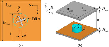
The design layout of the proposed DRA is shown in Fig. 1. It includes FR4 substrate (Lsub × Wsub × Hsub) of ɛrsub = 4.4 and tan δ = 0.02, with a running 50 Ω microstrip line (l × w) in the bottom side and a rotated cross-slot (p × q) in the top side ground plane. A cylindrical DR (h = d/2) of ɛrd = 10 and tan δ = 0.003 is placed at the center of the cross-slot. Another FR4 sheet (Lsup × Wsup × Hsup) of ɛrsub = 4.4 and tan δ = 0.004 is used as a superstrate above the DR with an air gap (a). The detailed design dimensions are given in Table 1. This proposed structure is designed using finite element electromagnetic solver Ansoft HFSS v13.0 [19].
Configuration of the proposed dielectric resonator antenna. (a) Top-view without superstrate and without DRA (blue circle marks the location of DRA), (b) 3D-view.

Parameter values of the proposed antenna

Design and development
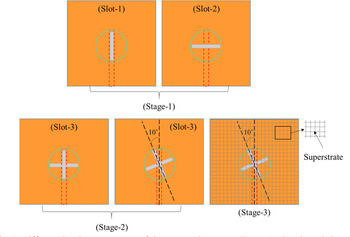
The objective of the proposed work is to ensure dual-band circular polarization with an improved gain performance by means of single feed and superstrate. The proposed antenna is developed in three stages to achieve dual band (stage 1), circular polarization (stage 2), and enhanced gain (stage 3) as illustrated in Fig. 2. These stages are discussed in detail below.
Different development stages of the proposed antenna (stage 1: plus-shaped slot, stage 2: 10° rotated cross-slot, stage 3: loaded with superstrate).

Stage 1: linearly polarized standalone DRA
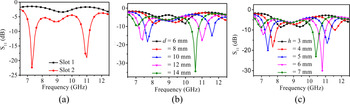
In the proposed antenna, aperture coupling method is used to excite the DR. In the initial step, a rectangular slot (p × q = 0.5 mm × 6 mm) is created in the ground plane which is parallel to the length of microstrip feed line in the bottom side (see slot 1 in Fig. 2). A cylindrical DR (d = 6 mm, h = 5 mm) is placed at the center of the slot. As seen in Fig. 3(a), this configuration does not excite resonance in the antenna. Next, the slot is rotated 90° (orthogonal to feed line), see slot 2 in Fig. 2. The arrangement produces sharp dual-resonances at 7.4 and 11 GHz and is shown in Fig. 3(a). Then using slot 2, the DR dimensions (i.e. diameter d and height h) are studied and their effects on return loss and resonance are illustrated in Figs 3(b) and 3(c), respectively. To balance performance and physical size, diameter (d) and height (h) are fixed at 10 and 5 mm, respectively. In this configuration, the antenna resonates at 7.4 and 11.2 GHz. The gain values at these resonance points are recorded as 5.5 and 4.9 dBi, respectively. At both the frequencies, the antenna operates in linear polarization (LP) mode.
S 11 response of stage 1, for different (a) slot types, (b) DR diameter, (c) DR height.

Stage 2: actualization of circular polarization using cross-slot
In this stage, circular polarization is ensured in the existing geometry without using any additional feed. To achieve this, the slot lines are engineered carefully to create out-of-phase excitation and obtain AR below 3 dB without disturbing the dual-band performance.
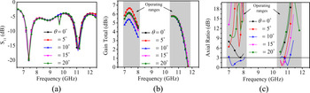
In the first attempt, slot 1 (i.e. parallel to feed line) and slot 2 (i.e. perpendicular to feed line) are combined and form a plus-shaped (+) slot (slot 3). This slot 3 is symmetric along the feed line as shown in Fig. 2. The corresponding results are depicted in Figs 4(a) and 4(b) (see at θ = 0°). It is seen that the dual-band resonances are almost intact with gain values 7.21 and 5.59 dBi at the lower and upper bands, respectively. It is obvious, as the slot is symmetric to the feed line and ground, this configuration delivers linearly polarized waves.
Comparison of results in stage 2 with different slot angles (θ), (a) S 11, (b) gain total, (c) axial ratio.

In the second attempt, the plus-shaped slot is rotated in anti-clockwise direction xy-plane (now it looks like cross-shaped). Due to the rotation, the center line of the slot forms an angle with the feed line and the edge of the ground plane. As a result, the symmetry between the slot and feed line is broken and orthogonal components may have a phase difference, and therefore, create out-of-phase excitation. In the next attempt, the angle of rotation, i.e. θ is swept between θ = 0° and θ = 20° at a step of θ = 5° to attain a suitable phase difference so as to achieve good AR. The corresponding AR responses are plotted in Fig. 4(c). It is seen that at θ = 10° in both the lower and upper bands, the AR is below 3 dB, which ensures circular polarization. This construes that θ = 10° is the key factor for generating/establishing better orthogonal phase difference (therefore, circular polarization) in both the bands. At θ = 10°, minimum AR values are recorded at 0.8 and 0.5 dB (Fig. 4(c)), with gain values of 5.22 and 5.59 dBi, respectively (Fig. 4(b)).
Stage 3: enhancement of gain using superstrate
Superstrate technique is a prominent method for gain and directivity enhancement of any antenna. It works on the principle of multiple reflection [Reference Munk20]. When the superstrate is placed above the radiator, not all radiating waves are able to penetrate the transparent superstrate; as a result, they are reflected from the superstrate surface and incident on the ground plane and again reflected back [Reference Swartwout5]. In the second cycle, the reflected waves from the ground plane are combined with the fresh radiating waves which eventually form comparatively strengthened waves and move toward the superstrate [Reference Swartwout5, Reference Munk20]. When these strengthened waves strike on the superstrate, some waves penetrate it and the others are reflected back. The process continues. It is known as multiple reflection (as shown in Fig. 5). Because some extremely strengthened waves penetrate/transmit through superstrate, high gain/directivity is achieved [Reference Munk20].
Sketch of multiple reflection mechanism.

In this context, an FR4 dielectric superstrate (Lsup × Wsup × hsup) is introduced above the DR to enhance the gain of the antenna. Its position above the ground plane can be computed as [Reference Dutta, Guha, Kumar and Antar18] to allow possible reflection:

where c = speed of light in free space, f 0 = first/lower resonant frequency of standalone DRA, i.e. 7.4 GHz.
When the superstrate is placed above the DR as well as the ground plane, it closely forms a Fabry–Perot cavity [Reference Dutta, Guha, Kumar and Antar18]. The effective permittivity of the cavity due to the presence of DR and air inside the cavity (between two walls, i.e. ground plane and superstrate) can be determined as [Reference Dutta, Guha, Kumar and Antar18]:

where h is the height of the DR, a is air gap, and dielectric constant is ɛr = 10. ɛreff is computed as 1.13 using equation (2).
The corresponding effective superstrate air gap (aeff) can be updated as [Reference Dutta, Guha, Kumar and Antar18]:

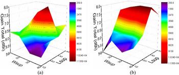
As per the theoretical prediction, the superstrate is placed at aeff = 22.6 mm distance from the ground plane surface. After the placement, the dimension of the superstrate is further studied to achieve the desired gain. Both superstrate length (Lsup) and width (Wsup) are simultaneously varied between 10 and 40 mm with a step size of 10 mm. The corresponding gain responses for both the upper and lower bands are plotted in Figs 6(a) and 6(b), respectively. It shows that letting Lsup = 30 mm and Wsup = 30 mm produces maximum gain values of 8.06 and 8.07 dBi at the lower and upper bands, respectively. It is also observed that S 11 and AR are not affected by the superstrate dimension and the respective results are not included for brevity.
Gain total variation in stage 3 for different combinations of superstrate dimensions, (a) in lower band, (b) in upper band.

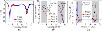
Finally, the antenna performance in different stages is compared in Fig. 7. This clearly signifies that the impact of different stages on S 11 is negligible (Fig. 7(a)). However, it has a significant effect on gain and circular polarization (AR). As shown in Fig. 7(b), for stage 3, peak gains are recorded as 8.06 and 8.07 dBi in the upper and lower bands, respectively, followed by AR of 1.45 and 1.55 dB (Fig. 7(c)). Hence, stage 3 geometry is considered as the final design and taken for fabrication. The comparative results of all stages are summarized in Table 2.
Performances comparison of all stages, (a) S 11, (b) gain total, (c) axial ratio.

Summary of all stages and comparison of simulated and measured results

Based on the above study, straightforward design guidelines are suggested below:
1. Consider a cylindrical DR. Take ɛrd as per availability (preferably 10).
2. To achieve dual-band performance, the DR should be coupled through a rectangular slot, i.e. slot 2 which is perpendicular to feed line. Initial parameters may be taken as, l = 0.49λ 0, p = 0.14λ 0, and q = 0.012λ 0.
a. Feed line and slot dimension may be adjusted for proper matching.
b. Adjust DR radius r and height h to reach desired operating frequencies.
3. To achieve circular polarization:
a. Design a plus-shaped slot, i.e. slot 3, as shown in Fig. 2.
b. Rotate slot 3 in anti-clockwise direction by an angle θ = 10° to achieve AR < 3 dB.
c. The rotation angle θ may need further adjustment for AR < 3 dB at other frequencies other than mentioned in the paper.
4. To enhance the gain of the antenna place, a superstrate (lsup = wsup = 0.74 λ 0) and its position (a) can be computed using equations (1)–(3).
5. The dimension of the superstrate may need adjustment if the antenna operates at any frequencies other than mentioned in the paper.
Measurement and verification
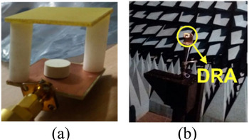
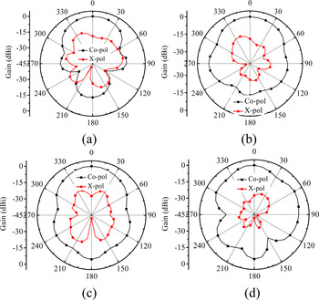
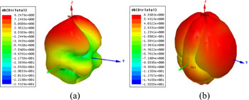
The fabricated prototype is depicted in Fig. 8. The cross-shaped slot and feed line are etched on the respective sides of the FR4 sheet using a photolithographic etching process. The proposed DR is tailored out from an Eccostock HiK (ɛrd = 10 and tan δ = 0.003) cylindrical rod and is placed on the cross-slot. An FR4 sheet with copper stripped on both sides is placed at an appropriate height above the ground plane with the help of two Teflon rods (ɛr = 2.1). Adhesive gum is used carefully to place the DR and Teflon rods. The antenna is characterized using an automatic anechoic chamber (size 7 m × 4 m × 3 m) and VNA (Anritsu Microwave Site Master-S820E). During measurement, the antenna is kept in Fraunhofer (far-field) region from the transmitting horn antenna. The antenna is rotated using a motor in both E-plane and H-plane to measure the received power from a different angle. The simulated and measured S 11 are shown in Fig. 9(a). During measurement, the antenna operates between 7.2 and 7.6 GHz in the lower band and 10.0 and 10.6 GHz in the upper band, which are slightly different from the simulation. Figure 9(b) shows that the antenna attains gain ~8 dBi in the lower band and ~7.8 dBi in the upper band, i.e. minor mismatch with the simulation. Similarly, Fig. 9(c) shows the AR results, i.e. AR~2.2 dB in the lower band and AR ~2.35 dB in the higher band. The measured radiation patterns at 7.4 and 11.2 GHz are depicted in Fig. 10. The antenna maintains minimum co-pol to cross-pol difference of 20 dB in all directions. However, at 7.4 GHz (in E-plane), there is slight overlapping between the co-pol and cross-pol at some angle which is usually acceptable. The simulated 3D polar plots at both the resonating frequencies are shown in Fig. 11. In either case, as per the color scale, the red color signifies the highest value of radiation. It can be construed that at 7.4 GHz, the antenna produces maximum radiation in broad side direction with comparatively lower radiation in other directions. It is seen at 11.2 GHz, the antenna radiation is good almost in all directions. Comparing the radiation plot with the color scale, it can be construed that the results are good and acceptable.
Fabricated prototype, (a) 3D view, (b) set up inside the anechoic chamber.

Comparison of simulated and measured results, (a) S 11, (b) gain total, (c) axial ratio.

Measured radiation pattern, (a) E-plane, (b) H-plane at 7.4 GHz, and (c) E-plane, (d) H-plane at 11.2 GHz.

3D Polar plot, (a) at 7.4 GHz, (b) at 11.2 GHz.

The performance comparison of the simulated and measured model is shown in Table 2. The observed variation between the simulated and measured results may be attributed to the unconsidered soldering deposits, Teflon rod for holding the superstrate, and small/invisible air gap between the DR and the ground plane sheet.
The proposed antenna performance is also compared with other available literature and the results are shown in Table 3. The proposed antenna ensures circular polarization in dual-band with good gain values. In comparison to others, the size of the proposed antenna is small. The lower band of the proposed antenna can be used for satellite downlink (space-to-earth) and the upper band can be used for fixed satellite service applications.
Comparison of the proposed antenna with available literature

CP, circular polarization.
a Single band with dual resonance.
Conclusion
A single-fed superstrate loaded cylindrical DRA is investigated for dual-band circular polarization with enhanced gain. The proposed DR is coupled through a 10° rotated cross-slot to generate out-of-phase excitation and ensure circular polarization (AR below 3 dB) at 7.4 and 11.2 GHz. A dielectric superstrate is placed appropriately above the antenna to create multiple reflection and to improve the gain up to 8.06 and 8.07 dBi, respectively. The antenna design is simple and its performance is suitable for X-band satellite communications. In future research, this antenna performance may be further improved by employing frequency-selective surface in the superstrate.
Acknowledgements
This research was partially supported by the National Natural Science Foundation of China Grant 62071211 and University Key Laboratory of Advanced Wireless Communications of Guangdong Province, Southern University of Science and Technology, Shenzhen, China. .
 Sounik Kiran Kumar Dash received his B.Tech degree in the stream of Electronics & Communication Engineering from the Centurion University of Technology and Management, Bhubaneswar, India in 2013; M.Tech degree with specialization of Communication System Engineering from KIIT University, Bhubaneswar, India in 2015; and Ph.D. from the National Institute of Technology (NIT) Silchar, Assam, India in 2018. In 2019, he was working as an Assistant Professor at CHRIST (Deemed to be University), Bengaluru, India. At present, he is working as a Post-Doctoral Research Fellow at the Southern University of Science and Technology (SUSTech), Shenzhen, China. His current research interests include dielectric resonator antennas (DRAs), SIW backed antennas, RF energy harvesting, UWB antennas, MIMO antennas, reconfigurable antennas, numerical methods in electromagnetics, and neural networks. He has authored or co-authored over 30 research articles in refereed journals (such as IEEE, IET, Wiley, etc.) and international conference/symposium proceedings (such as URSI GASS, EuMW, AEMC, etc.) of repute. He is appointed as the Advisory Editor for Wiley Engineering Reports. He is an active reviewer of several refereed journals of international repute, i.e. IEEE Transactions on Antennas and Propagation, IEEE Consumer Electronics Magazine, IEEE Access, Wiley International Journal of RF and Microwave Computer-Aided Engineering, and so on. He has received several grants such as Special Student Grant from European Microwave Association (EuMA), Belgium, Foreign Travel Grant from the Council of Scientific & Industrial Research (CSIR), Govt. of India for attending various international events. He is an active member of IEEE APS/SPS/EDS (USA), URSI (Belgium), and IAENG (Hong Kong).
 Qingsha S. Cheng received the B.Eng. and M.Eng. degrees from Chongqing University, China, in 1995 and 1998, respectively. He received his Ph.D. at McMaster University, Canada, in 2004. In 1998, he was with the Department of Computer Science and Technology, Peking University, China. In 2004, he became a postdoctoral fellow and then a research engineer in 2007, both with the Department of Electrical and Computer Engineering, McMaster University. In 2014, he joined the Southern University of Science and Technology (SUSTech), Shenzhen, China as an Assistant Professor in the Department of Electrical and Electronic Engineering. His research interests include design and modeling of microwave circuits, surrogate modeling and optimization, multi-objective optimization, computer-aided design and tuning, post-production tuning techniques, and novel materials and fabrication technologies. He has authored or co-authored around 150 publications in technical book chapters, refereed international technical journals, refereed international conference proceedings and international workshops.
 Taimoor Khan is presently an Assistant Professor in the Department of Electronics and Communication Engineering at the National Institute of Technology Silchar, India where he serves as a full-time faculty member since 2014. During September–December 2016, he has worked as a Visiting Assistant Professor in Telecommunication Field of Study at the Asian Institute of Technology, Bangkok, Thailand under Secondment Programme of Ministry of HRD, Govt. of India. Prior to joining NIT Silchar, he served several organizations such as Delhi Technological University (Formerly Delhi College of Engineering), Govt. of NCT of Delhi, Delhi, India as an Assistant Professor for more than 2 years; Netaji Subhas Institute of Technology Patna, India as an Associate Professor and Head of the Department for one and a half year; and Shobhit Institute of Engineering and Technology, Meerut, Uttar Pradesh, India as a Lab Instructor, Lecturer, and Assistant Professor for more than 9 years. Dr. Khan had been awarded his Ph.D. degree in Electronics and Communication Engineering from the National Institute of Technology Patna, India in the year 2014. His active research interest includes communication engineering, printed microwave circuits, electromagnetic bandgap structures, computational electromagnetics, and artificial intelligence paradigms in electromagnetics. He has published over 65 research papers in international journals of repute such as IEEE, IET, Wiley, Taylor and Frances, Cambridge University, Progress in Electromagnetic Research, etc., as well as in international/national conference proceedings including URSI GASS, European Microwave Week, AEMC, APACE, ISMOT, etc. Dr. Khan is executing three funded research projects including one international collaborative project with Queen's University Canada.