I. INTRODUCTION
Mg and its alloys are promising implant materials in orthopedic applications due to their attractive mechanical and biological performances: Reference Staiger, Pietak, Huadmai and Dias1–Reference Witte, Kaese, Haferkamp and Switzer4 (i) the density, elastic modulus, and yield strength of Mg-based materials are much closer to those of natural bone, which can greatly reduce the stress shielding effect; (ii) Mg-based materials are easy to be degraded in the body fluid environment by corrosion, and Mg2+ can catalyze new bone tissue growth and bone binding with implants, which make the patients free from a second operation. However, Mg and its alloys have a high degradation rate in the human body fluid, which are possible to lose the mechanical integrity before the tissue haled due to the rapid corrosion. Reference Staiger, Pietak, Huadmai and Dias1
To slow down the biodegradation rate of Mg-based materials and improve their mechanical properties, it is necessary to employ a proper treatment technique to improve the surface properties of materials. MAO is a convenient and promising approach to form ceramic coatings on the surface of light metals such as Ti, Al, and Mg. It is an electrochemical technique for the formation of an anodic ceramic layer by spark/arc micro discharges in a suitable electrolyte. Reference Yerokhin, Nie, Leyland, Matthews and Dowey5,Reference Gupta, Tenhundfeld, Daigle and Ryabkov6 After the MAO process, the surface properties, such as corrosion resistance, wear resistance, hardness, and adhesion to substrate can be considerably improved. Reference Rama Krishna, Somajaju and Sundararajan7–Reference Yerokhin, Nie, Leyland and Matthews9 However, it is undeniable that the ordinary MAO coating still has some shortcomings, such as micro-pores, micro-cracks, and lack of biological activity. Reference Zhao, Cui, Wang and Bu10–Reference Xin, Liu, Zhang, Tang, Tian and Chu12 Because the composition of MAO coating stems from the substrate and the electrolyte, some special elements can be incorporated into the MAO coating to further improve the surface properties of materials. Zirconia has excellent chemical and thermal stability, wear resistance, high strength and fracture toughness, and bio-inertness. Reference Mu and Han13 In addition, the rare earth oxides with the higher dielectric parameter also have a beneficial effect on the micro-structural stability and corrosion resistance. Reference Cai, Cao, Chang, Zheng, Zhang and Cao14 Some researchers have confirmed that the addition of zirconium oxide (ZrO2), titanium oxide (TiO2), aluminum oxide (Ai2O3), and rare earth oxide nanoparticles to MAO coating is beneficial to improve its functionality. Reference Mandelli, Bestetti, Da Forno, Lecis, Trasatti and Trueba15–Reference Lim, Ryu and Hong23 These studies showed that TiO2, ZrO2, and Al2O3 nanoparticles could improve the adhesion and hardness of the MAO coating, and decrease the corrosion rate of Mg alloys. The cerium oxides (CeO2) and ZrO2 particles could prevent crack from propagating and not largely breaking the balance between the oxidation and fusing/recrystallization.
As implant materials for Mg and its alloys, besides improving the mechanical properties and the biodegradation rate, the bioactivity and the biocompatibility should also be considered. HA [Ca10(PO4)6(OH)2] is a major inorganic component of natural bone, it can promote more rapid fixation and stronger bonding between the host and the implant. Reference Burg, Porter and Kellam24–Reference Kumar and Wang26 Unfortunately, the mechanical strength of HA is too poor to be used in load-bearing applications, it is limited in the clinical orthopedic applications. Reference De With, Van Dijck, Hattu and Prijs27 To improve both the mechanical and biological properties, it is necessary for taking appropriate treatment methods to prepare a HA layer on the substrate of metallic implants. An appropriate implant material should be a bio-ceramic composite formed by a bioactive ceramic such as HA and a bio-inert phase (ZrO2). Reference Samanipour, Bayati, Zargar, Golestani-Fard, Troczynski and Taheri22 Electrophoretic deposition (EPD) is a simple and inexpensive technique for the development of ceramic coatings, in which coatings are formed on the electrode by migration of charged ceramic particles under the influence of an electric field. Reference Sreekanth and Rameshbabu28 It is well known that the surface properties of MAO coating mostly depend on the inner barrier layer and the outer porous layer. Reference Yerokhin, Nie, Leyland, Matthews and Dowey5 A promising approach that used EPD as a post-treatment process introduces HA nanoparticles into the porous layer of MAO coating for improving the bioactivity of the coating. Some studies Reference Kim, Kim, Kim, Koh, Kim and Jang29,Reference Nie, Leyland and Matthews30 demonstrated that HA particles added into micro-arc oxidized titanium (Ti) alloys would improve the alloys’ bioactivity and mechanical integrity.
In this study, MAO and EPD processes were used to fabricate a bio-composite ceramic coating on ZK60 Mg alloy. MAO coatings were prepared in an alkaline electrolyte with and without the addition of nanoparticles (CeO2 and ZrO2), and EPD as post-treatment produced HA layer on the surface of MAO coating. The composition, microstructure, adhesion, wear resistance, and corrosion resistance of these coatings were investigated, and their formation mechanism is discussed.
II. EXPERIMENTAL
A. Specimens and electrolyte solutions
The material in this investigation is an extruded ZK60 Mg alloy. The chemical composition of the material is 5% Zn, 0.64% Zr, and Mg as balance. Samples of MAO process were machined to the dimensions of 40 × 22 × 2 mm. Before MAO treatment, the surface of the samples was polished using silicon carbide papers with grit numbers ranging from 280 to 1200. Subsequently, the sample was ultrasonically degreased in ethanol for 10 min, cleaned with deionized water, and then dried in ambient air.
The compositions of the MAO electrolyte and EPD suspension are shown in Table I. The MAO electrolyte with a pH of 12 was adjusted by using NaOH solution. The electrolyte for the MAO process is an alkaline silicate solution consisting of 17.5 g/L Na2SiO3·9H2O and 10 g/L NaF2, the prepared samples are named as 60-M1. The samples prepared by the addition of 5 g/L ZrO2 nanoparticles (20–50 nm) and 1.5 g/L CeO2 nanoparticle (50–100 nm) powder are named as 60-M2. MAO treated time was 10 and 20 min, respectively. The suspension for EPD post-treatment is a phosphate salt electrolyte consisting of 10 g/L Na3PO4, 3 g/L HA nanoparticles (50–100 nm) powder, and 3 mL/L ethylene glycol, the prepared samples are named as 60-MD.
Composition of the MAO electrolyte and EPD suspension.

B. MAO and EPD processes
A MAO system which consists of a stainless steel container, cooling and stirring systems was performed with a bidirectional pulse current power supply (30 kW). In the MAO process, the Mg alloy sample and the stainless steel container were used as the anode and the cathode, respectively. The test was carried out at a constant current density of 10 A/dm2 and duty cycle of 37.5% for 20 min, the temperature of the electrolyte was kept at 30 °C by a cooling system. After MAO treatment, the samples were ultrasonically cleaned in deionized water for 10 min and dried at room temperature. For EPD treatment, the sample was used as anode, which was immersed in HA suspension and connected with a D.C. voltage of around 380 V for 10 min.
C. Coating characterization
The surface morphology of the coated samples was observed by scanning electron microscopy (SEM; JSM-6510, JEOL Ltd., Tokyo, Japan). The phase composition of the coatings was identified by an X-ray diffractometer (XRD; D/Max-2500v/pc, Rigaku Corporation, Tokyo, Japan) using Cu Kα radiation at the 10–80° (in 2θ) and steps of 0.02°.
D. Scratch and wear tests
The adhesion of coatings was investigated using a scratch tester. A diamond stylus is drawn across a surface with increasing normal load at a constant speed of 1.25 mm/min until defined failures occur at a certain critical load (L c). The scratch hardness was calculated according to ASTMG-171-03. 31 Dry wear tests were conducted using a pin-on-disc tribometer at room temperature. All the wear tests were performed with 4 mm diameter SiC ball in sliding contact with a load of 2 N at a speed of 200 rpm for 60 min. After the wear test, the wear track was measured by SEM. The values of L c were detected with SEM by examination of the scratch track.
E. Electrochemical tests
The corrosion behaviors of the coatings were investigated by potentiodynamic polarization curves and electrochemical impedance spectroscopy (EIS) measurement in SBF solution at 36.5 ± 0.5 °C. The SBF solution was prepared according to the ISO10993-15 standard 32 as shown in Table II. Electrochemical tests were carried out using a standard three-electrode cell with Pt as a counter electrode, saturated calomel electrode (SCE) as a reference, and the coated sample with exposed area of 1 cm2 as the working electrode. The ratio of the test solution volume (mL) to the specimen surface area (cm2) was 300 mL/cm2. All the measurements in this study at a scanning rate of 10 mV/s were taken after stabilization of the open circuit potential (OCP), i.e., 30 min after immersion of the electrode in SBF solution which was stirred during the entire experiment, the change range of OCP remained within ±5 mV. EIS curves were collected in a range of 0.01 Hz to 100 kHz with AC voltage amplitude of 10 mV, and the measurements were made after 0.5, 12, 120, 480, and 720 h of immersion in the SBF solution. All potentiodynamic polarization and EIS data were analyzed using the CorShow and ZSimpWin software, respectively.
Composition of simulated body fluid (SBF, pH7.4).

III. RESULTS AND DISCUSSION
A. Morphology of coatings
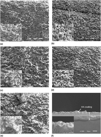
Figure 1 shows the surface micrographs of coatings at different process conditions. It can be seen that there are some micro-pores which are separated and uniformly distributed on the surfaces of MAO treated coatings, and the size of the micro-pore is generally 1–3 μm in diameter. Micro-pores are formed by molten oxide and gas bubbles thrown out of micro-arc discharge channels during the MAO process. Reference Yerokhin, Nie, Leyland, Matthews and Dowey5,Reference Gupta, Tenhundfeld, Daigle and Ryabkov6 For the MAO coatings with CeO2/ZrO2-free, the coating of the sample 60-M1-20 [Fig. 1(c)] is not much uniform and has some micro-cracks (indicated by arrows) compared with the sample 60-M1-10 [Fig. 1(a)]. The micro-cracks resulted from thermal stress due to rapid solidification of molten oxide in the relatively cool electrolyte. Reference Guo and An33 It is also noticed that as the MAO treated time increased from 10 to 20 min, the porosity is decreasing while the diameter of the pores is apparently increasing, the diameter reaches about 3–5 μm. For the MAO coatings with CeO2/ZrO2-addition, some micro-pores in the surface of sample 60-M2-20 are filled with particles [as indicated by arrows in Fig. 1(d)] compared to the sample 60-M2-10 [Fig. 1(b)]. These fillers are associated with the additive ZrO2/CeO2 nanoparticles. Figures 1(e) and 1(f) show the surface and cross section micrographs of the CeO2/ZrO2-HA composite coating formed by MAO/EPD processes, respectively. It is found that the surface of sample 60-MD [Fig. 1(e)] is covered by some compounds and porosity is obviously reduced compared to the MAO treated samples. In addition, the cross section of the n-MAO/EPD composite coating is dense structure, and thickness of the coating reaches 18 μm [Fig. 1(f)]. The surface of the MAO coating has some micro-pores, it has become the land of HA nanoparticles. Therefore, it is speculated that the HA nanoparticles (50–100 nm) are drawn into the pores (3–5 μm) of the MAO coating and filled most of the existing pores, which decreased the porosity of the MAO/EPD composite coating.
Surface and cross section micrographs of coatings prepared by different process conditions: (a) 60-M1-10, (b) 60-M2-10, (c) 60-M1-20, (d) 60-M2-20, and (e and f) 60-MD.

B. Phase composition of coatings
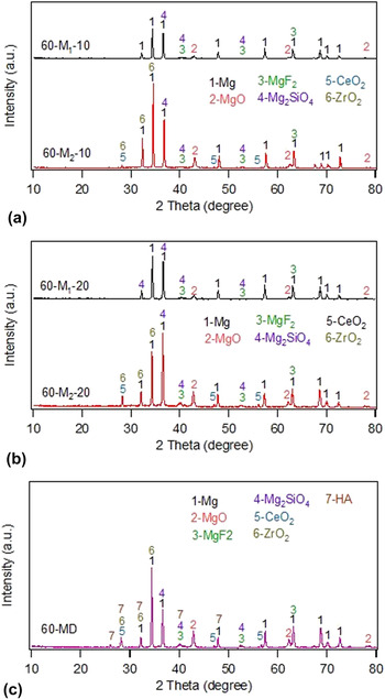
The XRD patterns of coatings at different process conditions are shown in Fig. 2. It is noticed that the primary peaks are similar to all the MAO coatings. As shown in Figs. 2(a) and 2(b), the main phase compositions of MAO coatings with CeO2/ZrO2-free (60-M1-10 and 60-M1-20) and CeO2/ZrO2-addition (60-M2-10 and 60-M2-20) are magnesium oxide (MgO), magnesium fluoride (MgF2), and magnesium silicate (Mg2SiO3). These results demonstrate that the SiO3 2−, F− ions, and O2 participated in the growth process of MAO coating, they react with the Mg2+ ion to form some phase compositions. In addition, the peaks of CeO2 and ZrO2 are detected on the surface of samples 60-M2-10 and 60-M2-20, it is revealed that a number of CeO2 and ZrO2 particles are incorporated into the MAO coating. Compared with Figs. 2(a) and 2(b), it is found that the peak values of those phases are increasing with MAO treated time increased from 10 to 20 min. It is indicated that additives can be fully integrated into the coating with MAO treated time prolonged. Figure 2(c) shows the XRD pattern of sample 60-MD. It is noticed that HA peaks existed in MAO/EPD composite coating except the above mentioned, which indicates that HA additives are deposited in the MAO coating after EPD post-treatment.
XRD patterns of the coatings prepared by different process conditions: (a) MAO, 10 min, (b) MAO, 20 min, and (c) MAO, 20 min/EPD, 10 min.

C. Adhesion and wear resistance
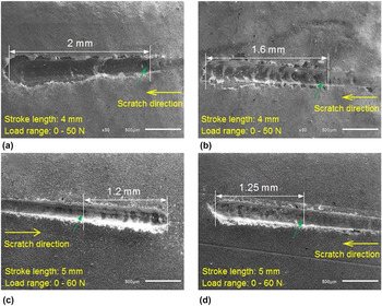
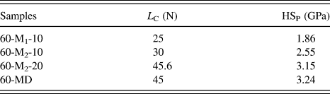
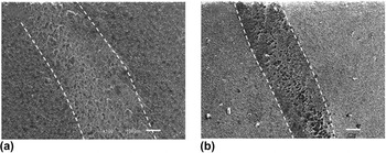
Figure 3 shows the SEM track images after scratch test for different treated coatings. Scratch length and load range also are marked in Fig. 3. When the total load reaches L c value, there are some black areas (indicated by green arrows) in the bottom of the grooves. It is indicated that the coating suffered from fracture due to plastic deformation and then the Mg alloy substrate is exposed. The existence of black area may be due to the oxide film formed on the surface of the Mg alloy. From critical load (L c) to the end of the loading, the scratch track became wider and black area is large. Critical load (L c) and scratch hardness (HSP) are presented in Table III. For the MAO coatings treated for 10 min, the critical loads of the MAO coating with CeO2/ZrO2-free [Fig. 3(a)] and with CeO2/ZrO2-addition [Fig. 3(b)] are L c = 25 N (60-M1-10) and L c = 30 N (60-M2-10), respectively. It is exhibited that the addition of CeO2/ZrO2 nanoparticles can improve the adhesion strength between the MAO coating and the substrate. For the MAO coatings with CeO2/ZrO2-addition, the coating critical load of sample 60-M2-20 [Fig. 3(c)] is greater than sample 60-M2-10 [Fig. 3(b)], the L c value reaches 45.6 N. It is indicated that the adhesion of the coating is further improved with the prolonging of MAO treatment time. After EPD post-treatment, the L c value of sample 60-MD is 45 N which is almost consistent with the 60-M2-20, whereas the scratch hardness (HSP) of the former is a little higher than that of the latter. Figure 4 exhibits the SEM micrographs of the wear tracks of samples 60-M2-20 and 60-MD. It can be seen that the wear track of sample 60-MD is narrower than that of sample 60-M2-20. After weighing with an electronic balance, the weight loss of the Mg alloy substrate is 2.250 × 10⁻³ g, the sample 60-M2-20 is 0.929 × 10⁻³ g, and the sample 60-MD is 0.686 × 10⁻³ g. The improvement of the wear resistance is due to the compact microstructure and the high hardness of the coating. Reference Liang, Wang, Hu and Hao34 As the above experimental results, the sample 60-MD shows high hardness and low weight loss as compared to the sample 60-M2-20. Therefore, CeO2/ZrO2-HA composite coating has good wear resistance compared to the MAO coating with CeO2/ZrO2-addition. The MAO coating is composed of a porous layer and a barrier layer. The barrier layer connect with Mg alloy substrate is compact and they exhibit a better bonding. In addition, homogenous HA crystals formed in the porous layer make the MAO coating become denser, which can further improve the adhesion. Reference Vangolu, Alsaran and Yildirim35 Thus, the increased adhesion makes the separation of the coating from the substrate become difficult and the wear resistance increase.
SEM images of scratch tracks for different treated coatings: (a) 60-M1-10, (b) 60-M2-10, (c) 60-M2-20, and (d) 60-MD.

Critical load (L C) and scratch hardness (HSP).

SEM images of scratch tracks for different treated coatings: (a) 60-M2-20 and (b) 60-MD.

D. Corrosion resistance
1. Potentiodynamic polarization curves
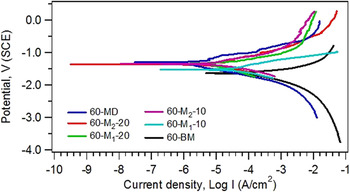
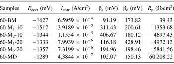
Figure 5 shows the potentiodynamic polarization curves of ZK60 Mg alloy substrate and different treated coatings in SBF at 36.5 ± 0.5 °C. The corrosion potential (E corr), corrosion current density (I corr), and the anodic/cathodic Tafel constants (βa, βc) are extracted directly from the potentiodynamic polarization curves by using the method of Tafel least square fitting. The polarization resistance (R p) can be obtained from the Stern–Geary equation Reference Duan, Yan and Wang36
 $${R_{\rm{p}}} = {{{\beta _{\rm{a}}}{\beta _{\rm{c}}}} \over {2.303{i_{{\rm{corr}}}}\left( {{\beta _{\rm{a}}} + {\beta _{\rm{c}}}} \right)}}.$$
Potentiodynamic polarization curves of different samples in SBF.

All the parameter values are listed in Table IV. Lower i corr, positive E corr, and higher R p indicate the coating provided with better corrosion resistance. Compared with the ZK60 Mg alloy substrate, R p of the samples with MAO coatings increases by 34–148 times, which indicates that the corrosion resistance of the Mg alloy has to be significantly improved by MAO treatment. For the samples treated for 10 min, E corr of the MAO coating with CeO2/ZrO2-addition (60-M2-10) shifted from 173 mV to the positive direction compared to the MAO coating with CeO2/ZrO2-free (60-M1-10), and R p is increased by about three times. For the samples treated for 20 min, the electrochemical parameters of samples 60-M1-20 and 60-M2-20 are slightly higher than that of 60-M2-10 as shown in Table IV. Among all the MAO treated samples, the coating of sample 60-M2-20 has better corrosion resistance. The above results indicate that the addition of CeO2/ZrO2 nanoparticles in the electrolyte played a role for improving the corrosion resistance of the coating. This can be attributed to the CeO2 and ZrO2 phases being propitious to improve the dense microstructures of the coatings, additional, ZrO2, CeO2, and MgF2 had higher chemical thermodynamic stability. Reference Mu and Han13,Reference Luo, Cai, Wei, Yu, He and Li21 After EPD post-treatment, E corr of the sample 60-MD shifted only 62 mV to the positive direction compared to the sample 60-M2-20, while both i corr and R p are one order lower than that of the sample 60-M2-20, which indicates that CeO2/ZrO2-HA composite coating has better corrosion resistance among all the treated samples.
Parameter values for different samples from potentiodynamic polarization test in SBF.

2. EIS measurements
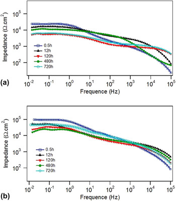
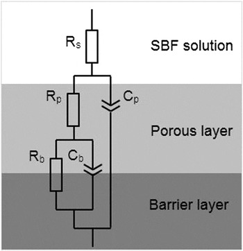
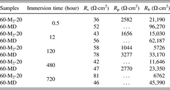
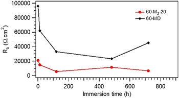
To further understand the corrosion behavior and the associated deterioration process of the CeO2/ZrO2 coating and CeO2/ZrO2-HA composite coating, EIS measurements are used in samples 60-M2-20 and 60-MD. The Bode plots of electrochemical impedance of samples produced at various pulse frequencies after immersing in the SBF are presented in Fig. 6. The equivalent circuit used for fitting impedance data of MAO coating is reported in Fig. 7. In the equivalent circuit, R s is the solution resistance, R p is the porous region resistance of the MAO coating paralleled with constant phase element C p, R b is the barrier layer resistance of the MAO coating in parallel with C b. The corresponding EIS data are presented in Table V. It can be seen that the R s value is very low for two kinds of coated samples because the SBF has a good conductivity. The R p value decreases with increasing immersion time because the porous layer is dissolved by corrosive SBF. In addition, the R b value is always larger than the R p value during immersion time, indicating the barrier layer plays the most important role in the corrosion protection of the coating. Therefore, the barrier layer resistance is the dominating parameter for electrochemical performance of the MAO coated samples. A sample with a higher R b value has good corrosion resistance. Figure 8 shows the R b value as a function of immersion time. It is found that the R b value of sample 60-MD is much higher than that of sample 60-M2-20 during immersion time. It is concluded that the HA nanoparticles deposited on the surface of MAO coating help to provide better anticorrosion property. As a result, the corrosion resistance of CeO2/ZrO2-HA composite coating is the best.
Bode plots of electrochemical impedance of samples after different immersion periods in SBF: (a) 60-M2-20 and (b) 60-MD.

Equivalent circuit for fitting impedance data of MAO coating.

EIS data for samples 60-M2-20 and 60-MD after immersion in SBF.

Barrier layer resistance R b of samples 60-M2-20 and 60-MD as a function of immersion.

E. Formation mechanism of coating
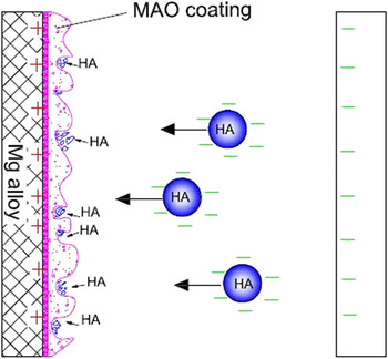
The growth models of the MAO/EPD bio-ceramic composite coating are used to explain the formation mechanism of the coating. The MAO process can be compartmentalized into two stages: (i) anodization and (ii) micro-arc oxidization. Figure 9 shows the schematic diagram of the EPD process.
Schematic diagram of HA particles deposited on the MAO coating.

At the initial stage, the voltage is below the breakdown value, the substrate is dissolved first, partial anions (F− and SiO3 2− ions) in the electrolyte and oxygen (O2) are transferred at the surface of the Mg alloy. Oxygen gas results from the oxidation of H2O molecules or OH− ions adsorbed on the anode surface according to the following reactions: Reference Guo, An, Xu and Huo37
 $$\eqalignb{ & 4{\rm{O}}{{\rm{H}}^ - } \to {{\rm{O}}_2} + 2{{\rm{H}}_2}{\rm{O}} + 4{\rm{e}} \cr & {\rm{or}} \cr & 2{{\rm{H}}_2}{\rm{O}} \to {{\rm{O}}_2} + 4{{\rm{H}}^ - } + 4{\rm{e}}{\rm{\hskip 10pt.}} \cr}$$
On the one hand, the substrate is dissolved first and a thin passive film is formed on the surface of the sample according to the following reaction:
 $$2{\rm{Mg}} + {{\rm{O}}_2} = 2{\rm{MgO}}{\rm{\hskip 10pt.}}$$
On the other hand, the colloidal particles (ZrO2 and CeO2) surrounded by the OH− ions are attracted to the anode and deposited on the surface of the oxide film.
When the voltage exceeded breakdown voltage, some weak parts of the anodic oxide film are broken down, and a large number of dispersed discharge channels are formed. The plasma in the discharge channel can reach high temperature and high pressure in a short time, and anions (OH−, F−, SiO2 3−) are driven by electric field to the anode where they combine with positively charged Mg2+ ions and formed compounds, as the following reactions:
 $${\rm{Mg}} = {\rm{M}}{{\rm{g}}^{2 + }} + 2{{\rm{e}}^ - }\hskip 10pt,$$
 $$2{{\rm{F}}^ - } + {\rm{M}}{{\rm{g}}^{2 + }} = {\rm{Mg}}{{\rm{F}}_2}\hskip 10pt,$$
 $$2{\rm{M}}{{\rm{g}}^{2 + }} + {\rm{Si}}{{\rm{O}}_3}^{2 - } + 2{\rm{O}}{{\rm{H}}^ - } = {\rm{M}}{{\rm{g}}_2}{\rm{Si}}{{\rm{O}}_4} + {{\rm{H}}_2}{\rm{O\hskip 10pt,}}$$
 $${{\rm{O}}^{2 - }} + {\rm{M}}{{\rm{g}}^{2 + }} = {\rm{MgO}}{\rm{\hskip 10pt.}}$$
The molten compounds are sprayed onto the oxide film/electrolyte interface through the discharge channel, and the pores are surrounded by molten oxide that is rapidly solidified by the surround electrolyte, an anodic oxide film is formed in the sparking zone. In addition, negatively charged ZrO2/CeO2 particles are drawn toward the anode by the electric field between the poles of the electrochemical cell; subsequently, they are drawn inside the pores and implanted in the growing layer. In this stage, the thickness of the anodic oxide film deposited by compounds is very thin because the development speed of film formation may be slower than the dissolution speed. Metal molten compounds and ZrO2/CeO2 phases mentioned above are detected by the XRD technique (Fig. 2).
With MAO treated time prolonged, the relatively thin part of the newly formed anodic oxide film is temporarily melted and molten compounds are erupted from the film surface along small discharge channels; thus the porous structure is formed once the melted coating is cooled down by the electrolyte. Reference Zhang and Zhang38,Reference Xue, Deng, Lai, Chen and Am39 In this manner, the coating continuously grew along outward and lateral directions, and the coating gradually increased in thickness along the two directions. When the coating is thick enough, more energy is needed to break the thicker coating. With micro-arc oxidization processed, the working voltage gradually increases and sparks become large, which leads the coating to grow up in a non-uniform pattern. Finally, a ceramic-like coating is formed on the surface of the sample, which comprises an outer porous layer and an inner barrier layer.
In the EPD process, a certain magnitude of voltage is applied between the cathode and the anode, and an electric field is formed between the poles. The suspension containing HA is alkaline, which makes HA particles dispersed in the electrolyte having a negative charge. Reference Kim, Kim, Kim, Koh, Kim and Jang29 Therefore, under the influence of these two factors, the negatively charged HA particles move toward the positively charged surface of the Mg substrate under an external electric field and coagulate into pores of MAO coatings containing ZrO2/CeO2, and then a bioactive ZrO2/CeO2-HA composite coating forms on the Mg alloy substrate (Fig. 9).
Combined with the experimental results above, the prepared ZrO2/CeO2-HA composite coating has the following advantages. (i) The MAO ceramic coating containing ZrO2/CeO2 closely combines with the Mg alloy substrate, which is helpful to improve the adhesion, wear resistance, and corrosion resistance of the substrate. (ii) EPD do not cause HA phase transformation; HA layers with high purity have a potential bioactivity due to their chemical and biological similarity to human bone tissues, which is helpful for the combination of the implant and the bone tissue. The HA-incorporated ZrO2/CeO2 coating shows good corrosion resistance too. (iii) There is a transition layer between the HA layer and the MAO bottom layer. This transition layer avoided the stress concentration in the coating, which is conducive to retain the stability of the ZrO2/CeO2-HA composite coating in the body environment. Therefore, the Mg alloy with ZrO2/CeO2-HA composite coating is expected to be used as an implant material, which needed to further be evaluated in in vivo experiments.
IV. CONCLUSIONS
This paper verifies the possibility and effectiveness of MAO/EPD composite modification technology for production of a CeO2/ZrO2-HA composite coating on the surface of Mg alloy. First, the MAO coatings are produced in an alkaline electrolyte with the addition of CeO2 and ZrO2 nanoparticles. The MAO coating with CeO2/ZrO2-addition shows good mechanical properties compared to the MAO coating with CeO2/ZrO2-free, including wear resistance, adhesive strength, and hardness. Subsequently, a bioactive HA layer is deposited on the surface of the MAO coating with CeO2/ZrO2-addition by the EPD process. It is shown that the CeO2/ZrO2-HA composite coating presents a more favorable corrosion resistance in SBF solution compared with the MAO coating with and without the addition of CeO2/ZrO2 nanoparticles. MAO/EPD composite modification technology is a potential treatment method for improving the surface function of Mg-based biomaterials.
ACKNOWLEDGMENTS
The authors gratefully acknowledge the project sponsored by National Natural Science Foundation of China (No. 51275472), Public Technology Application Research Project of Science Technology Department of Zhejiang Province (No. 2012C21101) and Natural Science Foundation of Zhejiang Province (No. LY12E05024).