I. INTRODUCTION
The development of advanced materials for high-end applications is driven by continuous progress in the synthesis and control of the materials microstructure on submicrometer and nanometer scales. Several pioneering studies have shown that, when confined to submicrometer dimensions, many materials exhibit unexpected and useful properties different from their macroscale behavior.Reference Arzt, Dehm, Gumbsch, Kraft and Weiss7 As an example, nanostructured bulk metals and thin film structures may exhibit extraordinary strength and fatigue resistance. Even for traditional materials, the general trend toward miniaturization of components and systems makes predictive modeling of their mechanical performance on the micro- and nanoscale an engineering problem of growing importance, because components of submicrometer size behave differently from their macroscopic counterparts. The challenge of developing predictive models for the size-dependent mechanical response of materials on small scales has led to an increased effort on developing dislocation-based continuum theories of plasticity. Although discrete dislocation dynamics (DDD) simulations (e.g., Refs. 5, 10, 15, 32, 35, 46, 47, 48) provide an alternative approach to continuum models, DDD cannot be easily incorporated into the engineering “toolbox” for component design and assessment, because there still exists no standard approach for simulating systems with general geometries and boundary conditions (BCs). In the context of continuum dislocation dynamics, on the other hand, DDD simulations can play an important role because they provide complete information about dislocation microstructures and distortion fields and can therefore be used for benchmarking the performance of different modeling approaches.
In Sec. II, we give an overview of dislocation-based modeling of plasticity with an emphasis on continuum methods. We discuss some shortcomings of previous approaches and present in Sec. III the Continuum Dislocation Dynamics (CDD) theory, which resolves or remedies some of the shortcomings by providing in the first place a consistent description of dislocation kinematics. The last part of this work, Sec. IV, demonstrates the application of CDD by a numerical example (bending of a thin film in a double slip configuration) and compares the obtained data with results of DDD simulations.
II. STATE OF THE ART
A. Classical continuum, gradient-dependent and generalized continua models of plasticity
Classical continuum models of plasticity cannot reproduce size-dependent deformation and therefore the performance of materials on small scales. This results from the scale invariance of classical constitutive equations, which do not possess internal length scales. To address this deficiency, many authors have proposed to generalize constitutive equations for continuum plasticity by including nonlocal or gradient-dependent terms. Phenomenological approaches toward this problem have produced a large variety of gradient-dependent constitutive equations (e.g., Refs. 3, 16, 21, 36). A major problem of all these proposals is a certain arbitrariness in the formal structure of the constitutive equations, because mechanics provide, beyond the fundamental requirement of thermodynamic consistency, little guidance for identifying those approaches that provide a meaningful description of the actual physics of the deformation process. This fundamental problem is exacerbated by the fact that gradient-dependent constitutive equations necessitate higher-order BCs which again, depending on the model structure, can take widely different forms.Reference Evans and Hutchinson14 Generalized continuaReference Cosserat and Cosserat11, Reference Mindlin38 are different from the classical continuum in that they have additional degrees of freedom that can be used to model the material microstructure (e.g., Ref. 17). In the special case of rotational degrees of freedom, these models are closely related to the theory of eigenstress of dislocations developed by Kröner. From the constitutive perspective they face similar problems as the gradient theories discussed previously. As a consequence, despite all efforts in phenomenological constitutive modeling of plasticity size effects as well as numerous benchmarking studies,Reference Bittencourt, Needleman, Gurtin and van der Giessen9, Reference Yefimov and van der Giessen50 no commonly accepted gradient theory of plasticity has emerged. Even for simple materials such as pure face-centered-cubic (fcc) metals, there is no single model that describes the size-dependent deformation behavior for all microscale deformation geometries that are accessible by experiment.
B. Discrete dislocation dynamics simulation
From a physical point of view, the inadequacy of classical continuum theories stems from the fact that, in micrometer-scale specimens, the elementary processes that govern plasticity—the collective motion of lattice dislocations—and the associated microstructural length scales become directly “visible” on the system scale. A straightforward approach for tackling this problem is to directly simulate the collective behavior of large numbers of dislocations using the method of DDD. Modeling of discrete dislocation ensembles in three dimensions became feasible in the early ninetiesReference Kubin and Canova32 and has led to several powerful computational platforms.Reference Arsenlis, Cai, Tang, Rhee, Oppelstrup, Hommes, Pierce and Bulatov5, Reference Bulatov and Cai10, Reference Fivel, Verdier and Ganova15, Reference Weygand, Friedman, van der Giessen and Needleman47, Reference Weygand and Gumbsch48 Such discrete simulations naturally account for internal length scales associated with the dislocation system and for size-dependent deformation behavior. However, due to their high computational cost DDD simulations remain limited to small systems and small strains. Furthermore, despite significant efforts and partial successesReference Devincre, Kubin, Lemarchand and Madec12, Reference Ghoniem and Sun18, Reference Weygand, Friedman, van der Giessen and Needleman47, Reference Weygand and Gumbsch48, Reference Weygand, Senger, Motz, Augustin, Heuveline, Gumbsch and Nagel49 there exists no numerically efficient standard procedure for calculating the stress fields of dislocations in systems with complex boundary geometries, as required for modeling plastic deformation of bodies with general shapes. Therefore, DDD can currently not provide a general solution for predicting the deformation behavior of real world technical components.
C. Dislocation-based continuum theories of plasticity
1. Phenomenological models
There exists a large variety of phenomenological plasticity theories, which use scalar dislocation densities (e.g., Ref. 33) as local internal variables in a classical constitutive framework. The evolution of these densities is described by local balance equations that account for dislocation creation, reactions, and annihilation. Such models can be adjusted to reproduce hardening behavior under monotonous loading, and more sophisticated versions with multiple dislocation populations can be parameterized to describe complex deformation processes. However, such models are bound to fail as soon as the underlying locality assumption is violated. This happens once strain gradients can no longer be neglected over the mean free path of a dislocation—in physical terms, the slip line length or the mesh length of the dislocation network. Because these lengths are typically of the order of micrometers to tens of micrometers, density-based models must include a physically meaningful description of dislocation transport if they are to be applied to the micrometer scale. However, the very nature of scalar densities, which describe dislocations of different orientations and thus different directions of motion by the same variable, makes it difficult to see how this could be achieved.
2. Models based on the Kröner–Nye tensor
Continuous descriptions of dislocation distributions by a dislocation density tensor—the so-called Kröner–Nye tensor—date back to the 1950s.Reference Bilby, Bullough and Smith8, Reference Kondo27, Reference Kröner30, Reference Nye37 Plasticity theories based on this dislocation density measure have been formulated by several authors.Reference Acharya1, Reference Acharya2, Reference Sedláček, Kratochvíl and Werner45 The Kröner–Nye tensor depends on spatial derivatives of the plastic distortion. Plasticity models that explicitly contain this tensor or related quantities thus introduce internal length scales into the constitutive framework, which allow for modeling size effects (e.g., Refs. 21, 22, 39, 40). However, a fundamental weakness of continuum theories based on the Kröner–Nye tensorReference Kröner31 stems from the fact that, after averaging, this dislocation density measure only accounts for the geometrically necessary dislocations (GND), while plasticity is of course governed by all moving dislocations. Thus, theories based on the Kröner–Nye tensor in general need to be patched up by phenomenological assumptions to account for the contribution of “geometrically redundant” dislocations to the deformation process. Only when all dislocations in a volume element share the same line direction and can thus be classified as geometrically necessary, such theories provide a closed and kinematically consistent description of the dislocation dynamics as discussed in Ref. 42. (The necessity of kinematic consistency requires that the evolution of a dislocation density measure must correctly represent both the density transport and the changes in line length and thus in density that are associated with the motion of curved and connected dislocation lines.)
3. Two-dimensional (2D) statistical continuum models
The continuum dislocation theory by GromaReference Groma19, Reference Groma, Csikor and Zaiser20 derives equations for dislocation densities by systematic statistical averaging of the dynamics of discrete dislocations. However, the averaging procedures used work only for systems of straight parallel dislocations, which can be envisaged as point particles in the normal plane. Straightforward generalizations of Groma’s theory to three dimensions that are based on densities of screw and edge dislocationsReference Arsenslis, Parks, Becker and Bulatov6 remain conceptually unsatisfactory because they fail to consistently describe the kinematics of curved dislocation configurations. Sedláček’s methodReference Sedláček, Kratochvíl and Werner45 is used to capture the dynamics of curved mobile dislocations but is restricted to parallel dislocation bundles. Another attempt to generalize Groma’s 2D model toward three dimensions is given in terms of small dislocation loops that are treated as rigid pointlike objects.Reference Kratochvíl and Sedláček29
4. Models based on higher-dimensional dislocation density measures
Higher-dimensional dislocation density measures distinguish dislocation line segments according to their orientation. Such measures “live” in a state space that contains, besides the spatial coordinates, parameters characterizing the dislocation orientation. The idea of distinguishing dislocations by orientation was first put forward by KosevichReference Kosevich and Nabarro28 and later developed for describing dislocation fluxes by El-Azab.Reference El-Azab13 However, while taking into account the orientation of line segments, both Kosevich and El-Azab do not directly account for the local connectivity of the segments.
III. Continuum Dislocation Dynamics
A physically based (and therefore predictive) theory of crystal microplasticity must meet four key requirements: (i) It must retain the essential physical information about the dislocation microstructure that is required for predicting deformation processes of interest; (ii) it has to provide an adequate mathematical framework for incorporating the essential microstructural variables and their evolution into a continuum theory that must, in particular, capture the transport of dislocations on the micrometer scale in a kinematically consistent manner; (iii) these frameworks need to be adapted for computationally efficient and thus practically useful implementation; (iv) the theory needs to be parameterized and validated by comparison with experimental data and/or discrete simulations.
The cornerstone of our approach toward representing dislocation microstructures in a continuum framework is controlled averaging: we start out from a discrete description of the microstructure and then proceed through a series of averaging steps toward a manageable continuum theory. At first glance, this seems to be straightforward—plastic flow of crystalline materials is the collective motion of dislocations, thus any meaningful continuum model of crystal plasticity implies some kind of average description of the evolution of the dislocation arrangement. However, a key problem in developing averaged descriptions of dislocation systems emerges already at the first, conceptual stage. “Dislocation densities” and “dislocation fluxes,” i.e., the essential constituents of a field theory of dislocation systems, are mathematically nontrivial objects because they must provide a continuous representation of the configuration and kinematic evolution of systems of interacting, oriented, and flexible lines.
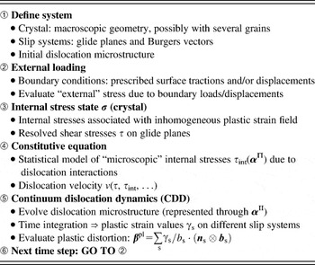
Only in recent years, conceptual progress has been made by HochrainerReference Hochrainer23, Reference Hochrainer, Gumbsch and Zaiser24, Reference Hochrainer, Zaiser and Gumbsch25, Reference Sandfeld, Hochrainer, Zaiser and Gumbsch42 that allows to define and handle such objects in a controlled and mathematically consistent manner. This CDD theory is based on the description of connected dislocation lines by a generalized dislocation density tensor. Systematic averaging of dislocation configurations leads to evolution equations for density-like variables, which represent the averaged dislocation state as well as the motion, multiplication, and reactions of curved dislocation lines in a continuum setting. Having formulated the kinematic problem one can then combine this formulation with a constitutive relation for the dislocation velocity and embed the whole into a crystal plasticity framework as shown in Table I.
Interplay between CDD, constitutive relation and crystal plasticity framework: External and internal stresses determine dislocation velocities. Internal stresses arise from spatially inhomogeneous plastic distortion fields and from short-range dislocation–dislocation interactions. CDD provides the kinematic closure by evolving the dislocation microstructure, which is used for evaluation of stresses in a next time step.

The strength of this approach becomes particularly obvious when we look at the problem of BCs for phenomenological gradient plasticity models. In a dislocation density-based approach, nonlocal terms are related to dislocation fluxes; thus, the required additional BCs acquire a simple physical meaning: can dislocations freely leave a surface, are surface sources available to allow an influx of dislocations, and are internal boundaries penetrable or impenetrable? Formulated on this level, it is evident that the problem of BCs has no general “canonical” answer but depends on the actual properties of the system at hand.
A. Basic concepts of CDD
Our approach toward formulating a continuum theory of dislocation dynamics is based on a modified definition of the dislocation density tensor. In a continuum framework where individual dislocation lines can no longer be resolved, the classical dislocation density tensor (the Kröner–Nye tensor) averages over the line directions l of all dislocations contained within a volume element. Because dislocation segments move normal to their line direction, this average contains sufficient kinematic information only if all these dislocation lines have the same orientation, i.e., when they form smooth bundles of parallel lines. By contrast, the second order dislocation density tensor (SODT) αII that is used by CDD distinguishes dislocations a priori by their line direction before any averaging is introduced. In this manner, SODT is able to describe the kinematics of very general systems of dislocations. It is limited only by the assumption that those dislocation lines in a given volume element, which share the same orientation “ϕ” also have the same curvature “k” and velocity “v.” Dislocations of different orientations, on the other hand, may possess different curvatures and velocities, and of course they move in different directions. Note that if the velocity depends solely on the spatial position, CDD remains valid even if dislocations of the same orientation have different curvatures.
This extended validity is achieved by defining αII in a higher-order configuration space. For illustration we consider dislocations—represented by a scalar dislocation density ρ—that move by glide only within glide planes, which we assume perpendicular to the z axis of a Cartesian coordinate system. In this case αII is defined on the configuration space ℝ × ℝ × S, where S is the orientation space [0, 2π). In the following r is a point in ℝ × ℝ and (r,ϕ) denotes a point in ℝ × ℝ × S. With l(ϕ) = (cos ϕ, sin ϕ) defining the canonical spatial line direction and L(r,ϕ) = (l(ϕ), k (r,ϕ)) defining the generalized line direction in the higher-order configuration space, α II takes the form

where b is the Burgers vector, which we assume to point in the positive x direction and ⊗ denotes the tensor product. The evolution equation for this tensor has the formReference Hochrainer23, Reference Sandfeld, Hochrainer, Zaiser and Gumbsch42:

where the vector V(r,ϕ) = (v(r,ϕ), ϑ (r,ϕ)) denotes the generalized velocity in configuration space, which is perpendicular to the generalized line direction. In analogy to the generalized line direction, this consists of spatial components v = v(r,ϕ)ν(ϕ), where ν = (sin ϕ, −cos ϕ) and v is the scalar velocity of dislocation segments threading a volume element at r with orientation ϕ, and an angular component ϑ(r,ϕ), which gives the rotation velocity of these segments. ϑ can be evaluated as the negative derivative of the velocity along the generalized line direction, ϑ = −∇L(v). Assuming that dislocations move by glide only, Eq. (2) is equivalent to a set of two coupled scalar evolution equations for the total density ρ(r,ϕ) and the mean curvature k(r,ϕ) (compare Ref. 23):


where we dropped the subscripts (r,ϕ) of ρ, k, v, and ϑ for brevity and denote the derivative of the curvature along the generalized velocity by ∇V(k).
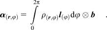
Dislocation density measures used by previous authors (compare Sec. II. C) can be recovered from the density function ρ(r,ϕ) in a straightforward manner. For instance, the Kröner–Nye tensor can be obtained from Eq. (1) as
The numerical implementation of CDD was explored recently.Reference Sandfeld, Hochrainer, Zaiser and Gumbsch42–Reference Sandfeld, Zaiser and Hochrainer44 Besides analyzing the performance in some numerical benchmark problems, it was shown that the theory allows tackling physically relevant microplasticity problems with simple deformation geometries. At the same time these studies have shown that, because of the large number of degrees of freedom required for conducting simulations in a higher-dimensional state space, the computational effort and memory storage capacity required for simulation of larger systems [e.g., a truly three-dimensional (3D) polycrystal with multiple slip systems] might become limiting factors for the straightforward application of CDD. This gives rise to the question whether CDD can be simplified to reduce the number of degrees of freedom.
B. Simplified form of CDD
In Refs. 26 and 41 it was shown that a significant reduction of the degrees of freedom required in CDD simulations can be achieved if one makes some simplifying assumptions. Starting from the higher-dimensional dislocation-based field theory one can partially integrate the governing evolution equations to drastically decrease the number of unknowns per glide system. In the following, the resulting model will be abbreviated as sCDD—simplified Continuum Dislocation Dynamics.
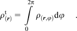
The internal variables used by sCDD are obtained from those used by CDD by integrations over orientation space. In the following we illustrate this for the specific case of dislocation glide on a single slip system with notations as in the previous section. The total dislocation density ρ t can be obtained by simply integrating the higher-order density function over the orientation variable:
The total geometrically necessary dislocation density is defined as  , where κ 1 and κ 2 are related to the (11)- and (12)-components of the Kröner–Nye tensor by

Similarly, the evolution equations for κ 1 and κ 2 can be obtained by weighting the evolution of the density function ρ in Eq. (3) with the trigonometric functions sin(ϕ) and cos(ϕ) and integrating over the angular coordinate. This yields

The evolution equation for the total dislocation density follows as

where the last term accounts for change of density due to expansion or shrinkage of dislocation loops. Equations (8) and (9) together represent transport of geometrically necessary and total dislocation densities and account for the average orientation of the dislocation lines. These three evolution equations are complemented by an evolution equation for the average curvature  ,
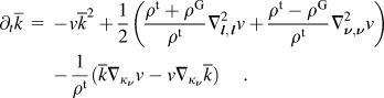
The expressions  and
 are second derivatives of the velocity in the average line direction and in the average velocity direction of the dislocation ensemble. These derivatives can be expressed in terms of the “components” κ 1 and κ 2 of the GND density and are defined as
 ,
 . Finally, the gradient operator in the last two terms is defined as
 .
Equations (8), (9), and (10) are derived from the full equations of CDD under the following assumptions: (i) the scalar dislocation velocity in a spatial point r is independent of the line orientation ϕ even though the velocity vectors v = vν of course differ and (ii) dislocations in the same point have the same mean curvature regardless of their orientation.
IV. NUMERICAL EXAMPLE: BENDING OF A THIN FILM
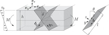
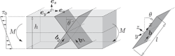
As an application of sCDD, we study the problem of microbending of a free-standing thin film of thickness h. The film is deformed by bending around an axis parallel to the y direction. Dislocations can move on two slip systems that are symmetrically inclined with respect to the surface normal e s as shown in Fig. 1. The Burgers vector of each slip system is perpendicular to the y axis, hence, deformation is in plane strain. The system is homogeneous in the directions parallel to the free surfaces.
Bending simulations: investigated slip geometry and coordinate system. The τ 0 is the bending stress (resolved shear stress in the slip systems) in the absence of plastic deformation, the system is assumed to have infinite extension in the y direction, we assume two symmetrical slip systems with slip planes inclined by θ = π/6 with respect to the normal e s of the film.

For symmetry reasons both slip systems are equivalent. Thus, we need to investigate the evolution of strain and dislocation densities for only one of them. Because the system is homogeneous in two directions, the problem depends on a single coordinate x, which we take in the Burgers vector direction of the considered slip system (see Fig. 1). The shear stress in the slip system can be formally envisaged as the sum of a reference shear stress τ 0, which describes the stress state in a film that is bent in a purely elastic manner, and a shear stress τ 1 related to the plastic strain γ, which we evaluate by assuming isotropic material properties and making the standard assumption that straight specimen cross sections remain straight during bending. These stresses are given by
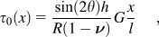

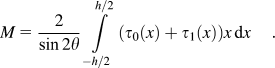
where R is the bending radius, G the shear modulus of the material, ν Poisson’s number, and l the film width projected on the x direction. The bending moment M (moment per unit length in the y direction) is evaluated as
To obtain a mathematically closed description, we need to complement our kinematic theory with a constitutive model that links the dislocation velocity to the stress and the density functions that describe the dislocation structure. We use a linear-viscous model of overdamped dislocation motion where the dislocation velocity depends on the difference between the local shear stress τ 0 + τ 1, a local yield stress

and a back stress τ b, e.g., proposed in Ref. 51, which for the present problem can be written as
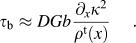
In these relations, “a” and “D” are geometry-dependent parameters with a = 0.2 . . . 0.5 and D = 0.5 . . . 1.0, respectively.Reference Groma, Csikor and Zaiser20 Yield stress and back stress provide a statistical description of short-range dislocation interactions leading to dislocation configurations that are immobile at low stress (dislocation dipoles, multipoles, junctions) and to piling up of dislocations of the same sign. In the language of traditional continuum theories, τ y describes isotropic hardening while τb contributes to kinematic hardening. The velocity function is

We consider two types of BCs at the film surface: (i) with “open” BCs, dislocations of all orientations are allowed to thread the surface and to freely enter or leave the film. This is achieved by extrapolating the dynamics inside the film across the boundary. This implies that the surface has no influence whatsoever on the local stresses, and the activation stress of surface sources matches the yield stress of the dislocation system underneath the surface; (ii) with “image stress” BCs we mimic the situation in 3D DDD simulations where the motion of dislocation segments that are very close to the free surface is controlled by image stresses. For the particular geometry in our simulations the edge components are attracted by the surface. Thus, the κ 2 component is reduced in these regions, i.e., the strain gradient at the surface tends to vanish.
As an initial condition, we assume an isotropic dislocation distribution with zero mean curvature  , space-independent total dislocation density ρ t = 2 × 10¹³m−2, and zero GND densities κ 1 and κ 2. This characterizes a statistically homogeneous and isotropic arrangement of dislocation lines that are straight on average.
We carry out strain-controlled bending tests where we prescribe the bending radius R or, equivalently, the tensile/compressive strain ε a = ±h/(2R) (axial strain in the direction of e a) at the free surfaces of the film. The bending radius is decreased in small steps. Each step leads to an increase in the stress τ0 followed by a relaxation phase during which the dislocation system evolves and the plastic strain increases. Because of the resulting changes in internal stresses, the strain rate gradually decreases toward zero. We trace this relaxation until the strain rate has everywhere dropped below a prescribed low level and then record the bending moment M, strain profile γ(x), and the dislocation patterns ρ t(x) and κ 1,2(x). We note that for the case of “open” BCs we have studied the same problem in an earlier publication using a numerical implementation of CDD.Reference Sandfeld, Hochrainer, Zaiser and Gumbsch42 Results from CDD and sCDD for this case are practically identical.Reference Sandfeld41 For different initial conditions (all dislocations are initially straight and have screw orientation), analytical results with “image stress” boundary conditions were given in Ref. 51. Comparison of these earlier results with the present computations indicates that the choice of initial conditions does not strongly influence the deformation behavior.
To parameterize our sCDD simulations, we compare with stress–strain curves and strain profiles obtained from 3D DDD simulations of bending of [100]-oriented Al microbeams. Details of these simulations can be found in Ref. 34. The method used for extracting the strain profiles is described in Ref. 4. The initial dislocation density and initially isotropic dislocation arrangement in the DDD simulations match our sCDD initial conditions. The parameter “a”, which in our constitutive model describes the strength of dislocation-forest interactions is chosen as a = 0.65. This relatively high value is needed because in the DDD simulations each moving dislocation interacts with a “forest” of 9 slip systems, while in the present simulation only one forest system is present. To achieve comparable yield stresses we chose the simple expedient of adjusting “a” to a high value. The slip system angle θ = π/6 defines a pseudo-fcc slip geometry, which allows to directly compare sCDD and DDD simulations.
V. RESULTS
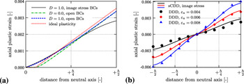
The qualitative shape of the strain profiles deduced from our simulations depends strongly on both the description of internal stresses and the chosen BCs. Figure 2(a) compares the strain profile expected according to classical ideal plasticity with the predictions of sCDD. The classical profile [dotted line in Fig. 2(a)] consists of a central elastic core and outer plastic regions where the plastic strain increases linearly toward the surface. The sCDD without back stresses (D = 0) and with open boundary conditions produces an almost identical result [dash-dotted line in Fig. 2(a)]. The only visible difference is a slight reduction in plastic strain as the accumulation of GND increases the yield stress in the plastic region. Simulations with an appreciable back stress (D = 1), but the same open boundary conditions [dashed line in Fig. 2(a)], show an elimination of the elastic core, which is replaced by a turning point with zero strain located on the neutral axis, while the strain profile in the near-surface regions remain practically unchanged in comparison with the D = 0 case. Simulations with D = 1 and “image stress” BCs, finally, show the same behavior in the core as with open BCs. However, the strain profile is now markedly curved toward the surface, where plastic deformation is reduced in comparison with the other models.
Strain profiles obtained from continuum models and comparison with data obtained from DDD, all curves for h = 1.5 μm, plotted is the axial plastic strain εpa as a function of the distance from the neutral fiber. (a) Comparison of half-profiles predicted by the ideal plasticity theory (dotted line), sCDD with D = 0 and open BCs (dash-dotted line), sCDD with D = 1 and open BCs (dashed line), and sCDD with D = 1 and “image stress” BCs (full line), all profiles have been evaluated for a total surface strain ε = 0.004. (b) Comparison of DDD strain profiles at different surface strains as indicated in the graphs with the sCDD prediction using D = 1 and “image stress” BCs.

Comparison with strain profiles from DDD [Fig. 2(b)] demonstrates that only the results of the D = 1 calculations with “image stress” BCs match the DDD strain profiles, which are characterized both by the absence of an elastic core and by a pronounced reduction of the strain gradient toward the surface. With the parameterization we use, the sCDD strain profiles evaluated in this manner are in quantitative agreement with the DDD results.
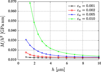
Agreement between DDD and sCDD is also found when we turn to the size dependence of the deformation behavior (Fig. 3). The DDD simulations predict an increase of the flow stress (scaled bending moment M/h 2) with decreasing h according to (M − M ∞)/h 2 ∝ h −β where M ∞/h 2 is the scaled bending moment of a film of macroscopic thickness, which according to classical plasticity does not depend on h and β is the size effect exponent for which Ref. 34 gives a value of β = 1.1 − 1.2. This is in good agreement with the results of the sCDD simulations, which indicate a size effect exponent of β ≈ 1.15.
Size dependence of the flow stress (normalized bending moment) for different surface strains, all simulations with back stress (D = 1) and “image stress” BCs.

VI. DISCUSSION
To better understand the physical mechanisms underlying the shape of strain profiles and the size effect, we looked at the profiles of total dislocation and GND densities (Fig. 4) and at the internal stress profiles (Fig. 5). To illustrate the key points, we compared a system without back stress and with open BCs, and a system with back stress and with “image stress” BCs. In the absence of back stresses, GND are evenly distributed over the plastic zone, while they remain absent from the elastic core. Back stresses lead to mutual repulsion of GND, which pushes them into the core region and lead to plastic flow throughout the film with the sole exception of the neutral fiber. (We note that, in individual DDD simulations, the mutual interactions between dislocations emitted from the same source may push them across the neutral fiber, leading to fluctuations in plastification. However, such fluctuations average out between different simulations, and the behavior after ensemble averaging is well described by the sCDD result.)
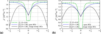
Comparison of total density and GND density profiles for (i) a system without back stress (D = 0.01) and with open BCs; (ii) a system with back stress (D = 1) and with open BCs, (iii) a system with back stress (D = 1) and “image stress” BCs. (a) Total dislocation density and (b) GND density, all profiles have been evaluated for h = 1.5 μm and total surface strain εtot = 0.004.

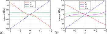
Comparison of converged stress profiles (i.e., the resulting stress and dislocation velocity are vanishing) for (a) a system without back stress (D = 0.01) and with open BCs; (b) a system with back stress (D = 1) and with open “image stress” BCs. Shown are the stress contributions τ1 and τ2, yield stress τy, and back stress τb. All profiles have been evaluated for h = 1.5 μm and total surface strain εtot = 0.004.

While the dislocation pattern in the core does not depend appreciably on BCs, these have a strong influence near the surface. Open BCs (dashed lines) allow free influx of excess dislocations and lead to a situation where both GND and total dislocation densities are highest at the surface. “Image stress” BCs, on the other hand, lead in conjunction with a back stress to a decrease of near-surface dislocation densities as GND are pushed out of the surface, which acts as a GND sink. The action of back stresses is illustrated by the stress profiles shown in figure Fig. 5. Figure 5(a) shows stress profiles in the absence of back stresses and with open BCs that allow a free influx of GND. There is an elastic core where the dislocation density remains at its initial level; outside this core the yield stress is slightly elevated due to the accumulation of geometrically necessary dislocations, which cause size-dependent hardening. In the presence of back stresses and with “image stress” BCs [Fig. 5(b)], the internal stress pattern changes appreciably. Back stresses facilitate plastic flow near the neutral fiber, where the elastic core of classical theory is eliminated. Near the surface, on the other hand, the sign of the back stresses changes and they impede plastic flow by pushing GNDs out of the film. The resulting GND depletion leads to a decrease of the yield stress in the near-surface region. This is, however, more than compensated by the action of the back stresses in this region, which again leads to a net increase of the bending moment with decreasing film thickness.
Comparing the two cases neatly illustrates the importance of surface boundary conditions in size-dependent hardening. Open BCs allow for a maximum influx of GND and thus promote a mechanism of size-dependent hardening that is based on the accumulation of GNDs, which contribute to the Taylor-type yield stress, as proposed, e.g., in Refs. 16 and 36. Back stresses and “image stress” BCs, on the other hand, lead to surface depletion of GNDs, which renders this mechanism ineffectual. Instead, size-dependent hardening is governed by the mutual repulsion of GNDs as described by the back stress term. It is interesting to note that the size-dependent contribution to the bending moment is much larger in the latter case: For otherwise identical parameters, it is in simulations with D = 1 and “image stress” BCs about twice as large as in simulations with D = 0 and open BCs. In conjunction with the DDD strain profiles, which show a reduced strain gradient and hence a depletion of GND in the near-surface region, this points to the importance of mutual repulsion of GNDs as a key factor in size-dependent deformation.
VII. CONCLUSION
Dislocation-based modeling of crystal microplasticity requires combining kinematically consistent models of dislocation density evolution with physically founded descriptions of dislocation interactions. We introduced two kinematically consistent formulations of continuum dislocation dynamics (CDD and the condensed version sCDD). In conjunction with a statistical description of dislocation interactions in terms of a Taylor-type yield stress and a back stress, which describes short-range repulsion of dislocations of the same sign, sCDD proved capable of capturing key features of DDD simulations. In particular, we could relate the elimination of the “elastic core” of bending specimens to the repulsive back stresses acting between piled up excess dislocations.
A particular advantage of the present approach is the possibility of linking BCs of the gradient-dependent equations to the physics of dislocation motion near surfaces and interfaces. Thus, the characteristic flattening of strain profiles near surfaces observed in DDD simulations could be interpreted in terms of image stresses, which eliminate GND in the immediate vicinity of the free surface. In the continuum setting of sCDD such image stresses, which act on the scale of individual segments, cannot be directly implemented; however, their effect can be straightforwardly mimicked by treating the surface as a GND sink. In conjunction with mutual repulsion of GND, as described by back stresses, this leads to strain profiles that are in quantitative agreement with those predicted by DDD.
In conclusion, we have demonstrated that new dislocation-based continuum approaches toward plasticity modeling are capable of quantitatively modeling not only size-dependent deformation curves, but also the associated evolution of dislocation and internal strain patterns. DDD simulations give complete access to internal stress and strain patterns and can thus serve as an important tool for parameterizing and validating dislocation-based (and other) continuum approaches. Comparison of strain patterns deduced from DDD with those obtained from continuum approaches can help to understand the nature of boundary conditions and to benchmark the performance of constitutive models. We therefore hope that a judicious combination of continuum modeling and discrete simulation will allow us to develop models that lead to a more profound physical understanding and better prediction of plasticity on micrometer and submicrometer scales.
ACKNOWLEDGMENT
Financial support of the Deutsche Forschungsgemeinschaft DFG under contracts HO4227/1 and GU367/30 is gratefully acknowledged.