


1. Introduction
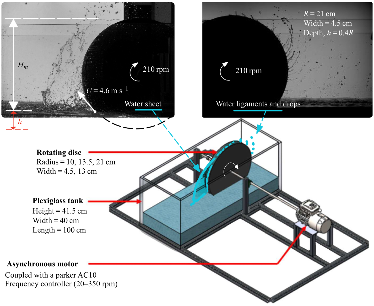
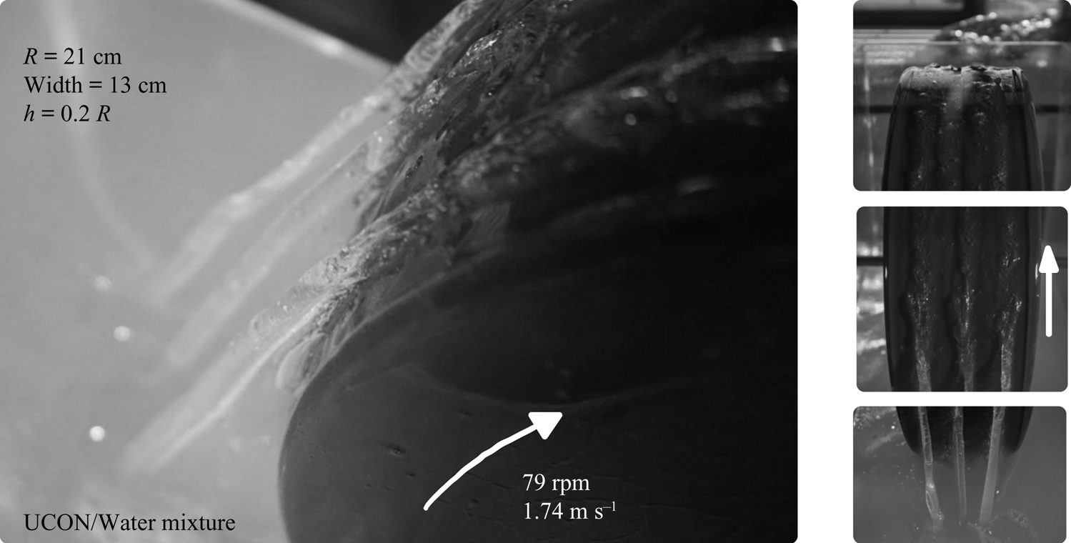
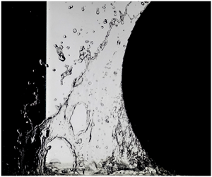
When we imagine a car rolling over a puddle, we picture a spectacular lateral liquid splash. While this common life phenomenon is interesting on its own, the liquid flux entrained along the rotating wheel rim, its subsequent atomization and dispersion on different parts of the vehicle, is also an important related issue. Now if we simplify both the wheel geometry and the flow domain by considering a smooth disc of finite width, partially submerged in a rectangular liquid tank (see § 2 for details about this set-up), we can observe two global features in the resulting flow as illustrated in figure 1. First, a liquid sheet stands out of the pool at the rear of the wheel, extending perpendicularly to its rim. Second, a non-uniform, unsteady liquid film is entrained on the rim, and is then atomized into ligaments and droplets. As presented in a series of photographs (see figures 2–5), the liquid sheet can either be stationary at sufficiently small speeds, or corrugated at higher speeds. When the disc width is increased multiple sheets can be observed, with each of them leaving a thick trail on the rim of the wheel. These liquid sheets may even meander along the rim, and also coalesce so that the number of sheets may vary with time. In addition, air bubbles are entrained on the plunging side of the wheel.
Water entrainment by a partially immersed rotating disc of radius  $R=21\ \textrm {cm}$, immersion depth
 $h=8.4\ \textrm {cm}$ and linear velocity
 $U=4.6\ \textrm {m}\ \textrm {s}^{-1}$. Two dominant liquid flow structures appear, namely, a liquid sheet and a liquid film flow which fragments into ligaments and droplets. Schematic of the experimental set-up showing a partially immersed rotating disc of finite width in a 1 m long aquarium.

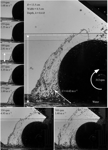
Instantaneous side view of the inertia-driven liquid menisci on a partially immersed rotating disc in water ( $R = 13.5\ \textrm {cm}$,
 ${h/R} = 0.4$). Linear velocities
 $U = \varOmega R$ corresponding to these conditions vary between
 $1.68$ and
 $5.48\ \textrm {m}\ \textrm {s}^{-1}$. See supplementary movie 1 available at https://doi.org/10.1017/jfm.2020.879 for more visualizations.

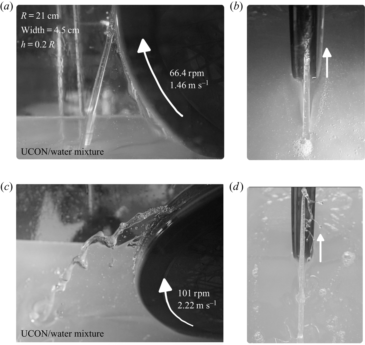
Photographs presenting both side (a,c) and front (b,d) views of the dynamic liquid sheet in a viscous UCON/water mixtures of dynamic viscosity  $\mu = 82 \times 10^{-3}\ \textrm {Pa}\ \textrm {s}$. Sheets can be stationary at low speeds or unsteady at higher speeds.

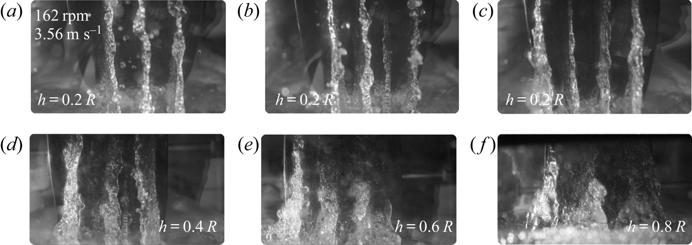
When a wider disc rotates in water ( $R = 21\ \textrm {cm}$, width
 $= 13\ \textrm {cm}$) multiple water sheets occur:
 $(a\text {--}c)$ Photographs at different instants for a given wheel immersion depth
 $h = 0.2 R$ and
 $U = 3.56\ \textrm {m}\ \textrm {s}^{-1}$ showing that the number of sheets may vary with time.
 $(d\text {--}f)$ Photographs at various immersion depths
 $h$ (distance between the water level and the disc's bottom). They resemble a fully developed inertial ribbing instability (Yih Reference Yih1960).

Photographs showing multiple liquid sheets for the same UCON/water mixtures and wheel radius as in figure 3 but for a wider disc ( $\textrm {width} = 13\ \textrm {cm}$) at
 $U = 1.74\ \textrm {m}\ \textrm {s}^{-1}$.

Our primary interest here is to study the simplest of the features in this inertia-dominated drag-out problem with the hope of providing some insights into high-speed liquid entrainment processes, thereby motivating future work. For this purpose, we abandon the more classical case of a long horizontal cylinder to avoid multiple sheets, and the associated multi-phase flow phenomena as well, in order to experimentally consider two simple questions: (i) How does the size of a single liquid sheet vary as a function of the disc speed  $U = R \varOmega$, liquid properties and immersion depth
 $h$? (ii) What is the resulting entrained liquid flux on the rotating disc? Our work is primarily experimental with an intention to bring out some scaling laws in relation to this inertia-dominated drag-out problem.
Liquid entrainment is very well documented for films on fibres that are dragged out of a liquid pool (Quéré Reference Quéré1999), for various coating flows between one or more horizontal rolls that feed/pull/spread a thin liquid film on a substrate (Ruschak Reference Ruschak1985; Benjamin, Anderson & Scriven Reference Benjamin, Anderson and Scriven1995; Weinstein & Ruschak Reference Weinstein and Ruschak2004), and also for film flows on the inside, or the outside, of a freely rotating drum (Thoroddsen & Mahadevan Reference Thoroddsen and Mahadevan1997; Seiden & Thomas Reference Seiden and Thomas2011). These works are crucial to study and model thin liquid film coating flows (Cohen & Gutoff Reference Cohen and Gutoff1992; Schweizer & Kistler Reference Schweizer and Kistler2012) and their stability (Yih Reference Yih1960; Pitts & Greiller Reference Pitts and Greiller1961; Coyle, Macosko & Scriven Reference Coyle, Macosko and Scriven1990). In this context, the present work may also actually be relevant to an important class of problems in both modern engineering and fundamental fluid mechanics involving high-speed entrainment of a liquid by a moving wall.
1.1. Landau–Levich–Deryaguin (LLD) flows: flat plate, or fibre, withdrawal from a liquid pool
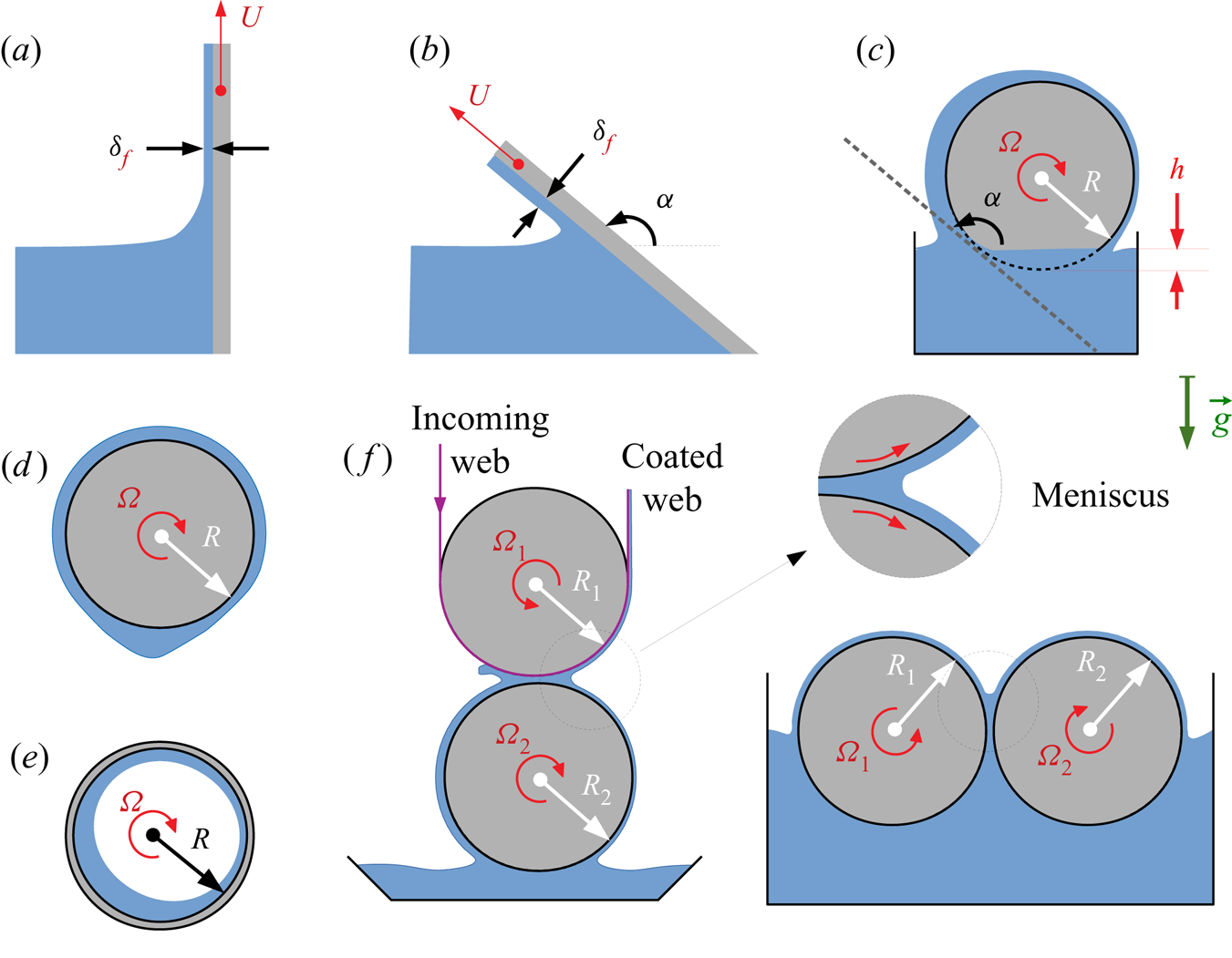
The simplest entrainment flow configuration is that of a liquid film entrained by a long vertical plate (figure 6a), or a thin vertical fibre, as it is withdrawn at a steady speed  $U$ from a large reservoir of a viscous liquid of density
 $\rho$, viscosity
 $\mu$ and surface tension
 $\sigma$. It is the so-called Landau–Levich–Deryaguin dip-coating flow (Goucher & Ward Reference Goucher and Ward1922; Morey Reference Morey1940; Landau & Levich Reference Landau and Levich1942; Deryaguin Reference Deryaguin1943; Van Rossum Reference Van Rossum1958). The liquid surface tension plays a subtle role on the coating flow via the Laplace pressure at the dynamic meniscus between the film and the reservoir. However, far away from the dynamic meniscus, the flat entrained film is at the ambient pressure. Consequently, a pressure gradient which opposes liquid entrainment should exist along the vertical film. Landau & Levich (Reference Landau and Levich1942) and Deryaguin (Reference Deryaguin1943) were the first to remark on this feature for the case when the surface tension forces dominate viscous entrainment, i.e. at sufficiently small capillary numbers
 $Ca = \mu U / \sigma$ and at negligible inertia. They showed that the liquid film thickness far away from the reservoir is given by
 \begin{equation} \delta_f^{(LLD)} \simeq l_c [0.946 Ca^{2/3} - 0.107 Ca + \mathcal{O} (Ca^{4/3})], \end{equation}
where  $l_c = \sqrt {{\sigma }/{\rho g}}$ is the capillary length with
 $g$ the acceleration due to gravity (note that the higher-order terms in capillary number are first developed by Wilson (Reference Wilson1982) using a matched-asymptotic technique). This pioneering result correlates well with numerous experimental investigations for small capillary numbers up to
 $\mathcal {O}(10^{-2})$ (Morey Reference Morey1940; Van Rossum Reference Van Rossum1958; Groenveld Reference Groenveld1970c; Snoeijer et al. Reference Snoeijer, Ziegler, Andreotti, Fermigier and Eggers2008; Maleki et al. Reference Maleki, Reyssat, Restagno, Quéré and Clanet2011) and also, for moderate values of
 $Ca$ (White & Tallmadge Reference White and Tallmadge1965; Groenveld Reference Groenveld1970b; Spiers, Subbaraman & Wilkinson Reference Spiers, Subbaraman and Wilkinson1974; Kizito, Kamotani & Ostrach Reference Kizito, Kamotani and Ostrach1999).
Some common liquid entrainment configurations:  $(a)$ The classical Landau–Levich–Deryaguin dip-coating flow.
 $(b)$ Tallmadge's (Reference Tallmadge1971) variant of LLD flow which Tharmalingam & Wilkinson (Reference Tharmalingam and Wilkinson1978) used to model, as schematized in
 $(c)$, the coating flow on a partially submerged rotating drum at different immersion heights; Rubashkin (Reference Rubashkin1967), Groenveld (Reference Groenveld1970a) and Middleman (Reference Middleman1978) also used this rotating cylinder set-up to explore the large capillary number limit. (
 $d$,
 $e$) Moffatt–Pukhnachev–Yih (MPY) external, or internal, rimming flows, respectively.
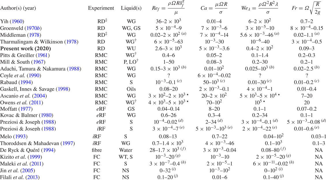
 $(f)$ Other examples of rotary entrainment in liquid film coating processes (for more, refer to Schweizer & Kistler Reference Schweizer and Kistler2012). Relevant non-dimensional numbers in several previous experiments and computations are given in table 2.

When both inertia and surface tension are negligible compared to viscous forces and the film is flat far away from the liquid bath, the film thickness  $\delta _f$ can be deduced from a simple balance between the weight of the liquid film and the viscous drag of the plate. Thus, in this viscosity–gravity driven regime, the relevant length scale for the film thickness is
 \begin{equation} \delta_f^{(g)} = \sqrt{\dfrac{\mu U}{\rho g}} = l_c Ca^{1/2}, \end{equation}
as one could expect from the classical drainage problem (Jeffreys Reference Jeffreys1930; Chalmers Reference Chalmers1937). But the presence of a stagnation point in the meniscus region between the pool and the moving plate (Groenveld Reference Groenveld1970a) implies that the resulting film thickness is provided by the expression (1.2) up to a constant factor, depending on the flow situations. Subsequent experiments (Groenveld Reference Groenveld1970b; Kizito et al. Reference Kizito, Kamotani and Ostrach1999) and two-dimensional computations (Jin, Acrivos & Münch Reference Jin, Acrivos and Münch2005; Filali, Khezzar & Mitsoulis Reference Filali, Khezzar and Mitsoulis2013) suggest that such a limit is attained at  $Ca \gg 1$ but only for moderate Reynolds number
 \begin{equation} Re_f = \dfrac{\rho U \delta_f^{g}}{\mu} \equiv \sqrt{\dfrac{Ca^3}{Mo}}, \end{equation}
based on 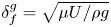 $\delta _{f}^{g} = \sqrt {{\mu U}/{\rho g}}$ which is the relevant length scale for the film entrained by an infinite vertical wall. Note that
 $Re_f$ is related to the capillary number via Morton number
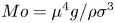 $Mo = \mu ^4 g / \rho \sigma ^3$ (or, equivalently, the fluid property number) which depends only on the fluid properties at a given
 $g$.
In this context, by extending the LLD model to include inertia, De Ryck & Quéré (Reference De Ryck and Quéré1998b) suggested that deviations from the classical LLD limit could occur due to an increased momentum transfer from the plate at the dynamic meniscus. Experimental data of Kizito et al. (Reference Kizito, Kamotani and Ostrach1999, in figure  $3$) indicate that deviations from the LLD law, to either larger or smaller film thicknesses, are attained at different capillary numbers depending only on the fluid property number, or Morton number
 $Mo$. While the measured film thickness for various viscous fluids plateaued out at approximately
 $0.7 \delta _f^{(g)}$ beyond a Weber number
 $Re_f Ca = We_f \approx 0.2$, it cannot be concluded from their data corresponding to less viscous liquids (
 $Mo \ll 1$) that this will be the case when
 $Re_f \gg 1$ since the maximum Reynolds number in their experiments was only approximately
 $20$.
Similarly, Jin et al. (Reference Jin, Acrivos and Münch2005) illustrated, using two-dimensional creeping flow equations ( $Re_f = 0$) for the dip-coating problem, that the film flow rate per unit width attains a constant value of approximately
 $0.58 \delta _f^{(g)}U$ when
 $Ca \gg 1$. They also attempted to investigate the role of inertia by varying the capillary number
 $Ca$ at different Morton numbers
 $Mo = \left \{ 1, 10^{-2}, 10^{-4}, 10^{-6} \right \}$. They observed that the liquid flux dragged out of a pool by a flat plate is correctly predicted by the LLD scaling (1.1), independent of
 $Mo$, until it reaches a maximum value which occurs at some characteristic capillary number depending only on the Morton number
 $Mo$. In particular, the entrained flow rate is smaller than
 $0.58 \delta _f^{(g)}U$ corresponding to their results for
 $Ca \gg 1$ and
 $Re_f = 0$ (or
 $Mo = \infty$). However, their numerical procedure failed beyond a critical value of capillary number at various Morton numbers
 $Mo$. Note that the maximum Reynolds number
 $Re_f$ attained in the two-dimensional simulations of Jin et al. (Reference Jin, Acrivos and Münch2005) was
 $32$ (
 $Mo = 10^{-6}$) and that they, like a good number of other works (Middleman Reference Middleman1978; Campanella & Cerro Reference Campanella and Cerro1984; Kizito et al. Reference Kizito, Kamotani and Ostrach1999; Evans, Schwartz & Roy Reference Evans, Schwartz and Roy2005; Filali et al. Reference Filali, Khezzar and Mitsoulis2013), suggest the formation of cusped menisci and wavy free-surface structures on the liquid pool as
 $Re_f$ increases.
Other works on liquid entrainment by a moving flat plate, or a fibre, in relation to LLD scaling considered the role of non-Newtonian rheology (De Ryck & Quéré Reference De Ryck and Quéré1998a), wettability (Snoeijer et al. Reference Snoeijer, Delon, Fermigier and Andreotti2006, Reference Snoeijer, Ziegler, Andreotti, Fermigier and Eggers2008), surfactants (Krechetnikov & Homsy Reference Krechetnikov and Homsy2005; Campana et al. Reference Campana, Ubal, Giavedoni and Saita2010; Mayer & Krechetnikov Reference Mayer and Krechetnikov2012), adsorbed particles on fluid interfaces (Campana et al. Reference Campana, Ubal, Giavedoni and Saita2011; Dixit & Homsy Reference Dixit and Homsy2013; Jung & Ahn Reference Jung and Ahn2013; Gans et al. Reference Gans, Dressaire, Colnet, Saingier, Bazant and Sauret2019; Palma & Lhuissier Reference Palma and Lhuissier2019), textured flat plates (Seiwert, Clanet & Quéré Reference Seiwert, Clanet and Quéré2011; Nasto, Brun & Hosoi Reference Nasto, Brun and Hosoi2018) and also the existence of non-unique solutions for the LLD problem (Weinstein & Ruschak Reference Weinstein and Ruschak2001; Benilov et al. Reference Benilov, Chapman, Mcleod, Ockendon and Zubkov2010).
1.2. Rotary entrainment, an inclined LLD flow?
Rubashkin (Reference Rubashkin1967) and Middleman (Reference Middleman1978) investigated the relevance of the LLD scaling (1.1) for the case of a partially immersed rotating cylinder. Using horizontal cylinders of radius  $R = 2.5$–
 $4\ \textrm {cm}$ and approximately
 $10$–
 $20\ \textrm {cm}$ long in a viscous oil bath, they reported, as others before, that the film thickness attains the limiting value of approximately
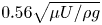 $0.56 \sqrt {{\mu U}/{\rho g}}$ as the capillary number is increased. They also noted, however briefly, that increasing the rotational speed of the cylinder destroys the dynamic meniscus. Tharmalingam & Wilkinson (Reference Tharmalingam and Wilkinson1978) provided further film thickness measurements for a wide variety of liquids as a function of the drum's rotational speed (
 $\varOmega$) at various cylinder immersion heights (
 $h$) under laminar flow conditions. In all these cases, there was no account of liquid sheets standing out of the liquid pool along the emerging side of the rotating cylinder similar to what is seen in photographs provided here (see figures 4 and 5). This is probably due to the small working Reynolds number
 $Re_f$, or strong confinement effects.
These authors attempted to account for the effect of immersion height on the liquid flux entrained by a rotating drum by modelling the latter as an analogous Landau–Levich–Deryaguin dip-coating flow over an inclined flat plate (see also, Tallmadge Reference Tallmadge1971; Wilson Reference Wilson1982; Jin et al. Reference Jin, Acrivos and Münch2005). In particular, as depicted in figure 6(b,c), if  $\alpha$ is the angle between the inclined plate which is tangent to the partially immersed cylindrical drum at its line of contact with the liquid bath at rest and the horizontal line, they showed that the non-dimensional film thickness
 $T_0 = \delta _{f} \sqrt {\rho g \sin \alpha /\mu U}$ just after the dynamic meniscus between the cylinder and the liquid reservoir is given by
 \begin{equation} \dfrac{T_0}{{(1 - T_0^2)}^{2/3}} \sim 0.94 Ca^{1/6} {\left( \dfrac{\sin \alpha}{1 - \cos \alpha} \right)}. \end{equation}
With the advent of numerical techniques, earlier theoretical efforts (such as Soroka & Tallmadge Reference Soroka and Tallmadge1971; Tharmalingam & Wilkinson Reference Tharmalingam and Wilkinson1978) on the lubrication equations wherein inertial effects could be included via one-dimensional (1-D) film flow modelling and Oseen-like corrections were later complemented by fully nonlinear, but 2-D film flow, simulations (Cerro & Scriven Reference Cerro and Scriven1980; Nigam & Esmail Reference Nigam and Esmail1980; Campanella & Cerro Reference Campanella and Cerro1984; Hasan & Naser Reference Hasan and Naser2009). Along with Tharmalingam & Wilkinson (Reference Tharmalingam and Wilkinson1978), these authors reported that the modified LLD scaling for an inclined plate, as in (1.4), holds for a good range of small capillary numbers. They also noted that, by including inertial effects in the inclined-plate LLD law, a better match was obtained with experiments when the film Reynolds number is of  $\mathcal {O}(1)$.
1.3. Rotary entrainment in roll coating and rimming flows
A related problem is that of the steady and unsteady motion of a thin liquid film on the outside of a freely rotating cylinder, or on the inside of a hollow rotating cylinder (as in figure 6d,e). They are known as external, or internal, rimming flows, respectively. These flows are also referred to as Moffatt–Pukhnachev–Yih flow (Yih Reference Yih1960; Moffatt Reference Moffatt1977; Pukhnachev Reference Pukhnachev1977). In the context of pattern formation, a large body of work exists for such thin film flows since rimming flows are prone to both azimuthal and axial non-uniformities (see Evans et al. Reference Evans, Schwartz and Roy2005; Seiden & Thomas Reference Seiden and Thomas2011 and references therein). Even though flow patterns in internal rimming flows (Kovac & Balmer Reference Kovac and Balmer1980; Thoroddsen & Mahadevan Reference Thoroddsen and Mahadevan1997) seem to be relevant to the present study, the liquid puddle confinement is very strong in these flows. In the case of external rimming flows, the rotating cylinder is not in continuous contact with the liquid puddle and therefore, the liquid mass entrained by the former is not constantly renewed. These differences might strongly alter the flow patterns such as the liquid sheet height and the resulting liquid entrainment process when the Reynolds number  $Re_f$ is sufficiently large. In this context, questions regarding the relevant length and time scales of the liquid sheet, the entrained flux are yet not well known.
Note that a very large panel of coating flows involving rollers (Schweizer & Kistler Reference Schweizer and Kistler2012, part  $3$) also fall under the category of rotary entrainment. In these cases the gap between the rollers is often very small (approximately one tenth of the roller radius or smaller) and the cylinder length-to-radius ratio is large. Therefore, as proposed first by G.I. Taylor, the flow field is almost always divided into two regions (Schweizer & Kistler Reference Schweizer and Kistler2012, see chapter
 $12$): 2-D flow in the liquid meniscus, or the film-splitting region (figure 6f), and a thin film flow far away from the meniscus. In fact, these flows can also exhibit azimuthal film thickness variations (Ruschak & Scriven Reference Ruschak and Scriven1976), axial patterns (Pitts & Greiller Reference Pitts and Greiller1961; Coyle et al. Reference Coyle, Macosko and Scriven1990) and even misting, or meniscus break-up and atomization, at high speeds (Owens et al. Reference Owens, Vinjamur, Scriven and Macosko2011). Unlike what is common in roller coaters, in the case we study here there is hardly any confinement on the emerging side of the disc so that the meniscus, or the liquid sheet, is not constrained by another disc. In addition, a long cylinder can lead to multiple liquid sheets when
 $Re_f \gg 1$, as already shown in figures 4 and 5.
Previous experimental and computational investigations on rotary entrainment often restricted the working Reynolds number  $Re_f$ based on coating thickness to small (or at best, moderate) values. When
 $Re_f$ was large, the meniscus was often strongly constrained as for example in roller coaters. An interested reader is referred to table 2, for more information on relevant dimensionless numbers in several earlier experimental and numerical investigations. Since both numerical and theoretical modelling of this fully three-dimensional, multi-phase and unsteady fluid flow is extremely difficult for the inertial rotary entrainment of liquids out of pool, we take a phenomenological approach in order to propose physical reasoning for the scaling laws observed in our experiment. In this regard, we focus in the remainder of this paper on the liquid sheet formed in front of a rotating disc of finite width at
 $h/R < 1$, and on the related entrained liquid flux at large
 $Re_f$ up to
 $10^3$.
2. Experimental set-up
As illustrated in figure 1, the experimental set-up consists of a large Plexiglass tank ( $40 \ \textrm {cm}\times 41.5 \ \textrm {cm}\times 100\ \textrm {cm}$) containing the working liquid. An asynchronous motor is used along with an AC Inverter Drive (Parker AC
 $10$) to rotate rigid PVC discs of radii
 $R = 10\ \textrm {cm}$,
 $13.5\ \textrm {cm}$ and
 $21\ \textrm {cm}$ and width
 $4.5\ \textrm {cm}$. Qualitative results for a thicker disc (
 $13\ \textrm {cm}$) were also presented in the introduction but experimental data in the following sections concern only these discs of thickness
 $4.5\ \textrm {cm}$. The angular velocity can be varied between
 $20$ and 350 rpm. The disc is partly submerged in the liquid bath and the liquid level
 $h$, as depicted in figures 1 and 6(c), is properly verified before each run. The position of the wheel's axis cannot be changed in the present set-up and so various immersion depths
 $h$ in the range
 $0.05$–
 $0.8$ times the disc radius
 $R$ are obtained by adjusting the volume of liquid in the aquarium.
Water and mixtures of water/UCON $^{\textrm{TM} }$ oil were chosen for the experiments (table 1). The viscosity of these mixtures can be controlled readily, and they are Newtonian. Note that temperature of the set-up was never imposed externally. The ambient temperature was relatively constant, and close to
 $23\pm 2\ ^{\circ }\textrm {C}$ during the experiments. Table 1 presents physical properties of the different liquids used in the experiments. Liquid density was measured using hydrometers whereas viscosity was obtained using a falling-sphere viscometer and by suitably taking into account the Reynolds numbers corrections for the viscous drag on the spheres (Brown & Lawler Reference Brown and Lawler2003). No surfactants were added to the working liquid in the present study. Surface tension measurements were performed using the pendant drop method with a tensiometer Attension Theta Flex (Biolin Scientific AB). Note that, for our water samples, the measured surface tension is comparable with the value for bubble-treated surface-clean water samples (Scott Reference Scott1975). This relatively high value was obtained by several independent measurements using our tensiometer.
Properties of working liquids in this study. Here, three different mass fractions of UCON $^{\textrm{TM} }$ lubricant 75-H-90 000 in water (denoted by
 $WU$) were used. The contact angle of Plexiglass–water in air and of Plexiglass–
 $WU3$ in air varied between
 $29^{\circ }\text {--}39^{\circ }$ and
 $32^{\circ }\text {--}71^{\circ }$, respectively. Note that the surface tension of water is relatively high compared to bubble-treated surface-clean water samples (Scott Reference Scott1975).

At first, the required wheel immersion depth is reached by controlling the water level while the wheel is at rest. Then, for a given liquid a typical series of experiments is performed by running the disc at a specific rotation rate as indicated by a tachometer. After a few seconds, the resulting average liquid sheet height ( $H_m$) and average film flow rate (
 $Q_f$) are measured. Then the angular velocity is increased to repeat measurements. Visualizations are carried out with the help of a LED panel (
 $59.5\ \textrm {cm} \times 59.5\ \textrm {cm}$) placed behind the liquid reservoir. Images are acquired with a Sony
 $\alpha 7$ camera (CMOS Sony Exmor). The following sections describe in detail both the measurement techniques and the corresponding results obtained using this experimental set-up.
3. Experimental results
3.1. Inertial menisci – a liquid sheet
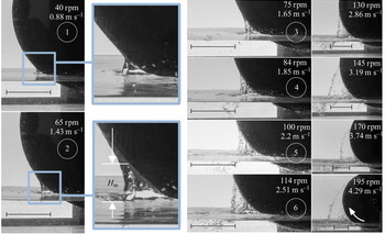
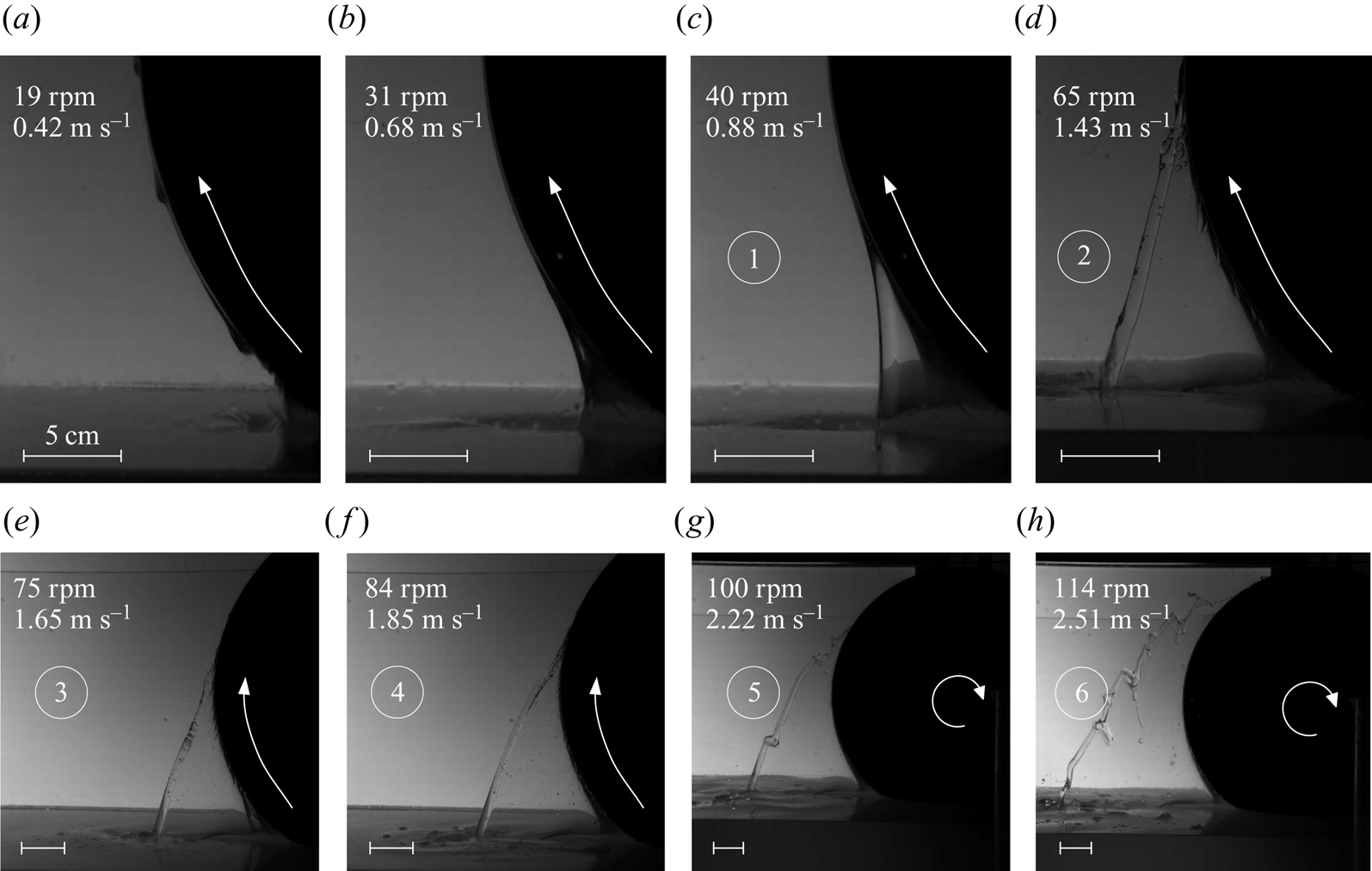
The series of photographs in figures 7 and 8 depicts the evolution of the emerging liquid sheet as the number of rotations per minute (rpm) is increased, for a wheel radius of  $21\ \textrm {cm}$ and a water level of
 $h = 0.2R$. As seen in the photographs of figure 7, the water level is almost constant across the lateral side of the wheel except close to the wheel's rim, at the bottom of the liquid sheet where the water level rises slightly. At the lowest of the speeds shown here in the photographs (40 rpm, or
 $U = 0.88\ \textrm {m}\ \textrm {s}^{-1}$, corresponding to
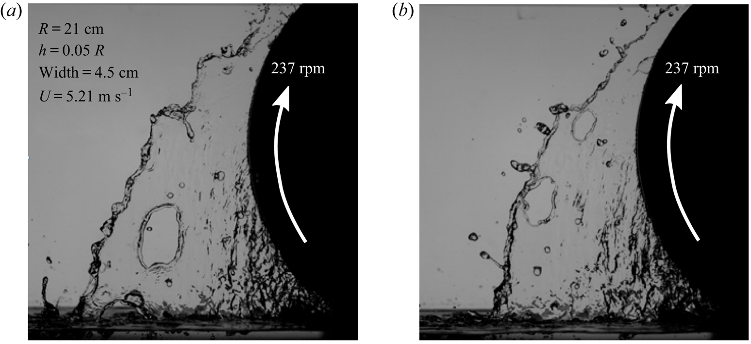
 $Re_f = \rho U \delta _f^{g} / \mu \approx 270$), a small quasi-static meniscus appears at the contact between the wheel and the stagnant water far away from the wheel. A close up shows that even at this stage the flow on the disc's rim is distinct from the classical 2-D LLD flow. First, we can observe a small dimple at the location where the meniscus emerges from the liquid bath which is reminiscent of the cusped meniscus already observed for dip-coating flows in previous experimental (Kizito et al. Reference Kizito, Kamotani and Ostrach1999) and numerical investigations (Jin et al. Reference Jin, Acrivos and Münch2005; Filali et al. Reference Filali, Khezzar and Mitsoulis2013). Second, it is no longer a smooth two-dimensional (or axisymmetric) structure, as is the case for LLD films on flat plates (or fibres), but a closer inspection shows spatial variations in the sheet thickness and the presence of one or two liquid rims. A further increase in wheel speed leads to the formation of a liquid sheet with a single liquid rim. At higher speeds, the sheet size increases dramatically, and the rim presents fluctuations. Holes form within the sheet, and their rupture results in drop formation (see figure 8 and supplementary movie 2).
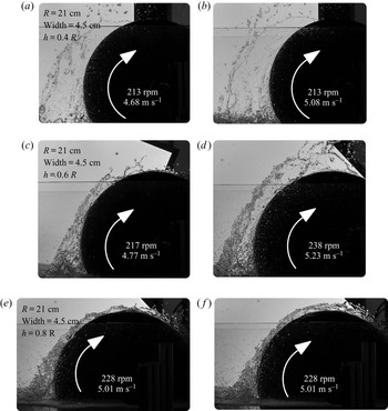
The influence of the immersion depth  $h$ of the wheel is illustrated in figures 9 and 10. In the former, the first four photographs (top and middle) compare instantaneous side views of the water sheet over a rotating disc of same radius
 $(R = 21\ \textrm {cm})$ and approximately same rotation speeds but with different liquid depths, namely,
 $h/R = 0.4$ and
 $h/R = 0.6$. First, it is clearly visible that the water sheet climbs as high as the wheel at approximately 215 rpm, or even higher at faster rotation rates. Second, the water depth
 $h$ does not seem to influence very much the water sheet height. A careful observation indicates that the water sheet is thicker at its base, just at the emerging side of the wheel's rim, and thereafter the sheet thins out. Observing the last of the two images in figure 9, it is inferred that the effect of water depth on the sheet height is not negligible for the case of
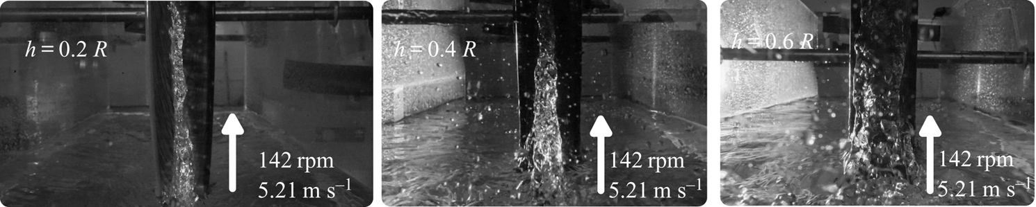
 $h/R = 0.8$ as compared to smaller depths. Moreover, instead of a thin liquid sheet a very thick mass of liquid is ejected in front of the wheel and also, a relatively thicker layer of water is entrained on top the wheel. Front views of these configurations, as presented in figure 10 at smaller speeds, also illustrate these observations on the sheet height and sheet thickness.
Instantaneous side view of the inertia-driven liquid meniscus on a partially immersed rotating disc in water ( $R = 21\ \textrm {cm}$,
 ${h/R} = 0.2$). Linear velocities
 $U = \varOmega R$ corresponding to these conditions vary between
 $0.88$ and
 $4.29\ \textrm {m}\ \textrm {s}^{-1}$. Displayed scales represent the half-radius of the disc
 $11.5\ \textrm {cm}$.

Visualization of the liquid sheet entrained by the wheel, for  $R=21\ \textrm {cm}$,
 $h=1\ \textrm {cm}$ and
 $U=5.21\ \textrm {m}\ \textrm {s}^{-1}$: holes form regularly on the water sheet and disintegrate it, leading to the formation of droplets.

Instantaneous side view of the inertia-driven liquid meniscus on a partially immersed rotating disc in water ( $R = 21\ \textrm {cm}$) at various immersion depths
 ${h/R}$. Linear velocities
 $U = \varOmega R$ corresponding to these conditions vary between
 $4.68$ and
 $5.23\ \textrm {m}\ \textrm {s}^{-1}$. Panels (e,f) compare the sheet height and the related liquid entrainment at the same speed but at different times.

Instantaneous front view of the inertia-driven liquid meniscus on a partially immersed rotating disc in water ( $R = 21\ \textrm {cm}$) at various immersion depths
 ${h/R}$ but for the same speed
 $U = 3.12\ \textrm {m}\ \textrm {s}^{-1}$. A sheet as thick as the wheel width is obtained for the case of
 $h/R = 0.8$.

The same phenomenology, with a few exceptions, is observed when a more viscous liquid is used (figure 11). Here, the liquid used is a water–UCON $^{\textrm{TM} }$ oil mixture
 $WU3$ (see table 1 for physical properties). Already at
 $U = 0.42\ \textrm {m}\ \textrm {s}^{-1}$ (
 $Re_f \approx 10$ and
 $Ca \approx 0.7$), a three-dimensional quasi-static meniscus appears. In addition, pendant drops are also seen to descend along the rim of the rotating disc (see supplementary movie 3). This film flow is similar to that observed by Evans, Schwartz & Roy (Reference Evans, Schwartz and Roy2004); Evans et al. (Reference Evans, Schwartz and Roy2005) in their numerical simulations of external rimming flows, or the classical MPY flow, at low speeds. No trace of descending pendant drops is seen at larger speeds but a quasi-steady liquid sheet emerging from the liquid bath is clearly visible. These images suggest that even in this highly viscous liquid, a lubrication approximation for the related flow may be irrelevant. At speeds up to
 $1.85\ \textrm {m}\ \textrm {s}^{-1}$ (
 $Re_f \approx 90$), a fine stable liquid sheet which terminates with a thick rim flow is observed. From these images of water–UCON
 $^{\textrm{TM} }$ oil mixtures (
 $WU3$), it is evident that the liquid rim is a result of a capillary recession, as in a Savart sheet (Savart Reference Savart1833; Villermaux, Pistre & Lhuissier Reference Villermaux, Pistre and Lhuissier2013). This recession is known to occur at the Taylor–Culick velocity of
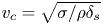 $v_c=\sqrt {\sigma /\rho \delta _{s}}$ where
 $\delta _{s}$ is the local liquid sheet thickness (Taylor Reference Taylor1959; Culick Reference Culick1960; Savva & Bush Reference Savva and Bush2009). As the speed is further increased, the rim of the sheet shows strong corrugations (see also, figure 3). Numbers are indicated for several images in figure 7 (for water) and figure 11 (for UCON
 $^{\textrm{TM} }$). They correspond to identical rotation rates for these series of experiments, and are provided to help the reader compare the height of the liquid sheet for different fluids. Such a comparison illustrates that the sheet height
 $H_m$ measured from the surface of the pool is approximately 3–5 times larger for the case of the most viscous liquid (
 $WU3$) than for the water case, at a given disc speed
 $U$.
Instantaneous side view of the inertia-driven liquid meniscus on a partially immersed rotating disc ( $R = 21\ \textrm {cm}$,
 ${h/R} = 0.2$) in a viscous liquid (
 $\mu = 82\ \textrm {mPa}\ \textrm {s}$), a mixture of UCON
 $^{\textrm{TM} }$ oil and water. Linear velocities
 $U = \varOmega R$ corresponding to these conditions vary between
 $0.42$ and
 $2.51\ \textrm {m}\ \textrm {s}^{-1}$. For a video see supplementary movie 4 to have closer look at the sheet, the rim and parabolic trajectories of entrained small bubbles inside the sheet when the wheel is rotating at 65 rpm.

3.1.1. Time-averaged sheet height
We have carried out measurements of the mean maximum liquid sheet height  $H_m$ above the surface of the pool, measured by visualization over a duration of 10 s. As seen in figures 1 and 2 (and also, figures 7 and 11),
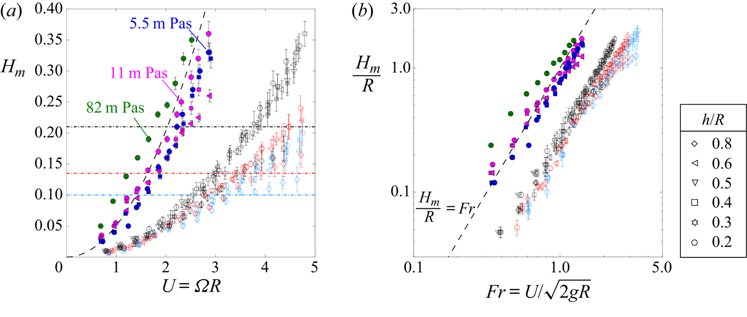
 $H_m$ is not necessarily measured at the point where the liquid sheet meets the wheel. These results are presented in figure 12 wherein the error bars correspond to minimum/maximum of the sheet height during the measurement window. Figure 12(a) presents these measurements as a function of the rotation speed
 $U$ for three disc radii and several depths
 $h$ for all working liquids. Here, filled symbols correspond to viscous UCON
 $^{\textrm{TM} }$/water mixtures and open symbols correspond to pure water.
Average liquid sheet height  $H_m$ (in m) with respect to the horizontal liquid level in the tank as shown in figures 1 and 2.
 $(a)$ Value of
 $H_m$ vs rotational speed
 $U = R \varOmega$ for various disc radii
 $R = 10$ (blue),
 $13.5$ (red),
 $21$ (black) cm and immersion depth to radius ratio
 $h/R$. Data correspond to the experiments with both pure water (open symbols) and various UCON
 $^{\textrm{TM} }$/water mixtures (
 $R = 21\ \textrm {cm}$, filled symbols). Dash-dot line correspond to radius of the wheel.
 $(b)$ Same data rescaled with respect to the Froude number
 $Fr = U/\sqrt{2gR}$. Dashed lines represent
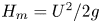 $H_m = U^2/2g$ (or simply,
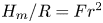 $H_m/R = Fr^2$). Note that the error bars indicate the amplitude of the fluctuations in the instantaneous value of sheet height.

Consider now all data when the working liquid is water. The sheet height  $H_m$ increases monotonically with velocity. In figure 12(a), each symbol corresponds to a different depth of immersion
 $h$ of the rotating wheel whereas colours of open symbols denote wheel radius
 $R$. We observe that the depth-to-radius ratio
 $h/R$ and the wheel radius
 $R$ seem to have little influence on the average height of the liquid sheet
 $H_m$, except for the cases at larger velocities. Especially for velocities approximately
 $3\ \textrm {m}\ \textrm {s}^{-1}$ and higher, the role of wheel radius is not negligible. We attribute this effect to the wheel's finite-size effect arising from the fact that here
 $h + H_m$ is
 $\mathcal {O}(R)$, or greater. So, it is expected that a smaller wheel (larger curvature) will lead to a smaller sheet for a given linear velocity
 $U$. In addition, this effect seems to be much more significant when
 $h/R = 0.8$ (denoted by
 $\diamond$) at all wheel radii and also, when
 $h/R = 0.6$ (denoted by
 $\triangleleft$) for the smallest of the wheels. As already discussed in the previous section in relation to figure 10, the effect of the wheel immersion
 $h$ is to increase the sheet thickness. In particular, when
 $h/R = 0.8$ the sheet thickness is as large as the wheel's width and so, it is distinctly different from the cases when
 $h/R$ is smaller. Furthermore, as the velocity is further increased, the sheet exhibits large fluctuations and strong fragmentation which is readily evident from increasing length of the error bars in figure 12(a). At much higher velocities, the top of the liquid sheet stretches even beyond the top of the rotating disc (see figures 2 and 9 for example).
Filled symbols in figure 12(a) denote data for liquids with different mass fractions of UCON $^{\textrm{TM} }$ oil in water. The time-averaged liquid sheet height
 $H_m$ exhibits a similar trend with speed
 $U$, as for the cases of pure water. In addition,
 $H_m$ depends on the viscosity of water and UCON
 $^{\textrm{TM} }$ oil mixture of varying viscosity (
 $\mu = 5.5, 11$ and
 $82$
 $\times 10^{-3}\ \textrm {Pa}\ \textrm {s}$). By comparing with the case of water (open symbols), it can be concluded that a strong increase in sheet height
 $H_m$ occurs when viscosity is increased. Besides, for the highest viscosity liquid, the sheet height seems to increase linearly with the wheel speed.
A simple picture to describe the formation of the liquid sheet can be obtained by considering the motion of liquid particles as ballistic when they are dragged out of the bath by the rotating drum at a velocity proportional to the wheel speed  $U = \varOmega R$. The fluid particles then follow a free-flight trajectory in the liquid sheet and attain a height
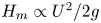 $H_m \propto U^2/2g$. Irrespective of the working liquid, figure 12(b) illustrates that
 $H_m$ is indeed proportional to
 $U^2/2g$ when all data from figure 12(a) are non-dimensionalized in terms of
 $H_m/R$ versus Froude number
 $Fr = U / \sqrt {2g R}$ based on the disc radius. This suggests that the simple ballistic model captures the overall trend and provides a first approximation for the time-averaged inertial sheet height.
Nonetheless, data in figure 12(b) suggest that  $H_m/R \sim Fr$ for all liquids used in our experiments with an
 $\mathcal {O}(1)$ factor that depends on the liquid viscosity. In fact, a closer look at the data makes it clear that
 $H_m$ is significantly smaller than this ballistic height as
 $2 g H_m/U^2 \sim 0.3$, for the case of water. In addition, this ratio seems to decrease at larger speeds. First, the fluid elements which quit the rim before ending up in the sheet do not all have the same momentum and so, the corresponding fluid element may only reach a smaller fraction of the ballistic height
 $U^2/2g$. Second, capillary recession is expected to truncate the liquid sheet when it stretches and thins out, as evidenced by the formation of the liquid rim bordering the liquid sheet on its outer perimeter. Therefore, increasing viscosity is expected to delay this capillary recession, and lead to larger sheets, in accordance with the observed trend.
3.1.2. Time-averaged liquid sheet thickness
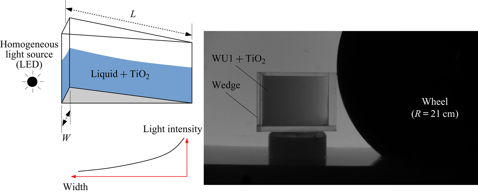
In order to better understand the effect of viscosity on the retardation of the Taylor–Culick cutoff and thereby, explain the larger heights observed when viscosity is increased, further information on the inertial liquid sheet thickness is obtained experimentally. A standard technique is to mix the working liquid with a small amount of fine titanium oxide particles (Ti O $_2$) whereby the liquid opacity increases. For calibration, small wedge-shaped Plexiglass tanks are used (figure 13). When these tanks are filled with opaque liquid/Ti O
 $_2$ mixtures and illuminated with the back light LED panel, the intensity of the light passing through the tank varies depending on the local width. This technique is used to properly calibrate the relationship between liquid thickness and the light intensity received by the camera. It is then possible to deduce the local thickness of the sheet for various wheel immersion depths and rotational speeds. The profiles and contour plots of the mean sheet thickness
 $\delta _s$ are deduced by averaging over
 $1500$ images acquired during 30 s each and then applying this calibration. Data for these time-averaged sheet thickness profiles are depicted in figures 14 and 15. Note that the maximum and the minimum measurable thicknesses are approximately
 $4.5\ \textrm {cm}$ and 2 mm, respectively.
Schematic and photographs showing the wedge used for the calibration of liquid sheet thickness. Two wedges with different lengths and widths were used: (i)  $L = 12.5\ \textrm {cm}$ and
 $W = 4.5\ \textrm {cm}$; (ii)
 $L = 14\ \textrm {cm}$ and
 $W = 1\ \textrm {cm}$. Minimum measurable thickness is 2 mm.

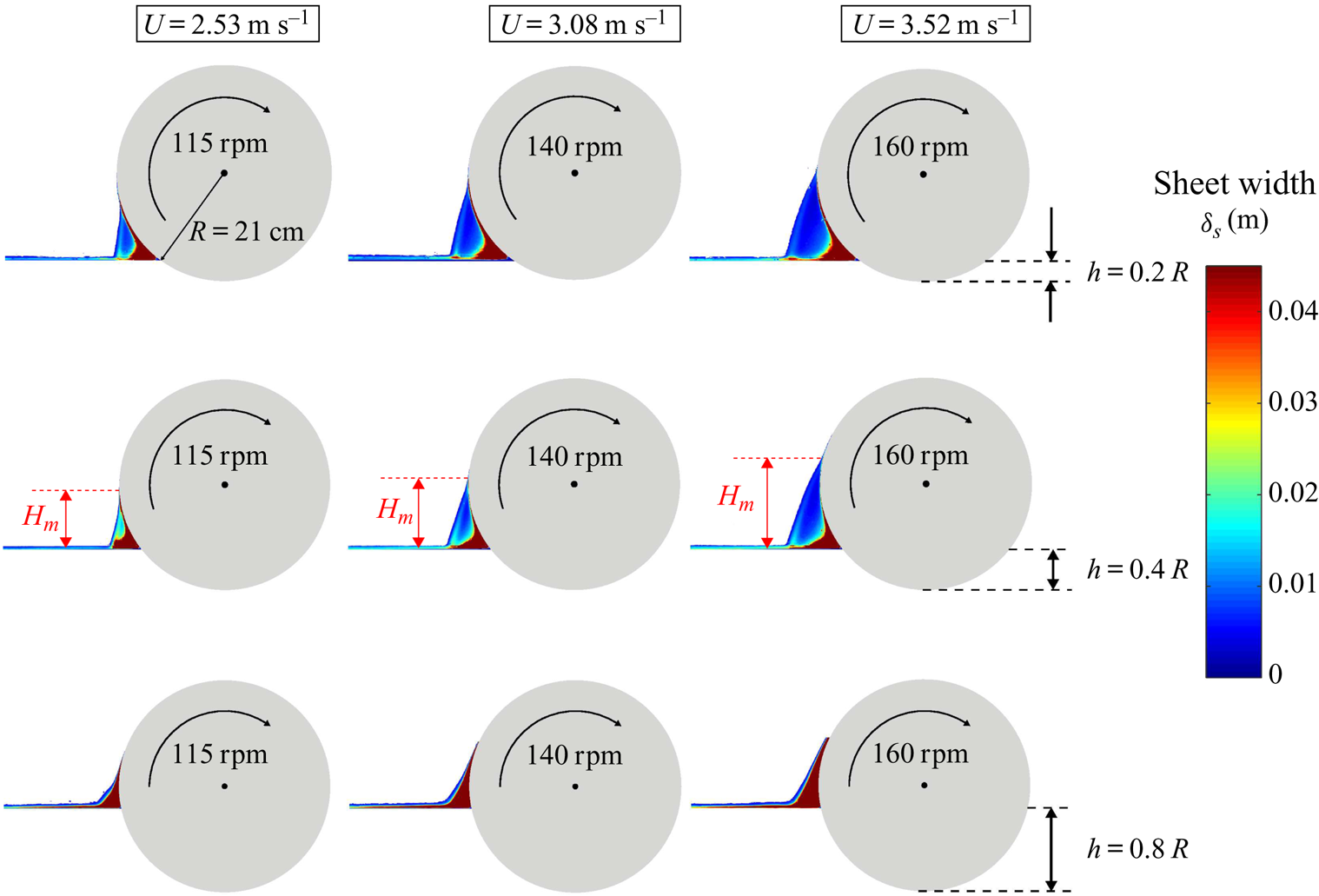
Liquid sheet thickness ( $\delta _s$) at different immersion depth to radius ratios
 ${h/R}$ and rotational speeds for water. All data correspond to a wheel radius of
 $21\ \textrm {cm}$. Maximum measurable thickness is
 $4.5\ \textrm {cm}$ (width of the drum), minimum measurable thickness is
 $2$ mm.

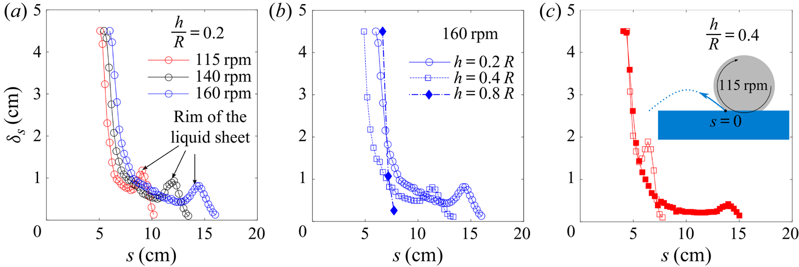
Sheet thickness  $\delta _s$ as a function of the distance
 $s$ travelled along a ballistic trajectory by a hypothetical fluid element that is ejected with an initial velocity equal to
 $U = R \varOmega$ at the emerging side of the wheel (
 $R = 21\ \textrm {cm}$). Here,
 $s = 0$ is at the line of contact between the disc and the horizontal liquid surface.

For both  $h/R = 0.2$ and
 $h/R = 0.4$, the contour plots in figure 14 illustrate that the sheet thickness
 $\delta _{s}$ is not constant. It is thicker than the wheel's rim at its base where fluid elements are ejected with a kinetic energy proportional to
 $U^2/2$, and it rapidly thins out to attain a critical thickness at which capillary recession occurs. This recession then leads to the formation of a thick liquid rim, clearly visible on the thickness profiles. As mentioned previously, this recession leads to sheet truncation at a location where the local fluid velocity is smaller than the Taylor–Culick velocity of
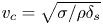 $v_c=\sqrt {\sigma /\rho \delta _{s}}$ (Taylor Reference Taylor1959; Culick Reference Culick1960; Savva & Bush Reference Savva and Bush2009). Thus, for a given water depth, the critical sheet thickness where the sheet forms a thick rim should decrease with increasing rotational speed. This is indeed observed in figure 15(a) wherein
 $\delta _s$ attains a minimum of approximately 2 mm and 4 mm, respectively, as the rotation rate increases from
 $115$ to
 $160$ rpm. On the other hand, at a given rotation rate
 $160$ rpm for both
 $h/R = 0.2$ and
 $h/R = 0.4$, figure 15(b) indicates that
 $\delta _s$ attains a minimum of about the same value
 $4$ mm. So, the depth-to-radius ratio
 $h/R$ only weakly influences this critical sheet thickness where capillary recession leads to truncation. Figure 15(c) compares the measured thickness for both water and a UCON
 $^{\textrm{TM} }$/water mixture at
 $h/R = 0.2$ and a wheel speed of
 $115$ rpm. In comparison, the liquid sheet width decreases in a very similar trend for both cases until the point where a liquid rim is formed for the case of water at approximately
 $s = 7.5\ \textrm {cm}$ and
 $\delta _s \approx 1.5\ \textrm {cm}$ whereas the formation of a liquid rim occurs much later for the UCON
 $^{\textrm{TM} }$/water mixture. In the latter case, the critical sheet thickness
 $\delta _s$ where recession truncates the sheet is approximately
 $0.3\ \textrm {cm}$. This suggests that, compared to the case of water, capillary recession is delayed for the more viscous UCON
 $^{\textrm{TM} }$/water mixture.
Finally, it is pointed out that the contour plots in figure 14 for the case of  $h/R = 0.8$ present a distinct phenomenon. They show that the thickness of the sheet is at least as large as the wheel width for all velocities presented here and it is so almost all over the sheet. Also, no characteristic liquid rim is observed when
 $h/R = 0.8$. This trend is also visible in figure 15(b) where the liquid sheet thickness (filled, blue diamonds) remains thicker than
 $4.5\ \textrm {cm}$ for a good distance away from the wheel and then the sheet suddenly disintegrates without a rim.
3.2. Entrained liquid film
As mentioned in the introductory section, the inertial entrainment produced by a rotating wheel does not only eject a thin liquid sheet, but also drags out a liquid film on the wheel rim. We discuss in the following the flow rate entrained in this liquid film. While it is conventional in the LLD approach to characterize the film thickness  $\delta _f$, a global flow rate measurement is privileged in this study over film thickness measurements for practical reasons. At the same time, this provides a interesting measurement of the ‘efficiency’ of the overall inertial entrainment flux.
Most of the film flow rate measurements were done using a simple scraping technique which consists in applying the sharp edge of a flexible, transparent plastic sheet on the declining side of the wheel rim and thereby scraping the film flow out of the rim. The former is then collected into a large receptacle, including droplets ejected from the film itself for larger rotation speeds. Since disc speed  $U$ can show large variations when one scrapes off the lubrication film, special care was taken to avoid such variations by systematically monitoring the tachometer over the time interval during which the liquid is allowed to flow into the receptacle. This technique showed very good repeatability. It is also possible to use a local measurement technique which measures the film thickness at a given location on the cylinder, as is common at low Reynolds number entrainment flows. However, due to the large Reynolds numbers at the scale of the liquid film, a series of local film thickness measurements using chromatic confocal imaging showed strong spatio-temporal fluctuations of the film thickness at any given point on the rim. In fact, the scraping technique is found to be more robust compared to the local measurement technique as it directly provides a spatio-temporal average of the film flow rate, during a fixed time interval. This time interval was of 40 s for the lowest wheel velocities, but had to be reduced down to 10 s for larger velocities, in order to ensure that the volume of the removed sample does not exceed 2 litres, and that the liquid level in the tank remains constant during the measurement.
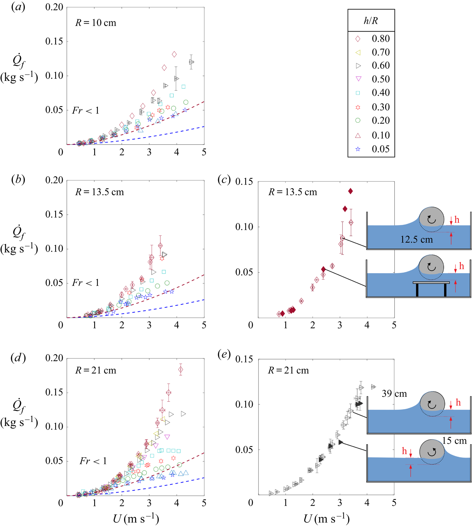
Figure 16 depicts the variations of the time-averaged film flow rate as a function of velocity, measured for the three discs of radius  $R = 10\ \textrm {cm}$,
 $13.5\ \textrm {cm}$ and
 $21\ \textrm {cm}$ over at least seven different immersion heights in water. Data in figure 16 are averaged over different experimental trials for which the rotational speeds differ by at most 5 %. The error bars in this figure represent the standard deviation of measurements in such samples of trials. For the sake of clarity, figure 16 presents these error bars only for a few cases. It shows that the entrained flow rate increases monotonically with the disc speed
 $U = R \varOmega$ and also with the depth
 $h$. Note that all data seem to be relatively independent of the water height
 $h/R$ up to some critical azimuthal speed
 $U$. After this limit, figure 16 clearly indicates that the entrained water flow rate is strongly influenced by the immersion height
 $h$. For example, the film flow rate at
 $h/R = 0.8$ is three times larger than that at
 $h/R = 0.05$ for discs
 $R = 10\ \textrm {cm}$ and
 $13.5\ \textrm {cm}$. And it gets as large as eightfold when
 $R = 21\ \textrm {cm}$.
Time-averaged water flow rate  $\dot {Q}_f$ in the entrained liquid film on the rim of the rotating disc. Dashed blue and red lines represent estimations using (3.2), as provided by Tharmalingam & Wilkinson (Reference Tharmalingam and Wilkinson1978), for respectively the smallest and the largest depth (
 $h/R = 0.05$ and
 $h/R = 0.8$). For the sake of clarity, error bars are given only for one set of data per wheel.

It is well known in dip-coating flows that confinement can play an important role (Kim & Nam Reference Kim and Nam2017) if the meniscus, or the liquid sheet, at the emerging side of the wheel's rim is confined. However, we observe no major effect of confinement in our experiments. We checked this (i) by adding a Plexiglass floor below the wheel, which reduces the distance between wheel and bottom wall from 12.5 cm down to 3 mm (figure 16b,c) and (ii) reversing the wheel's direction of rotation (the distance between the wheel and the wall goes from 39 cm to 15 cm, as in figure 16d,e). In both cases, we could verify that this had no measurable impact on the entrained flow rate.
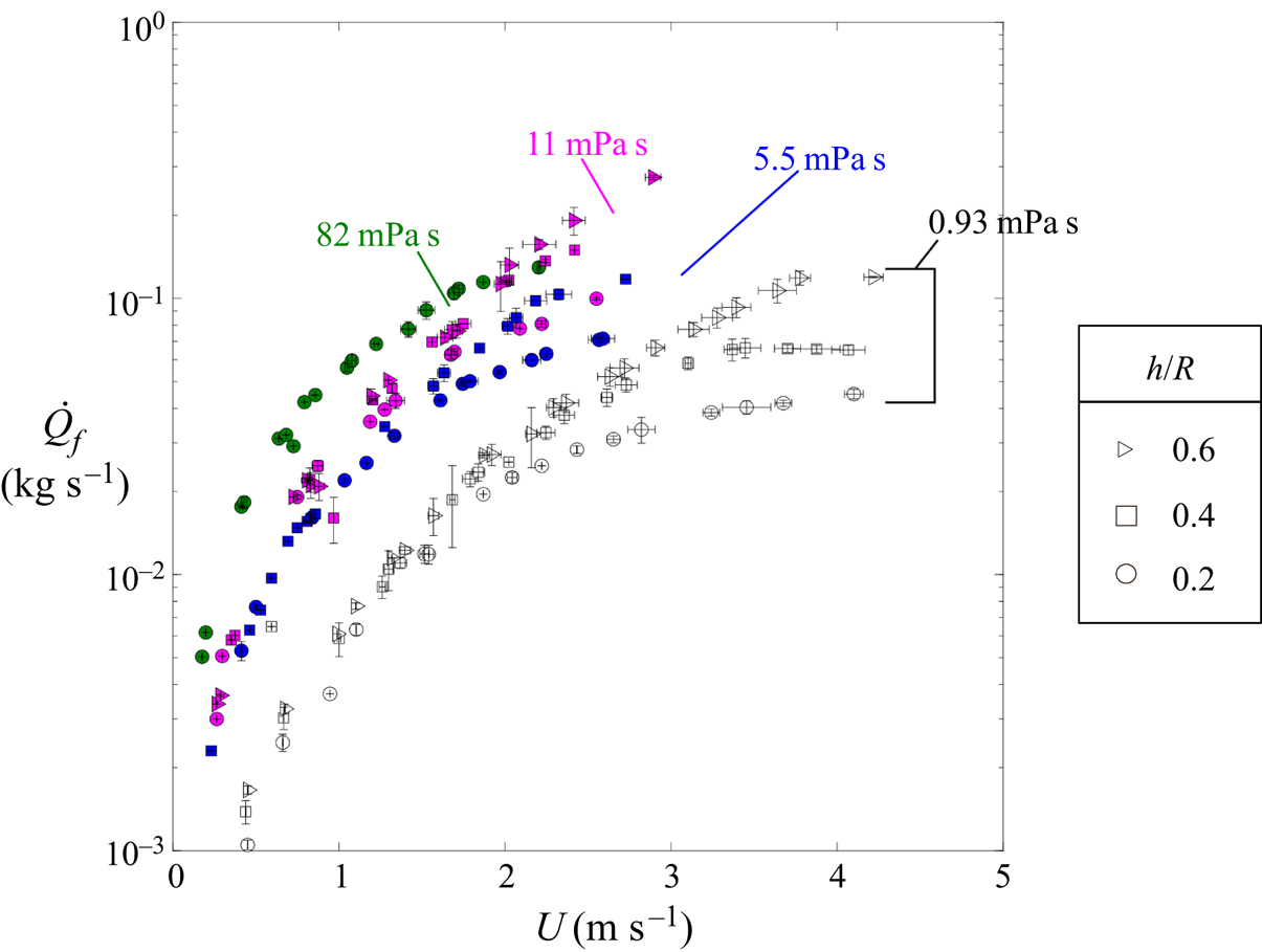
The role of the working liquid is explored using the same various water–UCON $^{\textrm{TM} }$ mixtures as in the previous section. Figure 17 illustrates that, as expected, increasing the liquid viscosity increases the flow rate. Thus, when the liquid viscosity is increased approximately
 $100$-fold, an increase in the liquid entrainment by an order of magnitude is observed. The effect of liquid depth observed for water is also observed for these liquids and, more importantly, figure 17 suggests that the corresponding critical velocity depends on the working liquid.
Impact of viscosity on the entrained flow rate at a fixed disc radius ( $R = 21\ \textrm {cm}$).

3.2.1. Comparison with 2-D creeping flow models
It is conventional in film coating flows to study the entrained flow by monitoring the film thickness  $\delta _f$ as a function of the capillary number
 $Ca = \mu U / \sigma$. In the creeping flow regime (
 $Re \ll 1$), the entrained mass flow rate is then given by
 \begin{equation} \dot{Q}_f = \rho U \delta_f w \left[ 1 - \dfrac{1}{3} \left(\dfrac{ \delta_f}{\delta_f^{g}} \right)^2 \right], \end{equation}
where  $w$ is the rim thickness (Deryaguin & Levi Reference Deryaguin and Levi1964; Groenveld Reference Groenveld1970a). Note that the film flow thickness
 $\delta _f$, at sufficiently small
 $Ca$, should correspond to the expression (1.1) associated with the classical Landau–Levich–Deryaguin dip-coating flow. However, when
 $Ca \gg 1$, previous observations (Ruschak Reference Ruschak1985; Kizito et al. Reference Kizito, Kamotani and Ostrach1999) report that the observed mass flow rate in the entrained film is obtained from the above expression if the film thickness
 $\delta _f$ is taken as in the expression (1.2). This corresponds to the viscosity–gravity driven dip-coating flow and in this case,
 $\dot {Q}_f = 2/3 \times \rho U w \delta _f^{g}$. More recently, Jin et al. (Reference Jin, Acrivos and Münch2005) suggested, via numerical simulations of creeping flow (
 $Re \ll 1$) at sufficiently large capillary numbers, that the right expression for the flow rate with
 $\delta _f = \delta _f^{g}$ should contain a different pre-factor
 $0.58$ instead of
 $2/3$. In order to compare our experimental data with these results, we render the experimental flow rates of figure 17 dimensionless with
 $\dot {Q}_{LLD}$ and
 $\dot {Q}_{G}$:
 $\dot {Q}_{LLD}$ is obtained from expression (3.1) when the film thickness is taken to be
 $\delta _f^{LLD}$ (1.1), whereas
 $\dot {Q}_{G}$ is obtained from the same expression (3.1) but with a film thickness of
 $\delta _f^{g}$ (1.2) so that
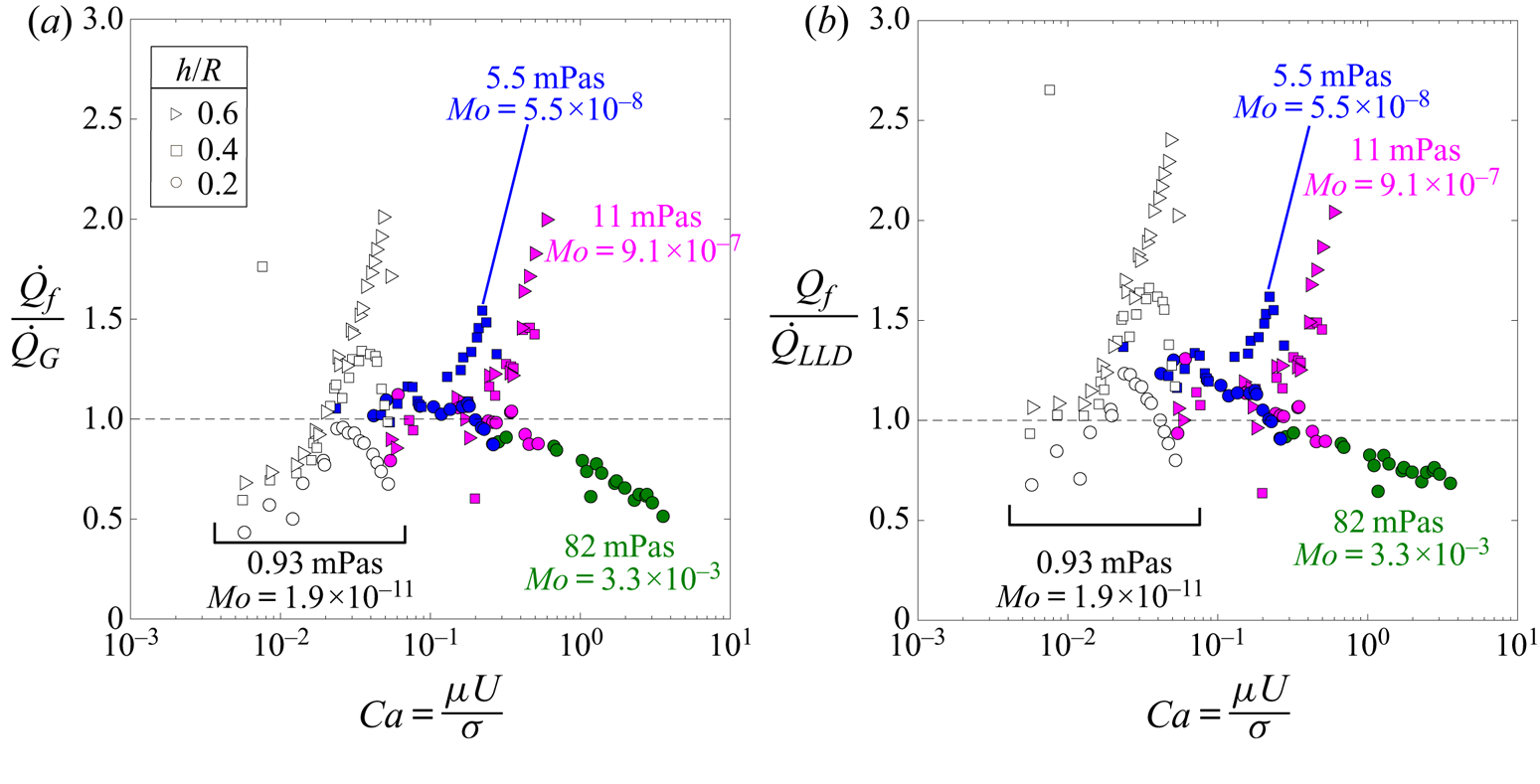
 $\dot {Q}_{G} = 0.58 \times \rho U w \delta _f^{g}$. Figure 18 indicates that both
 $\dot {Q}_{LLD}$ and
 $\dot {Q}_{G}$ capture the correct order of magnitude of the entrained mass flow rate, which, as inferred from figure 17, varies over more than two orders of magnitude. The main dispersion observed in the rescaled experimental data is due to depth-to-radius ratio
 $h/R$. In addition, figure 18 suggest that this dispersion kicks-in at some capillary number which depends on the working liquid's Morton number. Finally, below this characteristic capillary number, the ratio
 $\dot {Q}_f / \dot {Q}_{LLD}$ is approximately equal to unity for all liquids while the ratio
 $\dot {Q}_f / \dot {Q}_{G}$ significantly departs from unity for experiments in water.


In fact, it is already known in coating flows that a transition from the LLD law to an inertia-dominated regime happens when the capillary pressure at the base of the liquid film is no longer large compared to the wall-imposed dynamic pressure  $\rho U^2$. This is precisely the case as the Weber number becomes sufficiently large. Note that two Weber numbers can be defined, depending on the length scale chosen, namely,
 $We_f$ based on the drainage length scale
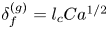 $\delta _f^{(g)} = l_c Ca^{1/2}$ (Kizito et al. Reference Kizito, Kamotani and Ostrach1999) and
 $We_\lambda$ based on the quasi-static LLD meniscus length
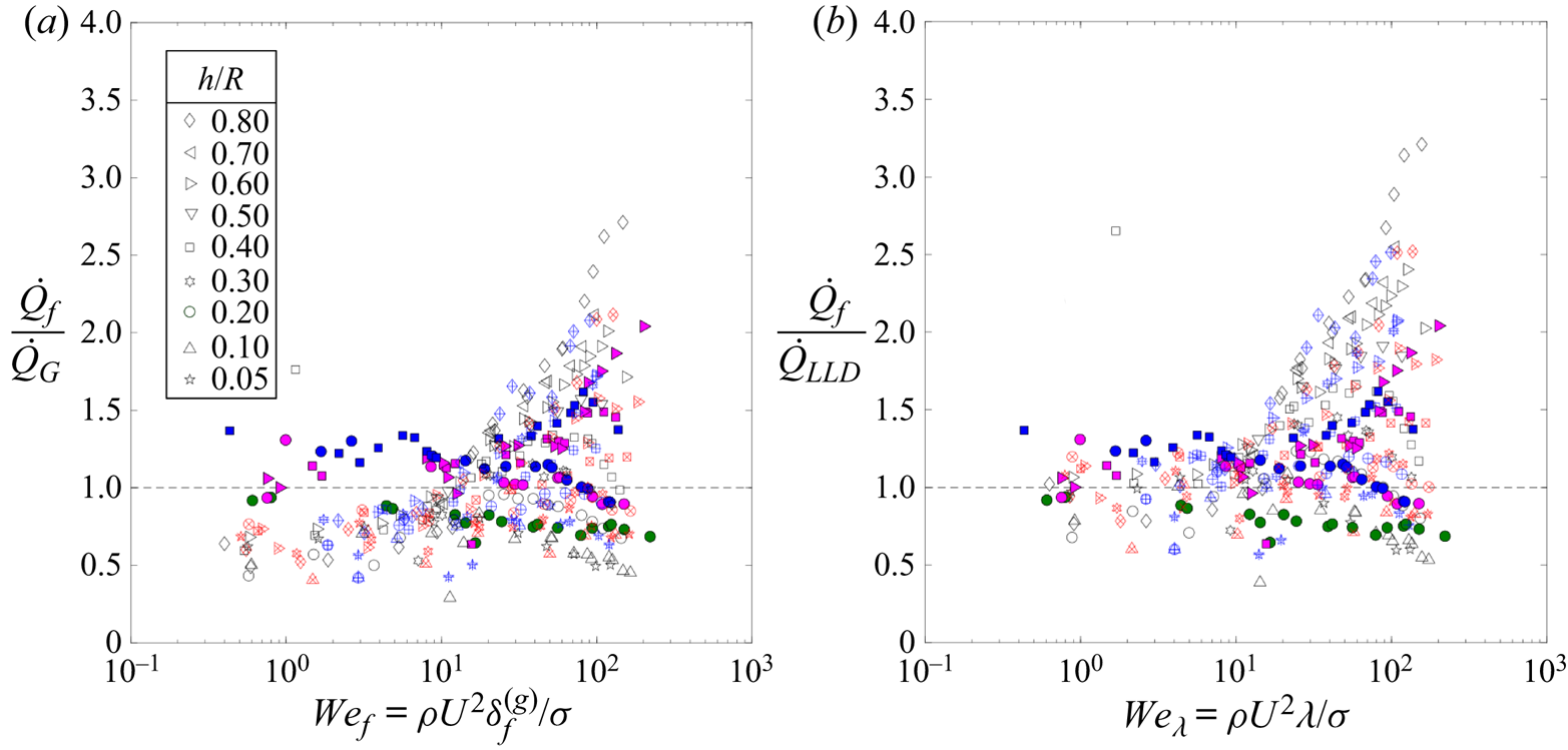
 $\lambda \simeq 0.65 l_c Ca^{1/3}$ (De Ryck & Quéré Reference De Ryck and Quéré1996). We further investigate how the liquid depth modifies the film thickness by plotting all the data from figures 16 and 17 as a function of these Weber numbers in figure 19.
Rescaled data from figures 16 and 17 as a function of Weber number 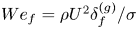 $We_{f} = \rho U^2 \delta _f^{(g)} / \sigma$ (a) and
 $We_{\lambda } = \rho U^2 \lambda / \sigma$ (b) based on the LLD dynamic meniscus length
 $\lambda = 0.65 l_c Ca^{1/3}$, where
 $l_c = \sqrt {\sigma / \rho g}$ is the capillary length. Here, open symbols with
 $+$ (red online) and
 $\times$ (blue online) represent experimental results for
 $R = 10\ \textrm {cm}$ and
 $R = 13.5\ \textrm {cm}$, respectively.

There is a relatively good collapse of data for Weber numbers smaller than  $10$, in particular when these data are plotted as a function of
 $We_\lambda$. In addition, the effect of wheel depth
 $h$ which kicks in at strikingly different capillary numbers in figure 18 (ranging from
 $10^{-2}$ to
 $1$) appears above a single threshold Weber number of approximately
 $10$, both for
 $We_\lambda$ and
 $We_f$. To the authors’ knowledge, this is the first ever demonstration of the existence of such a characteristic Weber number above which a transition occurs from 2-D creeping flow to an inertial regime for rotary film entrainment. Beyond this Weber number the film thickness is either under-estimated or over-estimated by both the LLD dip-coating law and drainage film length, depending essentially on the ratio
 $h/R$.
Note that the rotary flow entrainment problem in our case is particularly distinct from that of classical coating flow processes. Here, instead of a dynamic LLD meniscus at the base of the liquid film flow, a large, corrugated liquid sheet is present due to inertial ejection of the liquid at the emerging side of the disc's rim. As already illustrated in § 3.1, the latter presents a three-dimensional flow structure and its height is proportional to the square of the Froude number. Moreover, the range of Reynolds numbers 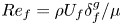 $Re_f = \rho U_f \delta _f^g / \mu$ in the film flow varies between
 $\mathcal {O}(1)$ and
 $\mathcal {O}(10^{3})$. Therefore, it is quite unexpected that a good agreement with 2-D creeping flow analyses is retrieved here for the entrained flux on a rotating disc, as long as
 $We_{\lambda } < 10$. In addition, this model provides a satisfactory order of magnitude for the film flow rate even when
 $We_{\lambda } > 10$.
3.2.2. Impact of depth on entrained flow rate when  $We_{\lambda } > 10$

Figures 16(a–e) and 17 suggest that beyond a critical speed the role of depth must be accounted for. In this context, Tallmadge (Reference Tallmadge1971) and Tharmalingam & Wilkinson (Reference Tharmalingam and Wilkinson1978) suggested a suitably modified version of the dip-coating flow (see schematic figure 6c). In fact, via lubrication approximation along with LLD-type asymptotic analysis, these authors previously predicted that the average mass flow rate should be
 \begin{equation} \dot{Q}_{TT} = \rho U \delta_f w \left[ 1 - \dfrac{1}{3} \left(\dfrac{ \delta_f}{\delta_f^{g}}\right)^2 \sin \alpha \right], \end{equation}
where  $\delta _f$ is computed from expression (1.4) and
 $\alpha$ is the angle between the tangent to the partially immersed cylindrical drum at its line of contact with the liquid bath at rest and the horizontal line. When the measured data are compared with the estimates from this model (dashed blue and red lines in figure 16), a reasonable qualitative agreement is observed, showing a strong relative increase in the flow rate with increasing depth. This arises from the fact that the model accounts for the squeezing of the meniscus occurring at large
 $\alpha$, or low depths, and therefore predicts a smaller flow rate than that of (1.1) corresponding to the drag-out problem of a vertical plate (
 $\alpha = 90^{\circ }$). Nevertheless the model largely underestimates the entrained flow rate. Also,
 $\dot {Q}_{TT}$ depends on
 $h/R$ irrespective of the wheel speed
 $U$ while figures 16(a–e) and 19 suggests that, for all
 $We_\lambda < 10$, the entrained flux is well predicted by the classical 2-D creeping flow models corresponding to the vertical drag-out problem. Therefore, the observed influence of depth
 $h$ when inertia dominates both surface tension and viscous forces (i.e. at large
 $Re_f$ and
 $We_{\lambda }$) cannot be explained by simply accounting for the angle between the emerging side of the disc and the horizontal pool level in the LLD flows.
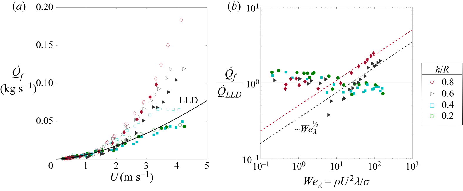
A first possible explanation can be found in the observation that there exists a thin liquid film which is dragged out of the liquid bath by the disc's lateral walls and which could, in turn, contribute to the film flow on the disc's rim provided that centrifugal forces overcome gravity, which occurs for  $Fr>1$. This contribution is expected to increase when the depth is increased and a larger fraction of the lateral wall is consequently wet. In order to better quantify this contribution, two wiper blades were used to scrap off the lateral film: the wiper blades were placed right next where the disc's lateral walls and the liquid bath meet. The results are shown in figure 20 for
 $R = 21\ \textrm {cm}$ at various water depth
 $h/R$ (filled symbols) where they are also compared with data from figure 16(d,e). Here, it is evident that the water flow on the lateral wall modifies the entrained flow on the rim. Clearly, data from experiments with lateral scrapping for the case of
 $h/R = 0.2$ and
 $h/R = 0.4$ closely follow a unique curve given by
 $\dot {Q}_{LLD}$. Nonetheless, at water depths corresponding to
 $h/R = 0.6$ and
 $0.8$, the supplementary entrainment via lateral walls accounts only for approximately 10 %–20 % increase in film flow rate on the disc's rim. Furthermore, experimental data in figure 20(b) strongly suggest that, for both
 $h/R = 0.6$ and
 $h/R = 0.8$, the entrained flow rate in the absence of contribution from the film flow along lateral walls increases as a power law of
 $We_{\lambda }$, independent of
 $h/R$.
Direct evidence for the contribution from liquid entrained via lateral walls (water, and wheel radius  $R = 21\ \textrm {cm}$). Open symbols represent the cases without lateral scrapping while closed symbols represent data from scrapped cases. Remarkably, data corresponding to the depth to radius ratio
 $h/R = 0.4$ (black, filled squares) follow the LLD scaling when lateral entrainment is scrapped off. However, for
 $h/R = 0.6$ and
 $0.8$, lateral entrainment cannot completely explain the increase in mass flow rate.

The physical mechanism for this observed entrained flux augmentation at depth-to-radius ratio  $h/R > 0.4$ can be linked with the shape and dynamics of the liquid sheet on the emerging side of the wheel. As illustrated via photographs figure 9 and time-averaged sheet thickness measurements figure 14 in § 3.1, when the water depth is sufficiently large, the whole liquid sheet is as thick as the wheel rim whereas the sheet thickness is negligibly small compared to the wheel width when
 $h/R \leq 0.4$. In the latter case, it is deduced that the liquid sheet does not influence the flow rate at all speeds, whatever the working Weber number
 $We_\lambda$, as depicted by the corresponding data in figure 20(b) in the absence of any contribution from lateral wall entrainment. However, in the former case, i.e. when
 $h/R > 0.4$, the liquid sheet wets the entire thickness of rotating wheel: liquid is entrained from this liquid rim onto the wheel. Taking this action of the liquid sheet into account, it is possible to extend the classical Landau–Levich scaling to explain the liquid entrainment without lateral wall contributions.
In the classical entrainment problem, as illustrated by Maleki et al. (Reference Maleki, Reyssat, Restagno, Quéré and Clanet2011), Landau–Levich asserted that the viscous driving force per unit volume  $\mu U/\delta _f^2$ on a fluid element is balanced out by the restoring force per unit volume
 $(\sigma / l_c)/ \lambda$ which is taken solely due to the pressure gradient arising from the Laplace pressure across the dynamic meniscus of length
 $\lambda$. Here,
 $\delta _f$ is the entrained film thickness and
 $l_c = \sqrt {\sigma /\rho g}$ is the capillary length. The missing length scale
 $\lambda$ is then obtained by matching the curvature of the dynamic meniscus
 $\delta _f / \lambda ^2$ to the static curvature
 $1/l_c$. Thereby, it is possible to obtain
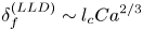 $\delta _f^{(LLD)} \sim l_c {Ca}^{2/3}$ which is exactly the first-order approximation to the Wilson formula in (1.1). However, the fact that the wheel rim is entirely covered by a thick liquid sheet from which the thin liquid film emanates is indeed very distinct from the Landau–Levich case wherein the liquid film emerges from a quasi-static liquid bath. Therefore, it is no longer appropriate to match the curvature of dynamic menisci
 $\delta _f / \lambda ^2$ with those of static menisci
 $1/l_c$. Since the sheet height
 $H_m$ depends only weakly on the wheel radius
 $R$, a simple dimensional analysis points out that the appropriate curvature before the dynamic meniscus should be
 $g/U^2 \times f(h/R)$. By matching the curvature of the dynamic meniscus
 $\delta _f / \lambda ^2$ with this inertial meniscus curvature, the film thickness
 $\delta _f^{I}$ is obtained as
 \begin{equation} \delta_f^{I} \sim l_c {Ca}^{2/3} \left(\dfrac{U^2}{g l_c} \right)^{1/3} \zeta\left(\dfrac{h}{R} \right), \end{equation}
where  $\zeta (h/R)$ is an arbitrary function of only the water depth to radius ratio. Thus, the corresponding entrained film flow rate is given by
 \begin{equation} \dot{Q}_f^{I} \sim \dot{Q}_f^{LLD} We_{\lambda}^{1/3} Ca^{{-}1/9} \zeta\left(\dfrac{h}{R} \right). \end{equation}
where only the first-order contribution of the thickness (1.1) in the expression (3.1) is taken. The modified LLD scaling (3.4) can be compared with the experimental data for the case when the liquid sheet occupies the entire rim i.e. when  $h/R \geq 0.6$. As seen in figure 20(b), despite many simplifying assumptions, the above scaling argument matches relatively well with the available data when the contribution from lateral entrainment is scrapped off for both
 $h/R = 0.6$ and
 $h/R = 0.8$. Therefore, up to a first estimate, the observed entrainment in the inertial regime of a rotating wheel at
 $h/R\ge 0.6$ should arise from the presence of a thick liquid sheet.
4. Conclusion
The aim of the present work is to illustrate the dominant flow structures in relation to the rotary entrainment of a partially submerged disc in the absence of any confinement at the point where the disc emerges out of the liquid pool. In particular, we performed experiments in the range of very large Reynolds  $Re_f$ and Weber numbers
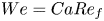 $We = Ca Re_f$ where the relevant Reynolds numbers is taken as
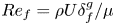 $Re_f = \rho U \delta _f^{g}/\mu$ with the drainage length scale
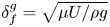 $\delta _f^{g} = \sqrt {\mu U/ \rho g}$.
Experiments showed that a liquid sheet of finite height is present on the emerging side of the rotating disc when the rotational speed is sufficiently large ( $U \gtrsim 0.8\ \textrm {m}\ \textrm {s}^{-1}$). The time-averaged liquid sheet height
 $H_m$ is shown to be proportional to the maximum ballistic height
 $U^2/2g$ attained by a fluid particle. It is independent of the immersion depth
 $h/R$, except for the case of
 $h/R \geq 0.6$ wherein combined immersion depth and the sheet height become larger than the wheel size
 $h + H_m > R$. In particular, when the immersion depth is small compared to the radius (
 $h/R < 0.5$), time-averaged sheet thickness measurements indicate that the sheet rapidly thins out until capillary recession inhibits further decrease. Since the capillary recession is delayed in viscous liquids, the sheet height in viscous UCON
 $^{\textrm{TM} }$/water mixtures is found to be much larger than those observed in water at the same velocity. For large depth-to-radius ratio
 $h/R$, no capillary recession is observed. Instead a thick liquid sheet as large as the rotating wheel's rim appears which in turn can influence the entrained liquid flux over the rim of the rotating disc.
Despite  $Re_f \gg 1$ ranging over three decades in the present experiments, the liquid entrainment follows remarkably the flow rates predicted by the 2-D creeping flow models until a characteristic capillary number
 $Ca = \mu U / \sigma$, or equivalently a characteristic Reynolds number, depending only on the liquid physical properties (since
 $Re_f = \sqrt {Ca^3/Mo}$ where the Morton number
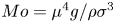 $Mo = \mu ^4 g / \rho \sigma ^3$). The transition to an inertia-dominated entrainment regime occurs when the capillary pressure based on the quasi-static LLD meniscus length
 $\lambda \simeq 0.65 l_c Ca^{1/3}$ becomes lesser than the wall-imposed dynamic pressure
 $\rho U^2$. Experimental data in the present study demonstrate that such a transition happens when
 $We_\lambda = \rho U^2 \lambda / \sigma$ is approximately
 $10$. Beyond this limit, two major contributions are identified for inertial entrainment: (i) lateral wall entrainment and (ii) entrainment from the top of the thick liquid sheet. The former is present when the Froude number based on the wheel radius is larger than unity and at this stage, the liquid film entrained on the lateral wall is centrifuged towards the wheel rim. This seems to be the dominant mechanism when the water depth is small compared to the wheel radius. The latter modifies the curvature of the quasi-static liquid in front of the entrained film and thereby leads to an enhanced film flow rate. This contribution is predominant when the liquid sheet thickness is comparable to that of the wheel's rim (
 $h/R > 0.5$).
We also showed, however briefly, that sheets can meander, become corrugated and fragment into droplets. Furthermore, when the disc width is increased multiple sheets can occur. While internal/external rimming flows and rotary coating flows have received a lot of attention in the last few decades (Seiden & Thomas Reference Seiden and Thomas2011; Schweizer & Kistler Reference Schweizer and Kistler2012), not much is known for the case of a rotating cylinder submerged in liquid pool in the absence of confinement at the emerging side of the cylinder. So, the authors hope that the present work motivates further numerical simulations and experiments on the complex flow structures occurring in inertia-dominated liquid film flows and also, in the more challenging fully 3-D two-phase flow problem of rotary entrainment at large Reynolds numbers and Weber numbers.
Acknowledgements
The authors acknowledge S. Martinez and A. Buridon for their technical assistance, H. Scolan and also the contribution from projects at the Mechanics department in the Université Claude Bernard Lyon $1$ for several measurements. Financial support from
 $Groupe$
 $PSA$ is also acknowledged by the authors.
Declaration of interests
The authors report no conflict of interest.
Supplementary movies
Supplementary movies are available at https://doi.org/10.1017/jfm.2020.879.
Dimensionless numbers as inferred from previous entrainment flow studies: RD – rotating drum, RMC – rotary/meniscus coating, e/iRF – external/internal rimming flows, FC – flat plate (vertical/inclined) dip coating. GS – golden syrup, P – paraffin, S – silicone oil, LO – linseed oil, WG – water/glycerin mixtures, WT – water/Triton CF-10, WU – water/UCON mixtures, NS – numerical simulations.