I. INTRODUCTION
Nanocrystalline materials generally exhibit superior strength but at the expenses of low tensile ductility and low fracture toughness, which have been considered to be crucial factors limiting their practical utility. Reference Ovid'ko1–Reference Gerberich, Michler, Mook, Ghisleni, Östlund, Stauffer and Ballarini3 In particular, compared with conventional microcrystalline materials, low fracture toughness of nanocrystalline solids is highly undesired for structural applications, and thus toughening of nanocrystalline metals is emerging. Reference Kuntz, Zhan and Mukherjee4–Reference Liu, Zhou, Shen and Hui7 Hence, much research has been undertaken in understanding the fundamental laws governing the process of crack growth, as well as ductility and strength behaviors in nanocrystalline materials. Reference Ovid'ko, Skiba and Mukherjee8–Reference Zhao, Topping, Bingert, Thornton, Dangelewicz, Li, Liu, Zhu, Zhou and Lavernia12
In nanocrystalline or ultrafine-grained materials, dislocations emitted from a crack tip glide along one slip plane, stop at opposite grain boundaries (GBs) and eventually suppress the emission of subsequent dislocations, which is the most typical process for blunting of the crack. Reference Ovid'ko and Sheinerman13 Therefore, emissions of dislocations from a crack tip and their effects on fracture toughness in nanocrystalline materials have been widely investigated. Reference Ovid'ko and Sheinerman14–Reference Feng, Fang, Zhang and Liu16 Within the descriptions of Ovid'ko and Sheinerman, Reference Ovid'ko and Sheinerman14 stress fields of these previous dislocations will suppress generation of subsequent dislocations from the crack, and this suppression depends on grain size of nanocrystalline and ultrafine-grained materials. On that basis, the hindrance of crack blunting on emission of further dislocations from a crack has also been incorporated. Reference Ovid'ko and Sheinerman13 In addition, theoretical models are suggested to describe influence of intergrain sliding on crack growth. Reference Bobylev, Mukherjee, Ovid'ko and Sheinerman17 Liu et al. Reference Liu, Zhou, Wang, Zhang and Wang15 have demonstrated that the combined effects of the aforementioned two deformation mechanisms, i.e., generation of edge dislocations from crack tips and intergrain sliding, lead to an increase of critical crack intensity factor. In addition, the roles of nano-metal particles Reference Liu, Zhou and Shen18 and interactions between dislocations and GBs Reference Wang, Zhou, Zhang, Liu and Dong19 in fracture toughness of materials have also been studied. A common conclusion is shared in these models that fracture toughness decreases with grain size refinement due to the fact that gliding paths of emitted dislocations become shorter for smaller grain. Reference Ovid'ko and Sheinerman14
Recently, efforts have been made to overcome the low tensile ductility and low fracture toughness of nanocrystalline materials through microstructural controls, and composites have been thought to be a breakthrough. Reference Ye, Han, Lee, Ahn, Nutt and Schoenung20,Reference Li, Zhao, Ortalan, Liu, Zhang, Vogt, Browning, Lavernia and Schoenung21 As a type of extraordinary reinforcement, carbon nanotubes (CNTs) possess exceptional mechanical properties Reference Zhao, Jiang, Wang, Guo and Rabczuk22,Reference Zhao, Lu and Rabczuk23 and hold great promise for employing in different metal matrices. Reference Li and Tian24–Reference Dong, Zhou, Liu and Qi30 By choosing the right combinations of metal matrix and the reinforcement, composites with expected strength and ductility can be achieved. Reference Xue, Wang, Zhao, Xu, Qi and Fei31,Reference Borkar, Hwang, Hwang, Scharf, Tiley, Hong and Banerjee32 The fracture toughness of nano/ultrafine-grained composite containing 2.0 vol% single-walled carbon nanotubes (SWCNTs) was observed to be higher than that of pure nanocrystalline and ultrafine-grained metal matrix by a factor of 1.44, and 1.31, Reference Choi and Bae33 respectively. SWCNTs was thought to effectively block the propagation of cracks and provide much enhanced ductility and toughness. Reference Choi and Bae33 Recently, Jiang et al. Reference Jiang, Li, Fan, Cao and Zhang34 have prepared CNTs/Al nanolaminated composites by flake powder metallurgy and observed that final bulk products exhibit greatly enhanced plasticity of 12%. They attributed the phenomenon to enhanced dislocation storage capability and two-dimensional alignment of the reinforcement.
The presence of CNTs can greatly modify microstructures of matrix, which may in turn play a more significant role in mechanical properties of composites than actual presence of the reinforcement. Reference Curtin and Sheldon35,Reference Dong, Zhou, Hui, Wang and Zhang36 Therefore, the physics nature of fracture process of these nanocomposites has been the subject of intensive studies, Reference Gutkin and Ovid'ko37 and a number of toughening mechanisms have been suggested, such as crack deflection, bridge-toughening mechanism, as well as fracture behaviors of the reinforcement. Reference Viet and Kuo38 In CNTs-reinforced metal matrix composites (MMCs), crack propagation can be retarded by pulling forces of the reinforcement, i.e., bridge-toughening mechanism. CNTs/matrix interface strength and interface length are significant factors affecting fracture toughness of hard/soft matrix composites, and their effects have been evaluated by a hierarchical analysis based on atomistic simulation, fracture mechanics, and shear-lag theory. Reference Chen, Liu, Huang and Hwang39,Reference Chen, Liu, He, Huang and Hwang40 It is found that neither stronger interface strength nor longer interface length can definitely lead to better fracture toughness. In addition, increasing the length of CNTs beyond 100 nm does not lead to further improvement of fracture toughness.
The mobility and stability of dislocations in MMCs can significantly affect mechanical responses of these composites. Reference Goh, Wei, Lee and Gupta41 Gutkin and Ovid'ko Reference Gutkin and Ovid'ko37,Reference Gutkin and Ovid'ko42 have described the glide of hollow fibers (CNTs, in particular) at the bridging stage of fracture by generation of nanoscale dislocation loops in ceramic matrix nanocomposites. The emphasis of these studies lies on determination of critical stress required for nucleation of first dislocation loop and calculation of energy characteristics in this process. It is shown that critical stress is tightly related with fiber wall thickness and shear moduli of matrix and the reinforcement. In addition, the propagation of a crack tip in aligned CNTs-reinforced nanocrystalline MMCs is also an essential issue to understand toughening mechanisms of these composites. The attention has already been paid on dislocations gliding along the plane that intersects the nanotube cross-section. Reference Dong, Zhou, Hui, Pang, Wang, Zhang and Wang43 In present paper, glide of edge dislocations along interfaces between aligned reinforcement and nanocrystalline matrix will be highlighted.
Here, a theoretical model is proposed to discuss the effect of aligned CNTs on mobility and stability of dislocations emitted from a preexisted crack tip in MMCs. The dependences of critical shear stress, maximum numbers, and equilibrium positions of dislocations on microstructures and orientation angles of aligned reinforcement are evaluated in detail. In addition, the variations of fracture toughness of the composites with orientation angle and gliding distance are also addressed.
II. EFFECT OF INTERACTION BETWEEN DISLOCATIONS AND ALIGNED CNTS ON FRACTURE TOUGHNESS
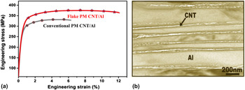
It is observed that dense nanocomposites fabricated by flake powder metallurgy exhibit greatly enhanced plasticity of 12% in comparison with the composites prepared by conventional powder metallurgy, as given in Fig. 1(a). In the nanocomposites, the matrix platelets with aligned CNTs are found to be organized with the faces parallel to the direction of extrusion. Reference Jiang, Li, Fan, Cao and Zhang34 The structure of extruded multilayer with alternating Al (∼400 nm) and CNT layer (∼50 nm) has been clearly observed, as shown in Fig. 1.
(a) Tensile properties of CNTs/Al nanocomposites fabricated by conventional powder metallurgy and flake powder metallurgy Reference Jiang, Li, Fan, Cao and Zhang34 ; (b) A transmission electron microscopy image of CNTs/Al nanolaminated composites fabricated by flake powder metallurgy. Reference Jiang, Li, Fan, Cao and Zhang34

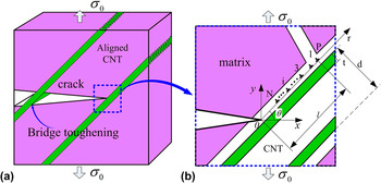
Inspired by the experimental image, we will discuss the effect of interactions between dislocations and aligned CNTs on fracture toughness in nanocrystalline and ultrafine-grained MMCs. Let us consider a long, flat crack grown in aligned CNTs-reinforced MMCs, and the crack intersects aligned CNTs on a straight line. The three-dimensional schematic morphology of aligned CNTs-reinforced MMCs is shown in Fig. 2(a). A typical two-dimensional fragment of the composite consisting of nanoscale grains divided by GBs and partial aligned CNTs with the diameter d and wall thickness t is adopted from Fig. 2(a) and schematically shown in Fig. 2(b). In nanocrystalline metal matrix, emission and gliding of lattice dislocations in grain interiors (GIs) are suppressed. Reference Koch44 Meanwhile, pervasiveness of CNTs at GBs of metal matrix is presented. Reference Kwon, Estili, Takagi, Miyazaki and Kawasaki45,Reference Vasiliev, Poyato and Padture46 Since this kind of distribution of the reinforcement makes the boundaries mechanically weak, fracture will prefer to occur along GBs rather than within GIs. Reference Vasiliev, Poyato and Padture46 Therefore, GB dislocations are assumed to be emitted at the interfaces between metal matrix and aligned reinforcement, and lattice dislocations in GIs are neglected. In addition, the crack is supposed to propagate in the x-axis positive direction under a given tensile load, and gliding plane of GB dislocations along aligned reinforcement inclines angle θ to the positive direction of x-axis.
Aligned CNTs-reinforced MMCs with a long and flat crack. (a) Three-dimensional schematic illustration of toughening mechanisms in these composites; (b) A two-dimensional magnified inset of the part in the dashed area presented in (a) shows emission of edge dislocations from a crack tip with their Burgers vectors parallel with aligned CNTs, and these dislocations finally stop at a distance from the crack tip.

In nanocrystalline matrix composites, the first dislocations emitted from the crack tip is assumed to be retarded at position P, away from the crack tip by distance l and can lead to dislocation pile-ups, as shown in Fig. 2(b). For a given applied tensile load σ0 and gliding distance l, there exists a maximum number N of dislocations in the pile-ups. Reference Mao and Li47
After the first dislocation emitted from a crack tip, the subsequent dislocations must overcome the gliding resistance under the applied load, and eventually assume equilibrium positions. The equilibrium position of the ith dislocation can be determined by the force balance equation
 ${F_i} = b\sigma _{r\theta }^{\rm{e}}\left( {{r_i},\theta } \right) = 0$
,
Reference Ovid'ko and Sheinerman14
where r
i
is the distance between the ith dislocation and the crack tip in a polar coordinate system.
 $\sigma _{r\theta }^{\rm{e}}\left( {{r_i},\theta } \right)$
is the effective stress acting on the ith dislocation and consists of four forces: (i) resolved applied shear stress
 $\sigma _{r\theta }^{\rm{a}}\left( {{r_i},\theta } \right)$
; (ii) image stress
 $\sigma _{r\theta }^{{\rm{im}}}\left( {{r_i},\theta } \right)$
; (iii) elastic stress
 $\sigma _{r\theta }^{{\rm{elastic}}}\left( {{r_i},\theta } \right)$
and (iv) pile-up stress
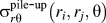
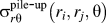 $\sigma _{r\theta }^{{\rm{pile - up}}}\left( {{r_i},{r_j},\theta } \right)$
, which can be summarized as:
 $$\sigma _{r\theta }^{\rm{e}}\left( {{r_i},\theta } \right) = \sigma _{r\theta }^{\rm{a}}\left( {{r_i},\theta } \right) + \sigma _{r\theta }^{{\rm{im}}}\left( {{r_i},\theta } \right) + \sigma _{r\theta }^{{\rm{elastic}}}\left( {{r_i},\theta } \right) <$$><$$>+ \sigma _{r\theta }^{{\rm{pile - up}}}\left( {{r_i},{r_j},\theta } \right)\quad .$$
Now the four stresses will be expressed clearly in the following part. First, the resolved applied shear stress
 $\sigma _{r\theta }^{\rm{a}}\left( {{r_i},\theta } \right)$
is induced by the constant external tensile load σ0 near the crack tip, and written as
Reference Lin and Thomson48
:
 $$\sigma _{r\theta }^{\rm{a}}\left( {{r_i},\theta } \right) = {{K_{\rm{I}}^{\rm{\sigma }}\,\sin \,\theta \,\cos \left( {{\theta \mathord{\left/ {\vphantom {\theta 2}} \right. \kern-\nulldelimiterspace} 2}} \right)} \over {2\sqrt {2\pi {r_i}} }}\quad ,$$
here,
 $K_{\rm{I}}^{\rm{\sigma }}$
is the intensity factor for the applied stress.
The image stress
 $\sigma _{r\theta }^{{\rm{im}}}\left( {{r_i},\theta } \right)$
is associated with the existence of crack surface, and corresponds to image force created by interaction between emitted dislocations and the surface. Here, according to Ref. Reference Lin and Thomson48, the image stress is given:
 $$\sigma _{r\theta }^{{\rm{im}}}\left( {{r_i},\theta } \right) = - {{{G_1}b} \over {4\pi \left( {1 - {\nu _1}} \right){r_i}}}\quad ,$$
where b is the magnitude of Burgers vector of edge dislocation. Metal matrix and the reinforcement are assumed to be elastically isotropic along the sliding direction of dislocations and characterized by Poisson's ratio ν1, ν2 and shear modulus G 1, G 2, respectively.
The elastic stress
 $\sigma _{r\theta }^{{\rm{elastic}}}\left( {{r_i},\theta } \right)$
is created by the difference of shear modulus between the reinforcement and metal matrix. Since rigorous analytical calculation of elastic stress
 $\sigma _{r\theta }^{{\rm{elastic}}}\left( {{r_i},\theta } \right)$
in this model given in Fig. 2(b) is difficult, here we only consider the special case that the diameter of CNTs is far larger than its wall thickness. The assumption is readily applied to CNTs-reinforced MMCs. In this case, inside surfaces of aligned reinforcement are close to dislocation lines and supply a strong screening effect on elastic fields of these dislocations. Then the model can be simplified as straight edge dislocations placed in the interface between a thin layer (wall of aligned CNTs) and a semiinfinite substrate (nanocrystalline metal matrix). Therefore, a simplified planar model can be adopted to estimate the elastic stress field of edge dislocations located in thin two-phase plates with different elastic moduli. If the thickness of matrix is taken to be infinite, and edge dislocations are situated on the interface between aligned CNTs and the matrix, with their Burgers vectors parallel with the aligned reinforcement, then the stress at the interface can be obtained by adopting expressions derived in Refs. Reference Gutkin and Ovid'ko42 and Reference Gutkin and Romanov49:
 $$\sigma _{r\theta }^{{\rm{elastic}}}\left( {{r_i}{\rm{,}}\theta } \right) = {{{G_1}b} \over {4\pi \left( {1 - {\nu _1}} \right)}}\left\{ {{{A\left( {{{\sin }^2}\,\theta - {{\cos }^2}\,\theta } \right) - 2B\,{{\cos }^2}\,\theta + 4\,{{\cos }^2}\,\theta + B - 2} \over {{r_i}}}} \right. - \left. {\int_0^{ + \infty } {f\left( {s,t,A,B} \right)\sin \left( {s{r_i}\sin \,\theta } \right){\rm{d}}s} } \right\}\quad .$$
With thickness of layer taken into consideration, the second term in above equation can be adopted to describe the screening of elastic field of dislocations by inner surfaces of aligned reinforcement. In Eq. (4), the function f(s, t, A, B) is expressed as:
 $$f\left( {s,t,A,B} \right) = {{{{\rm{e}}^{ - 4st}}\left[ {\left( {1 + AB} \right)\left( {A + B} \right)} \right] - 2{{\rm{e}}^{ - 2st}}\left[ {2{{\left( {1 - A} \right)}^2}{s^2}{t^2} - \left( {1 - A} \right)\left( {2 - A - B} \right)st + \left( {1 - A} \right)\left( {1 - B} \right)} \right]} \over {{{\rm{e}}^{ - 4st}}AB - {{\rm{e}}^{ - 2st}}\left( {4A{s^2}{t^2} + A + B} \right) + 1}}\quad ,$$
with A = (1 − G 2/G 1)/(1 + k 1 G 2/G 1), B = (k 2 − k 1 G 2/G 1)/(k 2 + G 2/G 1), and k i = 3 − 4v i , i = 1, 2.
The emission of first dislocation is generally followed by emission of subsequent dislocations along the same gliding plane. To characterize interaction stresses between gliding dislocations, the pile-up stress is adopted. According to the Ref. Reference Chowdhury, Sehitoglu, Rateick and Maier50, the stress
 $\sigma _{r\theta }^{{\rm{pile - up}}}\left( {{r_i},{r_j},\theta } \right)$
acting on the ith dislocation is the summation of the interaction between the ith dislocation and the other (N
e − 1) dislocations, and can be given as:
 $$\sigma _{r\theta }^{{\rm{pile - up}}}\left( {{r_i},{r_j},\theta } \right) = {{{G_1}b} \over {2\pi \left( {1 - {\nu _1}} \right)}}\sum\limits_{j = 1,j \ne i}^{{N_{\rm{e}}}} {{1 \over {{r_i} - {r_j}}}} \quad .$$
To understand the effect of aligned CNTs on the mobility and stability of emitted edge dislocations, the maximum numbers N of dislocations emitted along the same slip plane will be calculated in the following. First, we must verify the critical condition that the leading dislocation can be emitted from the crack tip. In this process, the first dislocation must overcome the crack tip attraction zone. Ovid'ko and Sheinerman Reference Ovid'ko and Sheinerman14 supposed that the emission of a dislocation is possible if the dislocation is repelled from the tip of a crack when the gliding distance of the dislocation exceeds the dislocation core radius r 0. Following the Rice–Thompson criterion, Reference Rice and Thomson51 the critical condition is defined as:
 $${\left. {\sigma _{r\theta }^{\rm{a}}\left( {{r_1},\theta } \right) + \sigma _{r\theta }^{{\rm{im}}}\left( {{r_1},\theta } \right) + \sigma _{r\theta }^{{\rm{elastic}}}\left( {{r_1},\theta } \right)} \right|_{{r_1} = {r_0}}} > 0\quad .$$
If the aforementioned criterion is valid, the first dislocation can be emitted from the crack tip. To discuss nucleation of dislocation loops and their pileups in a fibrous ceramic nanocomposite, Gutkin and Ovid'ko Reference Gutkin and Ovid'ko37 assumed that first nucleated dislocations stop near obstacles at the boundaries and form pileups. In this model, to highlight the effect of orientation angle and thickness of the reinforcement on stability of subsequent dislocations, the first emitted dislocation is assumed to stop at a position by a distance l (some length of aligned CNTs/matrix interface length) to the tip of the crack. The subsequent ith dislocation will be emitted from the crack tip within the interval r 0 < r ≤ l if the following inequality can be satisfied in this region:
 $$\sigma _{r\theta }^{\rm{e}}\left( {{r_i},\theta } \right) > 0\quad .$$
In addition, different values of length l have been adopted in the process of calculation to obtain maximum numbers and corresponding equilibrium positions of these dislocations. Therefore, the equilibrium positions of the other dislocations can be evaluated from the force balance equation given as follow:
 $$\sigma _{r\theta }^{\rm{e}}\left( {{r_i},\theta } \right) = \sigma _{r\theta }^{\rm{a}}\left( {{r_i},\theta } \right) + \sigma _{r\theta }^{{\rm{im}}}\left( {{r_i},\theta } \right) + \sigma _{r\theta }^{{\rm{elastic}}}\left( {{r_i},\theta } \right) <$$><$$>+ \sigma _{r\theta }^{{\rm{pile - up}}}\left( {{r_i},{r_j},\theta } \right) = 0\quad .$$
The emitted GB dislocations glide along the same path until they reach their equilibrium positions. The equilibrium positions of these dislocations can be determined by employing Eq. (8). These above calculation procedures are performed for all the emitted dislocations until the emissions of new dislocations are no longer valid. Finally, the maximum numbers and equilibrium positions of edge dislocations for different orientation angles and microstructures of the aligned reinforcement will be obtained.
Within the macroscopic fracture mechanics description, the critical stress intensity factor for a sharp crack with the generation of dislocations completely suppressed can be written as:
 $${K_{{\rm{IC}}}} = \sqrt {{{4{G_1}\gamma } \over {1 - {\nu _1}}}} \quad ,$$
here γ is the free energy of the crack surface. The critical condition for the crack growth can be denoted as
 $K_{\rm{I}}^\sigma = {K_{{\rm{IC}}}}$
. To discuss the shielding effect of dislocations on crack growth, the effective fracture toughness
 $K_{{\rm{IC}}}^*$
is introduced. In terms of the standard crack growth criterion,
Reference Irwin52
the factor
 $K_{{\rm{IC}}}^*$
can be found as:
 $$K_{{\rm{IC}}}^* = \sqrt {{{4{G_1}\gamma } \over {1 - {\nu _1}}} - {{\left( {\sum\limits_{i = 1}^N {k_{{\rm{II}}}^{\rm{d}}\left( {{r_i}} \right)} } \right)}^2}} - \sum\limits_{i = 1}^N {k_{\rm{I}}^{\rm{d}}\left( {{r_i}} \right)} \quad ,$$
where
 $k_{\rm{I}}^{\rm{d}}\left( {{r_i}} \right)$
and
 $k_{{\rm{II}}}^{\rm{d}}\left( {{r_i}} \right)$
are the factors for the stresses generated by the ith edge dislocation,
Reference Zhang and Li53
and can be given as:
 $$k_{\rm{I}}^{\rm{d}}\left( {{r_i}} \right) = - {{3\pi {D_1}b\sin \theta \cos \left( {{\theta \mathord{\left/ {\vphantom {\theta 2}} \right. \kern-\nulldelimiterspace} 2}} \right)} \over {\sqrt {2\pi {r_i}} }},\;<$$><$$>k_{{\rm{II}}}^{\rm{d}}\left( {{r_i}} \right) = - {{\pi {D_1}b\left[ {\cos \left( {{\theta \mathord{\left/ {\vphantom {\theta 2}} \right. \kern-\nulldelimiterspace} 2}} \right) + 3\,\cos \left( {{{3\theta } \mathord{\left/ {\vphantom {{3\theta } 2}} \right. \kern-\nulldelimiterspace} 2}} \right)} \right]} \over {2\sqrt {2\pi {r_i}} }}\quad ,$$
with D 1 = G 1/[2π(1 − v 1)].
If the stress intensity factor of a crack reaches
 $K_{{\rm{IC}}}^*$
, the crack begins to grow. In this paper, the comparison between
 $K_{{\rm{IC}}}^*$
and the fracture toughness K
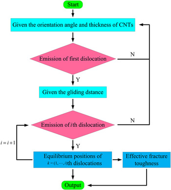
IC will be performed to characterize the shielding influence of dislocations on crack growth. To assist the computation of equilibrium positions of emitted dislocations and effective fracture toughness of aligned CNTs-reinforced MMCs, a flow chart is given in Fig. 3.
Flow chart for the computation of equilibrium positions of emitted dislocations and effective fracture toughness of aligned CNTs-reinforced MMCs.

III. RESULTS AND DISCUSSION
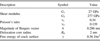
Before the calculation procedures are performed, some material constants must be defined first. Aligned multi-walled CNTs-reinforced nanocrystalline aluminum matrix composites are evaluated as an illustrative example, and the parameters used in the calculations are given in Table I.
Reference Hasson and Goux54,Reference Shen and Li55
For the sake of simplicity, the crack blunting is neglected. That is, the stress intensity factor
 $K_{\rm{I}}^{\rm{\sigma }}$
does not change during the process of emitting dislocations from a crack tip. In addition, as all know that in nanocrystalline materials with grain size d < 20 nm, several special deformation mechanisms, such as GB sliding
Reference Bobylev, Mukherjee, Ovid'ko and Sheinerman17
and rotational deformation,
Reference Liu, Zhou, Shen and Hui56
should be taken into consideration. However, detailed discussion of these deformation behaviors is beyond the scope of this paper, and attention here is mainly paid on aligned CNTs-reinforced nanocrystalline MMCs with matrix grain size d ≥ 20 nm. In this condition, emission of dislocations from the interfaces between aligned CNTs and metal matrix is expected to be the dominant mechanism to accommodate the propagation of a crack in MMCs.
Material properties used in the calculations for nanocrystalline Al Reference Hasson and Goux54 and multi-walled CNTs. Reference Shen and Li55

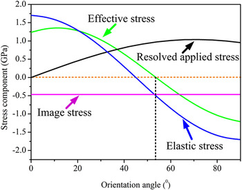
To discuss the influence of aligned CNTs on fracture toughness of nanocrystalline MMCs in detail, the conditions for the emission of first dislocation should be considered first. Figure 4 reveals the dependence of the four stress components for emission of first dislocation on the orientation angle of the aligned reinforcement. The wall thickness of aligned CNTs is set as t = 20.06 nm. The effective stress first increases slightly, and then decreases with the angle increases, as clearly demonstrated in this figure. It is of vital importance to note that when the angle θ ≈ 54°, the effective stress is equal to zero. Therefore, for the case with θ < 54°, emission of first dislocation is energetically favorable. In addition, compared with resolved applied stress, both effective stress and elastic stress are more sensitive to the variation of the angle, while the angle has no influence on the image stress. Effective stress depends significantly on the elastic stress, which is related with the existence of the reinforcement. Thus we can come to a preliminary conclusion that aligned CNTs have an important impact on the emission of dislocations from a crack tip under the given conditions.
The variations of the four stresses exerting on the first dislocation with the angles between aligned CNTs and the positive direction of x-axis.

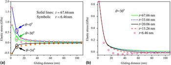
Then we change wall thickness of aligned CNTs instead of orientation angle to address the influence of wall thickness. Combining Eq. (4) with Eq. (5), we can obtain that the elastic stress relates with the wall thickness of aligned CNTs. Figure 5 elaborates the elastic stress as functions of gliding distance of the first dislocation for different wall thicknesses and orientation angles. It can be found from Fig. 5(a) that the discrepancies between elastic stresses of two kinds of wall thicknesses (t = 67.66 and 6.46 nm) are slight. The effect of wall thickness is not as obvious as the influence of orientation angle of the aligned reinforcement. In addition, elastic stresses of three different orientation angles tend toward stability with increasing the gliding distance. One feature shared by them is that the smaller gliding distance generates the larger effect induced by the aligned CNTs. To highlight the role of wall thickness, more evaluations have been performed and presented in Fig. 5(b). In this figure, the angle of aligned reinforcement is adopted as θ = 30° and five kinds of wall thicknesses have been considered. Generally speaking, when the first dislocation is near the crack tip, the thicker the wall thickness of aligned CNTs, the larger the elastic stress acting on the dislocation can be derived. However, smaller wall thickness (t = 6.46 nm) creates higher variation of the stress when the dislocation glides far away. What's more, the discrepancies of the stresses between different cases also disappear gradually with increases the distance of the dislocation to the crack tip. This means that the role of wall thickness of aligned CNTs becomes weaken with larger r 1. We can divide the Eq. (4) into two terms. The first term characterizes the shear stress in the sliding plane of edge dislocations situated on the boundary between two phases with different elastic moduli, while the second one considers the screening effect of the elastic field of dislocations by inner surface of aligned reinforcement. Compared with the variation of thickness, elastic stress has an even more pronounced change with the increase of distance. It is demonstrated that the first term has a more obvious effect on the generation and mobility of GB dislocations. In addition, the role of elastic stress in the gliding process of a dislocation gradually becomes weaken.
The effects of wall thickness of aligned CNTs on the elastic stress acting on the first dislocation. Comparison of (a) elastic stress with two kinds of wall thicknesses at three different orientation angles; (b) elastic stress with five kinds of wall thicknesses when the orientation angle is fixed as θ = 30°.

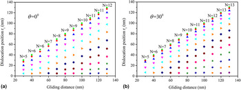
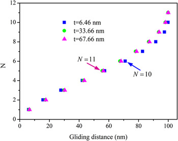
With the aid of Eqs. (1)–(8), we now evaluate maximum numbers of GB dislocations that can be emitted from the crack tip and define their equilibrium positions in a given gliding distance respectively. For definiteness, we put the wall thickness t = 33.66 nm and the angle of aligned reinforcement as θ = 30°. The relations between calculated results and gliding distance for orientation angles of 0° and 30° are depicted in Fig. 6, respectively. It is clear from the two cases that dislocations emitted from the crack tip are quite few when the distance is less than 100 nm. In other words, longer gliding distance for the emitted dislocations results in higher maximum number. Compared with maximum numbers obtained in the case with orientation angle θ = 0° in Fig. 6(a), larger numbers can be observed in Fig. 6(b).
Maximum numbers and equilibrium positions of edge dislocations emitted from a crack tip for different gliding distances for (a) θ = 0°, and (b) θ = 30°.

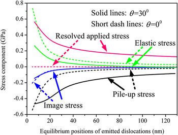
Based on the aforementioned calculations, the relations of the four stress components with equilibrium positions of emitted dislocations for the orientation angles of θ = 0° and θ = 30° are plotted in Fig. 7. When θ = 30°, the effects of resolved applied stress and pile-up stress are significant, while elastic stress plays most important role for the angle of θ = 0°.
Comparison of the four stress components as a function of equilibrium positions of emitted dislocations for θ = 0° and θ = 30°.

To further address the effect of aligned CNTs on the mobility and stability of the dislocations, their equilibrium numbers and the corresponding positions for different CNTs wall thicknesses are evaluated and shown in Fig. 8. In this figure, the largest gliding distance l = 100 nm is chosen as an illustrative example. In addition, we adopt the orientation angle θ = 30° in Fig. 8. It is found that the effect of the wall thickness on the numbers and positions of dislocations can be treated to be ignored. The results agree with the conclusion obtained from Fig. 5 that aligned CNTs inner surface has not-so-obvious influence on the elastic field of the emitted dislocations.
The maximum numbers and the corresponding positions of dislocations on a slip plane for different aligned CNTs wall thicknesses.

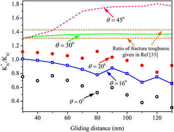
In this section, let us consider the dependence of fracture toughness of the composites on gliding distance of emitted dislocations. The ratios of
 ${{K_{{\rm{IC}}}^*} \mathord{\left/{\vphantom {{K_{{\rm{IC}}}^*} {{K_{{\rm{IC}}}}}}} \right\kern-\nulldelimiterspace} {{K_{{\rm{IC}}}}}}$
for the cases with five kinds of orientation angles (θ = 0°, 16°, 20°, 30°, and 45°) and the wall thickness t = 33.66 nm of the aligned reinforcement are clearly elaborated in Fig. 9. In addition, the comparisons between the calculated results with the experimental data
Reference Choi and Bae33
are also presented. Two different trends can be observed. When the orientation angles are set as 0°, 16°, and 20°, the ratios of fracture toughness decrease with increasing the gliding distance. However, it is obvious that the ratios in the cases with orientation angles of 30° and 45° larger than 1 and significantly increase in accordance with increasing gliding distance. It may be because of the fact that as the distance increases, the previous GB dislocations play a less pronounced role in hindering the emission of the subsequent dislocations until the maximum number becomes large enough. Therefore, the curves begin to flatten when the gliding distance reaches 100 nm and the ratio of fracture toughnesses with orientation angles of 30° and 45° are 1.37 and 1.77, respectively. Then the further improvement of the fracture toughness can be neglected even when the gliding distance continues to increase. This phenomenon is same to the results obtained by the bridge-toughening mechanism given by the analysis.
Reference Chen, Liu, He, Huang and Hwang40
As a corollary, above a critical length L
c = 100 nm and larger orientation angles of CNTs, the presence of the aligned reinforcement in nanocrystalline MMCs may provide a longer gliding distance for emitted dislocations, and the nanocomposites can achieve significant enhancement of fracture toughness.
The variations of the ratio of fracture toughness as a function of largest gliding distance for five kinds of orientation angles, and in comparison with experimental data. Reference Choi and Bae33

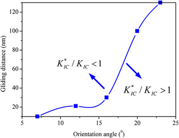
To further discuss the influence of aligned CNTs on the facture toughness of MMCs, Fig. 10 shows the distribution of ratio of fracture toughness of CNTs-reinforced MMCs in a certain range. For the composites with
 ${{{K_{{\rm{IC}}}^*} \mathord{\left/{\vphantom {{K_{{\rm{IC}}}^*} K}} \right\kern-\nulldelimiterspace} K}_{{\rm{IC}}}} > 1$
, the propagation of a crack will be retarded and the aligned reinforcement will bear the load and finally be pulled out. Otherwise, when the ratio of fracture toughness
 ${{{K_{{\rm{IC}}}^*} \mathord{\left/{\vphantom {{K_{{\rm{IC}}}^*} K}} \right\kern-\nulldelimiterspace} K}_{{\rm{IC}}}} \lt 1$
, the crack will easy to propagate along the interfaces between metal matrix and aligned reinforcement. Then sliding fracture mode is the most significant. Therefore, a conclusion can be achieved that the effect of aligned CNTs on the fracture toughness of nanocrystalline MMCs relates with orientation angle of the reinforcement and gliding distance of emitted dislocations.
The distribution of ratio of fracture toughness of CNTs-reinforced MMCs in a certain range.

IV. CONCLUSIONS
The propagation of a crack in nanocrystalline materials is a well documented phenomenon. However, comprehensive theoretical models discussing the role of aligned CNTs in this process for nanocrystalline MMCs are not available yet. Here, a dislocation model is suggested to characterize the interaction between the aligned reinforcement and GB dislocations emitted from a crack tip. In this model, the roles of the orientation and wall thickness of aligned CNTs, as well as the length of interface between the aligned reinforcement and metal matrix have been highlighted. It is found that the presence of the aligned reinforcement has an important influence on the critical shear stress for the emission of the first dislocation. The relations of equilibrium positions and maximum numbers of GB dislocations with aligned CNTs/matrix interface lengths for different orientations and wall thicknesses are evaluated respectively. Compared with the wall thickness, the orientation angle of the aligned reinforcement plays a more significant role in the mobility and stability of the dislocations emitted from the crack tip. In addition, the dependence of the enhanced fracture toughness on the aligned CNTs/matrix interface length is also calculated. The results show that the existence of aligned CNTs results in an increase of critical crack intensity factor by 77% than that in the dislocation free case under the conditions that the orientation angle is θ = 45° and the wall thickness is set as t = 33.66 nm. What's more, further improvement of the fracture toughness can be neglected above a critical length of CNTs L c = 100 nm, even when the interface length continues to increase. The result is in good agreement with the conclusion obtained by the bridge-toughening mechanism for CNTs-reinforced hard/soft matrix composites. Reference Chen, Liu, Huang and Hwang39,Reference Chen, Liu, He, Huang and Hwang40
ACKNOWLEDGMENTS
This work was supported by Key Project of Chinese Ministry of Education (211061), National Natural Science Foundation of China (10502025, 10872087, 11272143), Program for Chinese New Century Excellent Talents in university (NCET-12-0712), Ph.D. Programs Foundation of Ministry of Education of China (20133221110008).