INTRODUTION
Intense electron-beam accelerator (IEBA) based on Tesla transformer has been researched widely (Katsuki et al., Reference Katsuki, Takano, Namihira and Akiyama2001; Liu et al., Reference Liu, Yin, Ge, Zhan, Cheng, Feng, Shu, Zhang and Wang2007a, Reference Liu, Zhan and Zhang2007b, Reference Liu, Zhan, Zeng, Feng, Yin, Zhang and Wang2007c, Reference Liu, Cheng, Qian, Ge, Zhang and Wang2009; Cheng et al., Reference Cheng, Liu, Qian and Zhang2009a, Reference Cheng, Liu, Qian, Zhang and Zhang2009b; Peng et al., Reference Peng, Liu, Song and Su.2010) in the field of pulsed power. Tesla transformer, which can be either air core (Cheng et al., Reference Cheng, Liu, Qian and Zhang2009a, Reference Cheng, Liu, Qian, Zhang and Zhang2009b; Lim & Cho, Reference Lim and Cho2010) or magnetic core (Bykov, Reference Bykov1992; Katsuki et al., Reference Katsuki, Takano, Namihira and Akiyama2001; Korovin et al., Reference Korovin, Gubanov, Gunin, Pegel and Stepchenko2001), was proposed by Nikola Tesla. Air core transformer has its advantages of small size and weight, low cost, and non-saturation features. But high coupling coefficient and long lifetime, which are important parameters of pulse transformer, are difficult to obtain (Ko & Nam, Reference Ko and Nam2004, Reference Ko and Nam2005). However, magnetic core transformer, which is widely used in the field of high power pulse power, has high coupling coefficient and high energy conversion efficiency (Mesyats et al., Reference Mesyats, Korovin, Gunin, Gubanov, Stepchenko, Grishin, Landl and Alekseenko2003; Su et al., Reference Su, Zhang, Liu, Song, Pan, Wang, Peng and Ding2009). IEBA based on Tesla transformer has been used in many fields, such as high power microwave driven (Miller et al., Reference Miller, Poukey and Wright1975; Weber et al., Reference Weber, Boller, Cooperstein, Kellogg, Stephanakis and Swanekamp1993; Tarasenko et al., Reference Tarasenko, Shunailov, Shpak and Kostyrya2005), X-ray radiography (Weber et al., Reference Weber, Allen, Commisso, Cooperstein, Hinshelwood, Mosher, Murphy, Ottinger, Phipps, Schumer, Stephanakis, Swanekamp, Threadgold, Biddle, Clough, Jones, Sinclair, Swatton, Carden and Oliver2008), and radiation effects testing (Weber et al., Reference Weber, Hinshelwood, Murphy, Stephanakis and Harper-Slaboszewicz2004) and so on.
In this paper, an IEBA based on magnetic core Tesla transformer (MCTT) and Blumlein pulse forming line (PFL) of water dielectric is constructed and described. The output voltage of transformer is about 740 kV when charging voltage is 40 kV in experiments. Two typical structures of Blumlein PFL were studied. In the first one, the electric field intensity between internal cylinder and middle cylinder is equal to that between middle cylinder and outer cylinder. In the second one, the resistance of inner line is equal to that of outer line. The waveform of output voltage at the load is impacted by the sizes of internal cylinder, middle cylinder, and outer cylinder. Experiments results show that the output voltage of diode is about 596 kV, electron beam current is about 60 kA, and the pulse duration is about 100 ns when charging voltage is 40 kV. It was suitable and will be used to drive MILO and modify the surface properties of materials. This accelerator works stably and reliably in our laboratory.
DESIGN OF MAGNETIC CORE TESLA TRANSFORMER
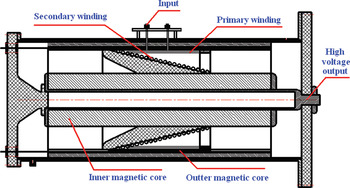
A magnetic core Tesla transformer was designed, constructed, and employed to charge the water Blumlein PFL. The structure of magnetic core Tesla transformer is shown in Figure 1, it is mainly consist of primary winding, secondary winding, inner magnetic core, outer magnetic core, input port, high voltage output port, outer cylinder, and internal support cylinder. Both inner and outer magnetic cores were made of silicon steel sheets. The radius and length of inner magnetic core are 4 cm and 110 cm, respectively. Outer magnetic core, which length is 110 cm and radius is 28.5 cm, is attached onto the outer cylinder. The transformer has a primary winding of 2-turns surrounding a 39-turns secondary winding, the length of both primary and secondary windings are 50 cm. Primary winding was made of copper strip with 50 cm width. And secondary winding, which is a taper winding, surrounds inner magnetic core. The inductance of primary windings L P, the inductance of secondary windings L S and the coupling coefficient k are 9.284 µH, 3.481 µH, and 0.920, respectively.
Configuration of the MCTT.

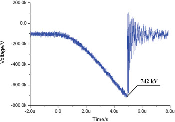
Figure 2 shows the output voltage waveform of MCTT. The output voltage of MCTT rises up to 742 kV when the primary winding circuit is charged at 40 kV, and the rise time is about 5 µs (Fig. 2).
Output voltage waveform of MCTT when charging voltage is 40 kV.

DESIGN OF BLUMLEIN PULSE FORMING LINE
Two typical structures of Blumlein PFL were constructed. In the first one, the electric field intensity between internal cylinder and middle cylinder is equal to that between middle cylinder and outer cylinder. In the second one, the resistance of inner line is equal to that of outer line. The waveform of output voltage at load is impacted by the sizes of internal cylinder, middle cylinder and outer cylinder.
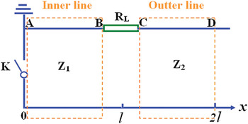
Equivalent circuit of the PFL discharge into the load of IEBA.

Theoretical Calculation
The Blumlein PFL consists of three coaxial cylindrical lines filled with de-ionized water as dielectric. The PFL formed by the inner conductor and the middle conductor is usually called the inner line. If the PFL is formed by the middle conductor and the outer conductor, it is called the outer line. The wave impedance of the inner line and outer line are Z 1 and Z 2, respectively. So during the Blumlein line discharge into the load, the equivalent circuit of the Blumlein line is shown in Figure 3, where K is the main switch, A B is the inner line, C D is the outer line, and R L is the load. The voltage at point C in Figure 3 is just the output voltage at the load. In order to get the output voltage at the load, the voltage at point C needs to be solved, so a coordinate system is built in Figure 3; the main switch is the zero point. When PFL is charged to a voltage V B (V B < 0), once the main switch K is closed, the PFL cannot stay in equilibrium since the PFL elementary capacitors adjacent to the load R L start discharging. So the voltages at the inner line and outer line satisfied the equations

In the above equations, L 1, C 1, u 1(x, t), i 1(x, t), and L 2, C 2, u 2(x, t), i 2(x, t) are inductances per unit, capacitances per unit, and voltages and currents of the inner line and outer line, respectively. When t = 0, the initial conditions of Eq. (1) are
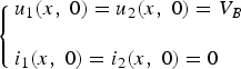
and for the characteristic of the PFL, the boundary conditions are
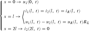
Then Laplace transform is used to solve Eq. (1). So the voltage at the load is

where p is the parameter in Laplace transform and  is the transmission time of electromagnetic wave which transmits from x = 0 to x = l. For α and k in Eq. (4), they are

Discussion with Different Conditions

For this condition, the resistance of inner line is equal to that of outer line, and the load resistance is matched completely with the PFL, and α = 0, k = 0, then putting α = 0, k = 0 into Eq. (1) leads to

where l(t) is the step function, and it is defined as
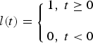
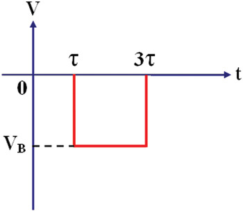
So, once the main switch is closed, the output voltage at the load can be seen in Figure 4. It shows that the output voltage at the load turns to be zero.
Numerical calculation results of output voltage at the load (R L) of IEBA when Z 1 = Z 2, Z L = Z 1 + Z 2.

Z1 ≠ Z2 , RL = Z1 + Z2
In this case, the electric field intensity between internal cylinder and middle cylinder is equal to that between middle cylinder and outer cylinder, and α ≠ 0, k = 0 then putting α ≠ 0, k = 0 into Eq. (1) leads to

where l(t) is the step function.
Figure 5a shows that k = 0, α > 0, the output waveform at the load is a damped oscillation wave. And when k = 0, α< 0, the output waveform at the load is a damped bipolar oscillation wave (Fig. 5b).
Numerical calculation results of output voltage at the load (RL) of IEBA when Z 1 ≠ Z 2, Z L = Z 1 + Z 2, (a) α > 0; (b) α < 0.

PSPICE SIMULATION ANALYSES
Model of the Simulation
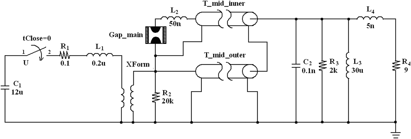
In order to verify the correctness of the theory above, Pspics circuit analysis was used to simulate the accelerator based on magnetic core Tesla transformer and Blumlein PFL. Figure 6 shows schematically the circuit model. The whole circuit is connected to components built in Pspice component storage or modeled by the authors according to the performance of the device. Parameters of all components in the circuit are valued according to the practical circuit or theoretical calculation. As shown in Figure 6, C 1 is the primary energy-storage capacitance, and R 1 and L 1 are the resistance and inductance of primary winding circuit, MCTT and the main switch are modeled and indicated by XForm and Gap_main in the circuit, respectively. L 2 is the inductance of the main switch; T_mid_inner and T_mid_outer are connected in parallel to simulate the PFL, respectively. L 3 is the inductor that connects the inner conductor of the PFL to the ground. R 4 is the load of the IEBA. In the circuit, the operation voltage of the IEBA is controlled by the main switch Gap_main.
Pspice circuit schematic used to model the IEBA.

Simulation Results
Z 1 = Z 2 , R L = Z 1 + Z 2
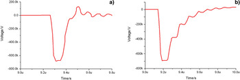
During the theoretical analysis, supposing L 2 = 50n, Z 1 = Z 2 = 4.5 Ω, R L = 9 Ω and τ = 60 ns. The output voltages of at the load can be obtained. Figures 7a and 7b show the simulation results. In Figure 7a, it clearly shows that once the main switch of the IEBA is closed, the output voltage at the load turns to be zero, and there is no oscillation wave at the output wave. This is accordant with the result of Figure 5a.
Simulation results of output voltage at the load (RL) of IEBA, (a) Z 1 = Z 2 = 4.5Ω, R L = 9Ω; (b) Z 1 = 7Ω, Z2 = 2Ω, R L= 9Ω.

Z 1 ≠ Z 2, R L = Z 1 + Z 2
Now, it is supposed that Z 1 = 7 Ω, Z 2 = 2 Ω, R L = 9 Ω and, τ = 60 ns. Figure 7b shows the simulation results. The output waveform at the load is a damped oscillation wave, and the cycle of damped oscillation wave is 2τ. This proves that the theoretical analysis in Figure 5b is right.
EXPERIMENTAL RESULT AND DISCUSSION
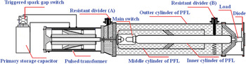
A couple of contrast experiments are used to verify the theoretical and Pspice simulation results. The structure of the IEBA is shown in Figure 8. It consists of the primary storage capacitor, triggered spark-gap switch (Cheng et al., Reference Cheng, Liu, Qian, Bai, Chen and Feng2010; Zhang et al., Reference Zhang, Liu, Cheng, Zhang, Qian, Bai, Feng and Liang2010) the magnetic core Tesla transformer, the water Blumlein line, main switch, and the field-emission diode (load) (Liu et al., Reference Liu, Yin, Ge, Zhan, Cheng, Feng, Shu, Zhang and Wang2007a, Reference Liu, Zhan and Zhang2007b, Reference Liu, Zhan, Zeng, Feng, Yin, Zhang and Wang2007c). The water with a resistivity of more than 10 MΩcm is used as the dielectric of the Blumlein PFL. For the capacitor of about 12 µF, 40 kV is used to provide primary pulse energy for the system of IEBA. The MCTT is installed between the spark-gap switch with a trigger electrode and the water Blumlein PFL. When the capacitor is charged to achieve the required voltage, the spark-gap switch is closed by a supply trigger pulse voltage. The capacitor discharges to provide about 60 kA for the primary winding of the pulse transformer.
Diagram of the IEBA based on MCTT and Blumlein PFL.

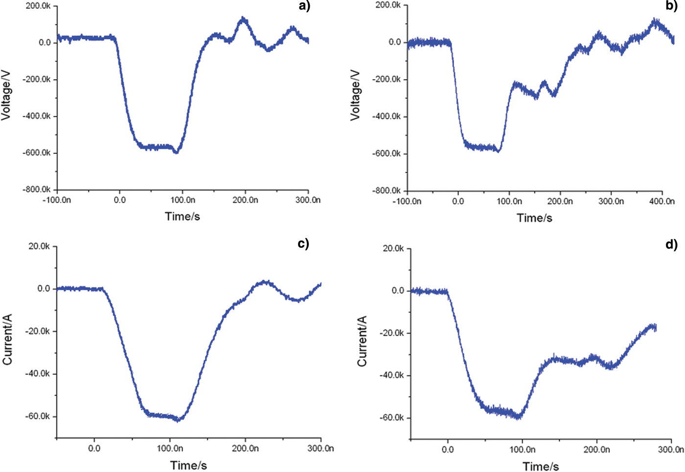
The Blumlein PFL consists of three coaxial cylindrical conductors with different diameters and a main switch. The metal components, which interface with water, are made of stainless steel. In the first structure, where Z 1 = Z 2 = 4.5 Ω, R L = Z 1 + Z 2 = 9 Ω, diameters of the outer, intermediate, and inner conductors are 82, 42, and 20 cm, respectively. And in the second structure, where Z 1 = 7 Ω, Z 2 = 2 Ω, R L = Z 1 + Z 2 = 9 Ω, diameters of the outer, intermediate, and inner conductors are 82, 59, and 20 cm, respectively. The transformer system was operated in an off-resonance single swing changing mode. The output voltage and output current waveform of the IEBA at the load was measured with the aid of water resistive divider (B). As shown in Figure 9, the output voltage and current at the load rise up to 600 kV and 60 kA, respectively, when the primary winding circuit was charged at 40 kV, the duration is about 100 ns, and the power is 36 GW, In the first structure, the output voltage and output current at the load turns to be zero. In the secondary structure, the output waveform at the load is a damped oscillation wave, and the cycle of damped oscillation wave is about 100 ns. These results verify the theoretical and Pspice simulation results.
Experimental results of output voltages and currents at the load (RL) of the IEBA, (a) Output voltage at the load when Z 1 = Z 2 = 4.5Ω, R L = 9Ω; (b) Output voltage at the load when Z 1 = 7Ω, Z 2 = 2Ω, R L = 9Ω; (c) Output current at the load when Z 1 = Z 2 = 4.5Ω, R L = 9Ω; (d) Output current at the load when Z 1 = 7Ω, Z 2 = 2Ω, R L = 9Ω.

APPLICATION OF FUTURE
Drive Magnetically Insulated Line Oscillator
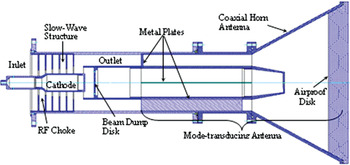
The MILO is a compact lightweight gigawatt-class coaxial crossed field microwave device. A MILO constructed by our laboratory was suitable to be driven by this IEBA with Z 1 = Z 2 = 4.5 Ω, R L = 9 Ω (Fan et al., Reference Fan, Zhong, Li, Shu, Zhang, Liu, Yang, Zhang, Yuan and Luo2008). The structure of MILO is shown in Figure 10 (Fan et al., Reference Fan, Yuan, Zhong, Shu and Luo2007a, Reference Fan, Yuan, Zhong, Shu, Zhang, Yang, Yang, Wang and Luo2007b). It consists of four-cavity SWS, which is preceded by a one-cavity radio frequency (RF) choke section. The load region is comprised of both the right end and the end surfaces of the cathode, a beam dump disk, and the inner conductor of the output coaxial transmission line (CTL). The electron beam emission region is confined by placing chosen velvet on the cathode running from the upstream side of the second choke vane to the right end of the cathode and the end surface of the cathode. The chosen velvet is pasted on the cathode with glue.
Configuration of the improved MILO.

In simulation, high-power microwave of transmission electron microscopy (TEM) mode is generated with peak power of 4.2 GW, frequency of 1.76 GHz, and peak power conversion efficiency of 12% when the voltage is 600 kV and the current is 52 kA (Fan et al., Reference Fan, Yuan, Zhong, Shu and Luo2007a, Reference Fan, Yuan, Zhong, Shu, Zhang, Yang, Yang, Wang and Luo2007b).
Materials Surface Modification
Electron beams is wildly used in the field of surface modification of metallic materials. Irradiation induces dynamic temperature fields in the surface layers giving rise to superfast heating, melting and evaporation, followed by superfast solidification of the material. The dynamic stress fields formed cause intense deformation processes in the material. As a result, metastable structure-phase states may appear in the surface layers, which are capable of providing improved physical, chemical and strength properties of the material unattainable with conventional surface treatment techniques.
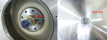
Figure 11 shows the cathode and the material that built in the diode of IEBA. The diameter of the cathode and the distance between cathode and metallic materials can be changed conveniently. So the metallic materials can be bombarded by electron beams with different density. The whole equipment of metallic materials modification has been structured, the further studies are in progress.
Structure of the cathode and the material that built in the diode of IEBA.

CONCLUSION
An intense electron-beam accelerator based on a magnetic core Tesla transformer is constructed and described. And two different structures Blumlein PFL are constructed. The output voltage of transformer is 742 kV, diode voltage is about 596 kV, electron beam current is about 60 kA, and the pulse duration is about 100 ns when the charging voltage is 40 kV. The MILO driven and Materials surface modification were the two main applications in the future. And now this accelerator works stably.