1 Introduction
This work studies the dynamic response of a liquid-filled tube due to the forced axial motion of an internal rigid cylinder. This configuration is relevant to various minimally invasive medical procedures in which slender devices are inserted into fluid-filled biological vessels. For example, recent technologies for Percutaneous coronary intervention involve insertion of cylindrical devices into blocked blood vessels (Rogers & Laird Reference Rogers and Laird2007; Davis Reference Davis2015). Similar methods are used in the field of interventional radiology, such as laser angioplasty (Serruys, Foley & De Feyter Reference Serruys, Foley and De Feyter1993), microvascular plug deployment (Pellerin et al. Reference Pellerin, Maleux, Déan, Pernot, Golzarian and Sapoval2014) and removing blood clots by thrombolysis and thrombectomy (Dunn & Weisse Reference Dunn and Weisse2015). Additional relevant procedures are endoscopies of body organs which contain liquid, e.g. cystoscopy (Chew et al. Reference Chew, Buffington, Kendall, Osborn and Woodsworth1996), as well as the frequently used procedure of urinary catheterization (Nacey & Delahijnt Reference Nacey and Delahijnt1993).
The examined configuration is actuated by an external force which induces a viscous flow field, applying fluidic stress on the fluid–solid interface and creating deformation of the tube, thus modifying the flow field. This interaction between viscous and elastic effects is relevant to various research fields (Duprat & Stone Reference Duprat and Stone2015), including locomotion at low Reynolds numbers (Wiggins & Goldstein Reference Wiggins and Goldstein1998; Camalet & Jülicher Reference Camalet and Jülicher2000), flow in flexible and collapsible tubes (Heil Reference Heil1996, Reference Heil1998; Marzo, Luo & Bertram Reference Marzo, Luo and Bertram2005) and the dynamics of membrane-bound particles (Vlahovska et al. Reference Vlahovska, Young, Danker and Misbah2011; Abreu et al. Reference Abreu, Levant, Steinberg and Seifert2014) among many others (Lister, Peng & Neufeld Reference Lister, Peng and Neufeld2013; Hewitt, Balmforth & De Bruyn Reference Hewitt, Balmforth and De Bruyn2015; Elbaz & Gat Reference Elbaz and Gat2016).
Fluid–solid interactions, in geometries similar to the one investigated here, have been extensively studied in the context of medical operations and biological flows. For example, previous works analysing the fluid mechanics of catheterized arteries include Karahalios (Reference Karahalios1990), who investigated flow in an axisymmetric cross-section of a catheterized artery, and estimated the shear stress at the artery wall due to catheterization. Sarkar & Jayaraman (Reference Sarkar and Jayaraman2001) modelled the pulsating blood flow in the annular cross-section between a catheter and an elastic tube and calculated the induced pressure gradient along the elastic tube. Vajravelu et al. (Reference Vajravelu, Sreenadh, Devaki and Prasad2011) modelled a non-Newtonian Herschel–Bulkley fluid flow in an elastic tube, representing a catheterized artery. Kumar et al. (Reference Kumar, Chandel, Kumar and Kumar2013) showed that the effective viscosity, flow rate and arterial wall shear stress are significantly altered in the catheterized site.
Other relevant works studied the motion of closely fitting solids in elastic tubes filled with viscous fluid, as a model of blood cells in narrow capillaries. Such problems involve the effects of the hydrodynamic stress generated in the lubricating film between the two bodies and the elastic stress which develops as a result of the contact of the particle and the tube. This type of analysis was first done by Lighthill (Reference Lighthill1968) who provided analytical solutions for the pressure field in such configurations, as well as predicting a necking phenomena next to the contact point. Later, Tözeren, Özkaya & Tözeren (Reference Tözeren, Özkaya and Tözeren1982) found the force required to maintain the motion of the particle, in addition to calculation of the fluid pressure field and the elastic deformation. Tani et al. (Reference Tani, Cambau, Bico and Reyssat2017) examined the friction force between the inner solid and the elastic tube in the case of a dry sphere–tube contact and in the case of lubrication by a thin fluid layer. Another recent relevant work is Park et al. (Reference Park, Tixier, Christensen, Arnbjerg-Nielsen, Zwieniecki and Jensen2018), who presented both analysis and experimental data of viscous flow in a bio-inspired soft valve configuration. In this context, the authors studied a cylinder and a concentric sphere with a narrow gap between them, and obtained the effect of the sphere on the nonlinear relation between the externally applied pressure difference and the flow rate.
The aim of this work is to analyse the motion of a solid cylinder within a liquid-filled tube, due to a prescribed external force, in relevance to various medical procedures. In § 2 we begin by defining the geometrical and physical properties of the examined configuration, as well as stating the governing lubrication equation and integral constraints of the system. Analysis of the simpler case of small linearized elastic deformations is presented in § 3. We then present the large deformation nonlinear dynamics for insertion (§ 4) and extraction (§ 5) of the cylinder from the elastic tube. In § 6 we provide concluding remarks.
2 Problem formulation and governing equations
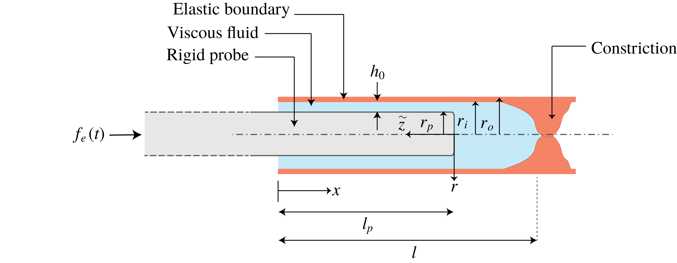
We study a Newtonian, incompressible, creeping flow due to the motion of a rigid cylinder within a liquid-filled elastic tube, as shown in figure 1. The inner cylinder represents a simplified model of a minimally invasive medical device and the linearly elastic tube is a simplified model of a bounding biological vessel (artery, urethra, etc.). An external force is applied on the cylinder, which consequently moves in relation to the tube.
Illustration of the examined configuration (at rest) and definition of the coordinate system. A rigid tube is located within a semi-closed liquid-filled elastic tube. The cylinder can be extracted from, or inserted into, the tube by an external axial force;
 $h_{0}$
is the initial gap between the cylinder and the tube,
 $l_{p}$
is the length of the inserted tube,
 $r_{p}$
is the radius of the tube,
 $l$
is the length from the inlet to the constriction closing the tube,
 $r_{i}$
and
 $r_{o}$
are the inner and outer radii of the tube, respectively.

Assuming axisymmetry, we denote a cylindrical coordinate system
 $(x,r)$
with origins at the centre of the opening of the tube. We denote time
 $t$
, liquid velocity
 $(u,v)$
, liquid gauge pressure
 $p$
, liquid viscosity
 $\unicode[STIX]{x1D707}$
, liquid density
 $\unicode[STIX]{x1D70C}$
and volume flux
 $v_{q}(t)$
entering or existing the tube through the inlet. We denote the length of the cylinder which penetrated into the tube
 $l_{p}$
, Young’s modulus of the tube
 $E$
, tube radial deformation
 $d_{r}$
, tube inner radius
 $r_{i}$
and outer radius
 $r_{o}$
, tube length
 $l$
, tube wall thickness
 $w=r_{o}-r_{i}$
, inner cylinder radius at rest
 $r_{p}$
. The gap between the cylinder and the tube at rest is
 $h_{0}=r_{i}-r_{p}$
:
 $f_{e}(t)$
denotes external force applied on the cylinder;
 $\tilde{z}$
is an auxiliary moving coordinate located at the tip of the penetrating cylinder, and is related to the
 $x$
coordinate by
 $\tilde{z}=l_{p}(t)-x$
.
Hereafter, normalized variables are denoted by uppercase letters and characteristic parameters are denoted by lowercase letters with asterisks (e.g. if
 $f$
is a dimensional variable,
 $f^{\ast }$
is the characteristic value of
 $f$
and
 $F=f/f^{\ast }$
is the corresponding normalized variable).
We define the normalized coordinates
 $X,R$
(starting at the tube inlet), the normalized moving coordinate
 $\tilde{Z}$
(starting at the penetrated side of the cylinder), and time
 $T$
 $$\begin{eqnarray}X=\frac{x}{l},\quad R=\frac{r}{r_{i}},\quad \tilde{Z}=\frac{\tilde{z}}{l_{p}}=\frac{l_{p}-x}{l_{p}},\quad T=\frac{t}{t^{\ast }}.\end{eqnarray}$$
The normalized radial deformation
 $D_{r}$
, pressure
 $P$
, external force
 $F_{e}$
and penetrated length
 $L_{p}$
are
 $$\begin{eqnarray}D_{r}=\frac{d_{r}}{d_{r}^{\ast }},\quad P=\frac{p}{p^{\ast }},\quad F_{e}=\frac{f_{e}}{f_{e}^{\ast }},\quad L_{p}=\frac{l_{p}}{l_{p}^{\ast }},\end{eqnarray}$$
where the relations between
 $d_{r}^{\ast }$
,
 $p^{\ast }$
,
 $l_{p}^{\ast }$
,
 $f_{e}^{\ast }$
and
 $t^{\ast }$
are derived for various limits in the following sections. The ratio of initial gap
 $h_{0}$
to characteristic radial deformations is denoted by
 $$\begin{eqnarray}\unicode[STIX]{x1D706}_{h}=\frac{h_{0}}{d_{r}^{\ast }}.\end{eqnarray}$$
Small ratios required in applying the lubrication approximation are
 $$\begin{eqnarray}\frac{h_{0}}{r_{i}}\ll 1,\quad \frac{d_{r}^{\ast }+h_{0}}{l_{p}^{\ast }}\ll 1,\quad \frac{d_{r}^{\ast }+h_{0}}{l_{p}^{\ast }}\frac{\unicode[STIX]{x1D70C}u^{\ast }(h_{0}+d_{r}^{\ast })}{\unicode[STIX]{x1D707}}\ll 1\end{eqnarray}$$
corresponding to a slender configuration in both axial and radial coordinates, along with negligible inertial effects. The elastic shell model requires the small ratios
 $$\begin{eqnarray}\frac{w}{r_{i}}\ll 1,\quad \frac{d_{r}^{\ast }}{r_{i}}\ll 1,\end{eqnarray}$$
corresponding to thin wall thickness and small elastic deformations.
The ratio between the penetrated length of the cylinder and the length of the tube is defined by
 $$\begin{eqnarray}\unicode[STIX]{x1D700}_{l}=\frac{l_{p}^{\ast }}{l}<1.\end{eqnarray}$$
For the majority of this work, we will use the leading-order relation between the pressure inside the tube and its radial deformation (Timoshenko & Woinowsky-Krieger Reference Timoshenko and Woinowsky-Krieger1959),
 $$\begin{eqnarray}P(X,T)=\frac{Ewd_{r}^{\ast }}{p^{\ast }r_{i}^{2}}D_{r}(X,T),\end{eqnarray}$$
and thus
 $p^{\ast }=d_{r}^{\ast }Ew/r_{i}^{2}$
, and
 $P=D_{r}$
for all cases hereafter. Relation (2.7) assumes linear elasticity, corresponding to small deformations and constant wall thickness (Timoshenko & Woinowsky-Krieger Reference Timoshenko and Woinowsky-Krieger1959), and does not include the effects of viscous shear which were shown to be negligible in the examined configuration (see Elbaz & Gat Reference Elbaz and Gat2016).
In order to obtain the governing equations, we apply the lubrication approximation for flow in the gap region between the cylinder and the tube. Normalizing the lubrication equations according to (2.1)–(2.2) and neglecting
 $O(h_{0}/r_{i})$
terms yields the relevant Reynolds equation (the derivation is given in appendix A)
 $$\begin{eqnarray}\displaystyle \frac{\unicode[STIX]{x2202}D_{r}}{\unicode[STIX]{x2202}T}-\frac{t^{\ast }Ewh_{0}^{3}}{r_{i}^{2}12\unicode[STIX]{x1D707}l^{2}}\frac{\unicode[STIX]{x2202}}{\unicode[STIX]{x2202}X}\left[\frac{\unicode[STIX]{x2202}P}{\unicode[STIX]{x2202}X}\left(1+\frac{D_{r}}{\unicode[STIX]{x1D706}_{h}}\right)^{3}\right]+\frac{\unicode[STIX]{x1D700}_{l}\unicode[STIX]{x1D706}_{h}}{2}\frac{\unicode[STIX]{x2202}}{\unicode[STIX]{x2202}X}\left[\frac{\unicode[STIX]{x2202}L_{p}}{\unicode[STIX]{x2202}T}\left(1+\frac{D_{r}}{\unicode[STIX]{x1D706}_{h}}\right)\right]=0. & & \displaystyle\end{eqnarray}$$
The Reynolds equation is supplemented by two integral constraints (see also appendix A for an abbreviated derivation of these equations). The first is integral mass conservation, given in scaled form by
 $$\begin{eqnarray}L_{p}-L_{p}(0)-\frac{2r_{i}d_{r}^{\ast }l}{r_{p}^{2}l_{p}^{\ast }}\int _{0}^{1}D_{r}\,\text{d}X+\frac{h_{0}^{3}p^{\ast }t^{\ast }}{6r_{p}\unicode[STIX]{x1D707}{l_{p}^{\ast }}^{2}}\left(\int _{0}^{T}\frac{1}{L_{p}}\frac{\unicode[STIX]{x2202}P}{\unicode[STIX]{x2202}\tilde{Z}}\bigg|_{\tilde{Z}=1}\,\text{d}\tilde{T}\right)=0,\end{eqnarray}$$
where gauge pressure at the inlet is zero,
 $P(X=0)=D_{r}(X=0)=0$
. The first term in (2.9) is the volume of liquid displaced by the advancing cylinder, the second term is the volume change due to solid deformation and the last term is the total volume of the liquid which exited the system through the annular inlet since
 $T=0$
.
The second constraint is a scaled integral momentum equation on the inner cylinder given by
 $$\begin{eqnarray}F_{e}-\frac{\unicode[STIX]{x03C0}r_{p}^{2}p^{\ast }}{f_{e}^{\ast }}P(\tilde{Z}=0)-\frac{2\unicode[STIX]{x03C0}r_{p}\unicode[STIX]{x1D707}{l_{p}^{\ast }}^{2}}{d_{r}^{\ast }f_{e}^{\ast }t^{\ast }}\left[L_{p}\frac{\unicode[STIX]{x2202}L_{p}}{\unicode[STIX]{x2202}T}\int _{0}^{1}\frac{\text{d}\tilde{Z}}{\unicode[STIX]{x1D706}_{h}+D_{r}}\right]=0,\end{eqnarray}$$
where the first term is the external force, the second term is the pressure at the base of the penetrating cylinder (
 $\tilde{Z}=0$
) and the third term is the shear stress on the cylinder wall (
 $R=R_{p}$
).
Since a general analytic solution of the above equations is not available, approximated solutions for various limits will be pursued in the following sections in order to provide insight regarding the examined configuration. We begin by examining the simplest linearized limit.
3 Linearized insertion and extraction dynamics,
 $|f_{e}|\ll Eh_{0}w$

In this section we begin studying this problem by examining the simplified linearized case of small deformations where
 $\unicode[STIX]{x1D706}_{h}\gg 1$
. For
 $\unicode[STIX]{x1D706}_{h}=h_{0}/d_{r}^{\ast }\gg 1$
and
 $h_{0}l/r_{i}l_{p}^{\ast }\lesssim 1$
, order of magnitude analysis of (2.9) yields
 $$\begin{eqnarray}t^{\ast }=\frac{6r_{p}\unicode[STIX]{x1D707}{l_{p}^{\ast }}^{2}}{h_{0}^{3}p^{\ast }},\end{eqnarray}$$
and substituting (3.1) into (2.10) yields
 $p^{\ast }=f_{e}^{\ast }/\unicode[STIX]{x03C0}r_{p}^{2}$
and
 $P(\tilde{Z}=0)=F_{e}+O(h_{0}^{2}/r_{p}^{2})$
.
In order to obtain approximated solution of (2.8), under the integral constraints (2.9) and (2.10), we introduce the regular asymptotic expansions
 $$\begin{eqnarray}P(\tilde{Z},T)=D_{r}(\tilde{Z},T)=D_{r,0}+\unicode[STIX]{x1D706}_{h}^{-1}D_{r,1}\end{eqnarray}$$
and
 $$\begin{eqnarray}L_{p}(T)=L_{p,0}+\unicode[STIX]{x1D706}_{h}^{-1}L_{p,1}.\end{eqnarray}$$
Substituting the expansions (3.2) and collecting terms for each order, the leading order of (2.8)–(2.10) is given by
 $$\begin{eqnarray}\frac{\unicode[STIX]{x2202}^{2}P_{0}}{\unicode[STIX]{x2202}\tilde{Z}^{2}}=0,\quad L_{p,0}-L_{p}(0)+\int _{0}^{T}\frac{1}{L_{p,0}}\frac{\unicode[STIX]{x2202}P_{0}}{\unicode[STIX]{x2202}\tilde{Z}}\bigg|_{\tilde{Z}=1}\,\text{d}\tilde{T}=0,\end{eqnarray}$$
along with the boundary conditions
 $P_{0}(\tilde{Z}=0,T)=F_{e}$
and
 $P_{0}(\tilde{Z}=1,T)=0$
. The leading-order equations are readily solved, yielding
 $$\begin{eqnarray}L_{p,0}(T)=\sqrt{2\int _{0}^{T}F_{e}(\tilde{T})\,\text{d}\tilde{T}+{L_{p}}^{2}(0)},\quad P_{0}(\tilde{Z},T)=(1-\tilde{Z})F_{e}.\end{eqnarray}$$
Substituting the expansions (3.2) and collecting terms of order
 $O({\unicode[STIX]{x1D706}_{h}}^{-1})$
of (2.8)–(2.10), yields the first-order equations
 $$\begin{eqnarray}\frac{\unicode[STIX]{x2202}^{2}P_{1}}{\unicode[STIX]{x2202}\tilde{Z}^{2}}=0,\quad L_{p,1}-\int _{0}^{1}D_{r,0}\,\text{d}X-\int _{0}^{T}\frac{\unicode[STIX]{x2202}P_{0}}{\unicode[STIX]{x2202}\tilde{Z}}\bigg|_{\tilde{Z}=1}\frac{L_{p,1}}{L_{p,0}^{2}}\,\text{d}\tilde{T}=0,\end{eqnarray}$$
along with the homogeneous boundary conditions
 $P_{1}(\tilde{Z}=0,T)=0$
and
 $P_{1}(\tilde{Z}=1,T)=0$
.
In order to solve (3.5), the integral of the leading-order deformation is split into two regions,
 $$\begin{eqnarray}\int _{0}^{1}D_{r}\,\text{d}X=\unicode[STIX]{x1D700}_{l}L_{p}\int _{0}^{1}D_{r}\,\text{d}\tilde{Z}+\int _{\unicode[STIX]{x1D700}_{l}L_{p}}^{1}D_{r}\,\text{d}X,\end{eqnarray}$$
where the first region represents the penetrated region (see region
 $\tilde{z}>0$
in figure 1) and the second region represents the unpenetrated region of the tube in which the pressure is approximately constant and equals
 $P_{0}(\tilde{Z}=0,T)=F_{e}$
. Substituting (2.7) into (3.6), yields
 $$\begin{eqnarray}\int _{0}^{1}D_{r,0}\,\text{d}X=\unicode[STIX]{x1D700}_{l}L_{p,0}\int _{0}^{1}(1-\tilde{Z})F_{e}\,\text{d}\tilde{Z}+F_{e}(1-\unicode[STIX]{x1D700}_{l}L_{p,0})=F_{e}\left(1-\frac{\unicode[STIX]{x1D700}_{l}}{2}L_{p,0}\right).\end{eqnarray}$$
Differentiating (3.5) with respect to
 $T$
after substituting the expression obtained in (3.7), as well as the solution of
 $P_{0}(\tilde{Z},T)$
from (3.4), yields the ordinary differential equation governing
 $L_{p,1}$
 $$\begin{eqnarray}\frac{\unicode[STIX]{x2202}L_{p,1}}{\unicode[STIX]{x2202}T}+\frac{F_{e}}{L_{p,0}^{2}}L_{p,1}=\frac{\unicode[STIX]{x2202}}{\unicode[STIX]{x2202}T}\left[F_{e}\left(1-\unicode[STIX]{x1D700}_{l}\frac{L_{p,0}}{2}\right)\right]\end{eqnarray}$$
and thus the first-order correction, which accounts for effects of elasticity, is
 $$\begin{eqnarray}L_{p,1}=e^{-\int _{0}^{T}(F_{e}/L_{p,0}^{2})\,\text{d}\unicode[STIX]{x1D70F}}\int _{0}^{T}\frac{\unicode[STIX]{x2202}}{\unicode[STIX]{x2202}T}\left[F_{e}\left(1-\unicode[STIX]{x1D700}_{l}\frac{L_{p,0}}{2}\right)\right]e^{\int _{0}^{\tilde{T}}(F_{e}/L_{p,0}^{2})\,\text{d}\unicode[STIX]{x1D70F}}\,\text{d}\tilde{T},\quad P_{1}(\tilde{Z},T)=0.\end{eqnarray}$$
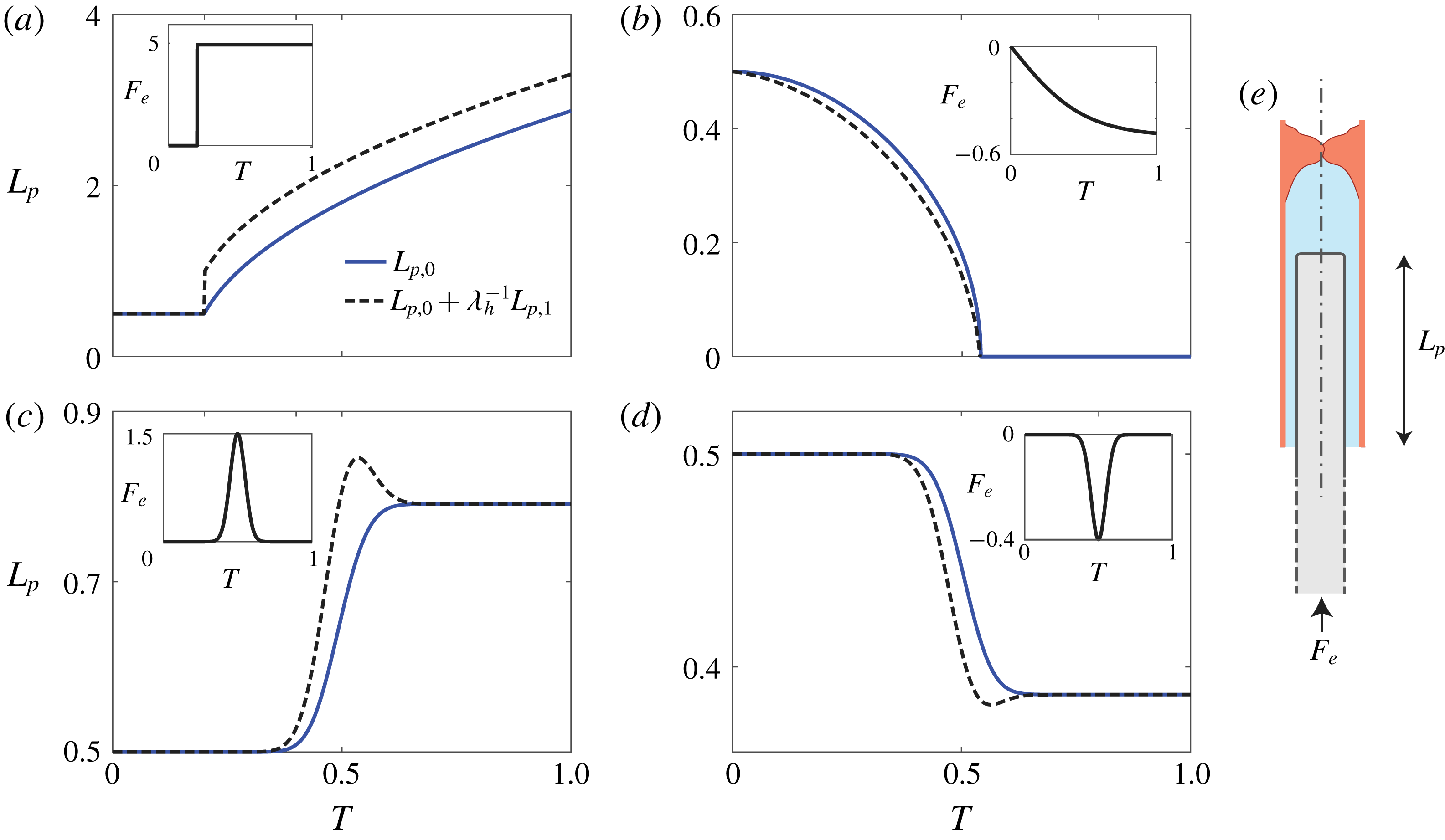
We illustrate these results in figure 2, showing the motion of the cylinder for various external force profiles. The leading-order solutions
 $L_{p,0}$
given by (3.4) represent reference rigid configurations and are marked by solid lines. The effect of elasticity is presented by the difference between the leading- and first-order solutions,
 $L_{p,0}+\unicode[STIX]{x1D706}_{h}^{-1}L_{p,1}$
given by (3.9a,b
) and marked by dashed lines. The actuating external force versus time profiles are presented as insets within the panels. For all panels, the normalized initial insertion of the cylinder is
 $L_{p}(T=0)=0.5$
, the ratio of cylinder to tube length is
 $\unicode[STIX]{x1D700}_{l}=l_{p}^{\ast }/l=0.1$
, the initial gap to tube radius ratio is
 $h_{0}/r_{p}=0.1$
and the initial gap to radial displacement ratio is
 $\unicode[STIX]{x1D706}_{h}=h_{0}/d_{r}^{\ast }=10$
.
Motion due to various external force profiles. Smooth lines denote (rigid) leading-order solution (3.4) and dashed lines denote first-order solutions which include effects of elasticity (3.9a,b
). In all panels
 $L_{p}(T=0)=0.5$
,
 $\unicode[STIX]{x1D700}_{l}=0.1$
,
 $h_{0}/r_{p}=0.1$
and
 $\unicode[STIX]{x1D706}_{h}=10$
. The examined force profiles (see insets) are
 $F_{e}(T)=5\cdot H(T-0.2)$
(a),
 $-0.5\cdot \tanh (2T)$
(b),
 $1.5\cdot \exp [(-T-0.5)^{2}/2\cdot 0.05^{2}]$
(c),
 $-0.4\cdot \exp [(-T-0.5)^{2}/2\cdot 0.05^{2}]$
(d). The leading-order motion is always is the direction of the external force. However, elastic effects yield extrema points for non-monotonic forces (c,d), along with a motion of the cylinder in the direction opposite to the external force.

Panels (a) and (b) present the motion of the inner cylinder due to a sudden positive forcing (
 $F_{e}=5H(T-0.2)$
) and gradual negative forcing (
 $F_{e}=-0.5\tanh (2T)$
). For positive forcing, as expected, elasticity increases the penetration of the cylinder into the tube. While the positive pressure reduces viscous resistance via increased gap thickness, the dominant effect is related to deformation created ahead of the inner cylinder, which allows penetration of the cylinder due to displacement of liquid via the increased cross-sectional areas. This is evident also in panel (b), where elasticity decreases
 $L_{p}$
, even though negative pressure increases viscous resistance in this case. Panels (c) and (d) present forcing patterns of respectively positive and negative Gaussian profiles with a mean of 0.5 and variance of
 $0.05^{2}$
. In this case, tube elasticity creates a maximum point, and thus changes the direction of motion of the inner cylinder as the elastic energy stored in the tube is gradually released.
The linearized limit used in this section allowed a short preliminary examination of the system dynamics for a simplified case, showing the effect of elasticity on viscous resistance, as well as the effect of potential elastic energy. We proceed to examine nonlinear configurations in the following sections.
4 Nonlinear insertion dynamics,
$f_{e}\gg Eh_{0}w$

This section examines a sufficiently large positive external force which inserts the cylinder into the tube and creates large deformations compared with the initial gap between the inner cylinder and the external tube (i.e.
 $\unicode[STIX]{x1D706}_{h}=h_{0}/d_{r}^{\ast }\ll 1$
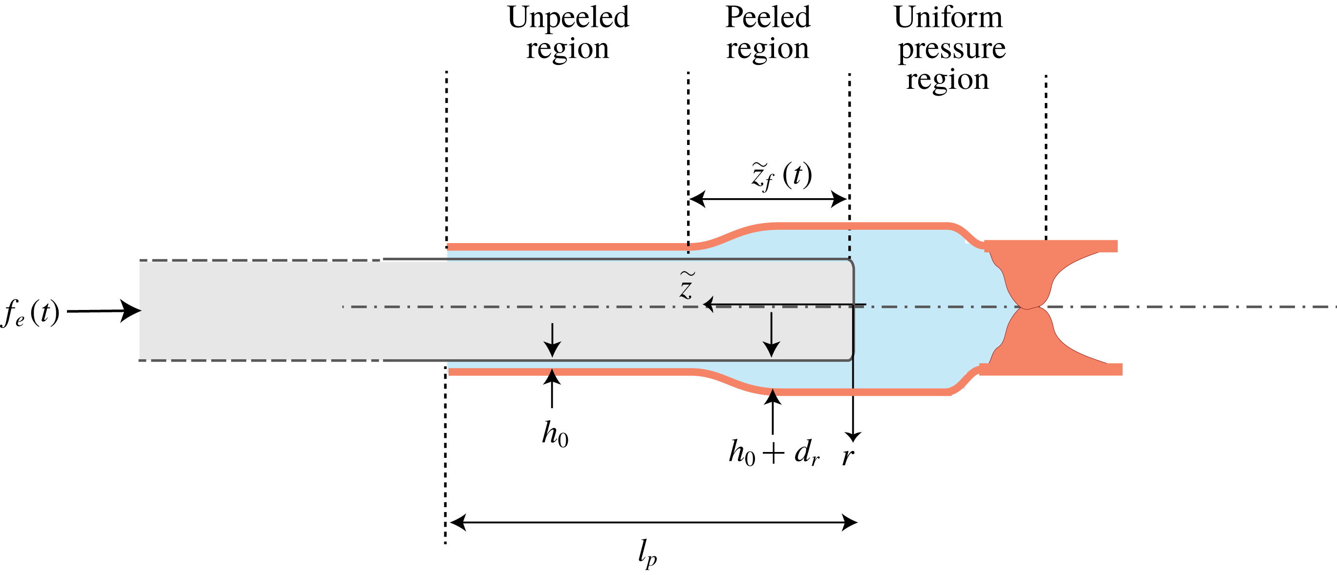
). In this limit, as shown below, the Reynolds evolution equation (2.8) is reduced to a porous medium equation, a nonlinear diffusion equation characterized by solutions with distinct propagation fronts. The non-smooth front separates a pressurized region with significant deformation of the tube and a region of zero gauge pressure (trivial solution) and zero deformation of the tube where the front has not propagated yet. We refer the reader to Vázquez (Reference Vázquez2007) for a detailed discussion of such equations. This section will focus on the dynamics involving such a front, and thus an additional geometric division is required, separating the region before the front and after the front. This division is presented in figure 3.
The location of the front is denoted hereafter as
 $\tilde{z}_{F}$
, and in normalized form by
 $$\begin{eqnarray}\tilde{Z}_{F}=\frac{\tilde{z}_{F}}{l_{p}}.\end{eqnarray}$$
The three different domains are presented in figure 3 and include: (I) the unpeeled region
 $\tilde{z}_{F}(t)<\tilde{z}\leqslant l_{p}(t)$
which the deformation front has not yet reached, (II) The peeled lubrication region
 $0<\tilde{z}\leqslant \tilde{z}_{F}(t)$
and (III)
 $l_{p}(t)<x\leqslant l$
, the uniformly pressurized bulk of the tube.
Illustration of the configuration for an external insertion force, in the limit of large deformation. We distinguish between three domains: the unpeeled region, the peeled region and the uniformly pressurized region. These domains change in time due to the advance of the cylinder,
 $l_{p}(t)$
, and the propagation of the peeling front,
 $\tilde{z}_{F}(t)$
.

4.1 Scaling and derivation of governing equations
The above physical limit allows us to simplify the governing Reynolds’ equation, as well as the integral mass and momentum conservation constraints (2.9)–(2.10).
The compact support of the fluidic front (see discussion below (4.13)) allows us to simplify the integral mass conservation to
 $$\begin{eqnarray}L_{p}-L_{p}(0)=\frac{2r_{i}d_{r}^{\ast }l}{r_{p}^{2}l_{p}^{\ast }}\left[(1-\unicode[STIX]{x1D700}_{l}L_{p})P(\tilde{Z}=0)+\unicode[STIX]{x1D700}_{l}L_{p}\int _{0}^{\tilde{Z}_{F}}D_{r}\,\text{d}\tilde{Z}\right].\end{eqnarray}$$
For the integral force conservation equation, the effect of shear at the peeled region II can be neglected compared with the unpeeled region I, thus simplifying (2.10) to
 $$\begin{eqnarray}F_{e}-\frac{\unicode[STIX]{x03C0}{r_{p}}^{2}p^{\ast }}{f_{e}^{\ast }}P(\tilde{Z}=0)-\frac{2\unicode[STIX]{x03C0}r_{p}\unicode[STIX]{x1D707}{l_{p}^{\ast }}^{2}}{f_{e}^{\ast }h_{0}t^{\ast }}\left[L_{p}\frac{\unicode[STIX]{x2202}L_{p}}{\unicode[STIX]{x2202}T}(1-\tilde{Z}_{F})\right]=0.\end{eqnarray}$$
Together with (2.7) and
 $p^{\ast }=f_{e}^{\ast }/\unicode[STIX]{x03C0}r_{p}^{2}$
we can simplify (4.2) to
 $$\begin{eqnarray}P(\tilde{Z}=0)=\frac{Ewl_{p}^{\ast }}{2lp^{\ast }r_{p}}\left[\frac{L_{p}-L_{p}(0)}{1-\unicode[STIX]{x1D700}_{l}L_{p}}\right]-\unicode[STIX]{x1D700}_{l}\left[\frac{\displaystyle L_{p}\int _{0}^{\tilde{Z}_{F}}D_{r}\,\text{d}\tilde{Z}}{1-\unicode[STIX]{x1D700}_{l}L_{p}}\right],\end{eqnarray}$$
and scaling of (4.4) therefore yields
 $l_{p}^{\ast }=p^{\ast }2lr_{p}/Ew$
. Substituting (4.4) into (4.3), the set of equations governing the large deformation limit are
 $$\begin{eqnarray}F_{e}=\left[\frac{\displaystyle L_{p}\left(1-\unicode[STIX]{x1D700}_{l}\int _{0}^{\tilde{Z}_{F}(T)}D_{r}\,\text{d}\tilde{Z}\right)-L_{p}(0)}{1-\unicode[STIX]{x1D700}_{l}L_{p}}\right]+\unicode[STIX]{x1D6F1}_{1}\left[L_{p}\frac{\unicode[STIX]{x2202}L_{p}}{\unicode[STIX]{x2202}T}(1-\tilde{Z}_{F}(T))\right],\end{eqnarray}$$
and
 $$\begin{eqnarray}\frac{\unicode[STIX]{x2202}D_{r}}{\unicode[STIX]{x2202}T}=\unicode[STIX]{x1D6F1}_{2}\frac{\unicode[STIX]{x2202}}{\unicode[STIX]{x2202}\tilde{Z}}\left(\frac{1}{L_{p}^{2}}\frac{\unicode[STIX]{x2202}P}{\unicode[STIX]{x2202}\tilde{Z}}D_{r}^{3}\right)-\frac{(1-2\tilde{Z})}{2L_{p}}\frac{\unicode[STIX]{x2202}L_{p}}{\unicode[STIX]{x2202}T}\frac{\unicode[STIX]{x2202}D_{r}}{\unicode[STIX]{x2202}\tilde{Z}},\end{eqnarray}$$
where, by using the obtained relations between the characteristic values (
 $f_{e}^{\ast }=p^{\ast }\unicode[STIX]{x03C0}r_{p}^{2}$
,
 $l_{p}^{\ast }=p^{\ast }2lr_{p}/Ew$
and
 $d_{r}^{\ast }=p^{\ast }r_{i}^{2}/Ew$
)
 $\unicode[STIX]{x1D6F1}_{1}$
and
 $\unicode[STIX]{x1D6F1}_{2}$
can be presented in terms of
 $f_{e}^{\ast }$
,
 $t^{\ast }$
and known geometric and physical parameters of the problem,
 $$\begin{eqnarray}\unicode[STIX]{x1D6F1}_{1}=\frac{8l^{2}\unicode[STIX]{x1D707}f_{e}^{\ast }}{\unicode[STIX]{x03C0}r_{p}h_{0}(Ew)^{2}t^{\ast }},\quad \unicode[STIX]{x1D6F1}_{2}=\frac{t^{\ast }f_{e}^{\ast }r_{i}^{4}}{\unicode[STIX]{x03C0}48\unicode[STIX]{x1D707}l^{2}r_{p}^{4}}.\end{eqnarray}$$
For a prescribed
 $f_{e}^{\ast }$
, two different time scales are evident in (4.5). The first is
 $$\begin{eqnarray}t_{shear}^{\ast }=\frac{8l^{2}\unicode[STIX]{x1D707}f_{e}^{\ast }}{\unicode[STIX]{x03C0}r_{p}h_{0}(Ew)^{2}},\end{eqnarray}$$
which is the time scale in which shear is a leading-order term in (4.5a
), (shear is described by the second right-hand side term). For
 $t^{\ast }\ll t_{shear}^{\ast }$
, pressure effects can be neglected in (4.5a
) and the dominant balance would be between the external force and viscous shear.
The second time scale is
 $$\begin{eqnarray}t_{peeling}^{\ast }=\frac{\unicode[STIX]{x03C0}48\,\unicode[STIX]{x1D707}l^{2}r_{p}^{4}}{f_{e}^{\ast }r_{i}^{4}},\end{eqnarray}$$
and represents the time scale in which pressure-driven flow is a dominant term in region II (see first right-hand side term in (4.5b )).
4.2 Matched asymptotics
The value of
 $\unicode[STIX]{x1D6F1}_{1}$
decreases with
 $t^{\ast }$
while
 $\unicode[STIX]{x1D6F1}_{2}$
increases with
 $t^{\ast }$
, thus indicating that the early-time dynamics is governed by shear, while the late-time dynamics is governed by pressurization of the liquid within the tube. Hereafter, in order to proceed, we limit our focus to configurations with the small ratios of
 $$\begin{eqnarray}\unicode[STIX]{x1D700}_{t}=\frac{t_{shear}^{\ast }}{t_{peeling}^{\ast }}\ll 1,\quad \unicode[STIX]{x1D700}_{l}=\frac{l_{p}^{\ast }}{l}\ll 1.\end{eqnarray}$$
Additionally, this section examines the response of the configuration to a specific case of suddenly applied external force of the form
 $$\begin{eqnarray}F_{e}=H(T),\end{eqnarray}$$
where
 $H(T)$
is the Heaviside function.
4.2.1 Outer region
For time scales of
 $t^{\ast }=t_{peeling}^{\ast }$
, we obtain
 $\unicode[STIX]{x1D6F1}_{2}=1$
and
 $\unicode[STIX]{x1D6F1}_{1}=\unicode[STIX]{x1D700}_{t}$
and thus the leading order (4.5) is simplified to
 $$\begin{eqnarray}F_{e}=\left[\frac{\displaystyle L_{p}\left(1-\unicode[STIX]{x1D700}_{l}\int _{0}^{\tilde{Z}_{F}(T)}D_{r}\,\text{d}\tilde{Z}\right)-L_{p}(0)}{1-\unicode[STIX]{x1D700}_{l}L_{p}}\right]+O(\unicode[STIX]{x1D700}_{t}),\end{eqnarray}$$
and
 $$\begin{eqnarray}\frac{\unicode[STIX]{x2202}D_{r}}{\unicode[STIX]{x2202}T}=\frac{\unicode[STIX]{x2202}}{\unicode[STIX]{x2202}\tilde{Z}}\left(\frac{1}{L_{p}^{2}}\frac{\unicode[STIX]{x2202}P}{\unicode[STIX]{x2202}\tilde{Z}}D_{r}^{3}\right)-\frac{(1-2\tilde{Z})}{2L_{p}}\frac{\unicode[STIX]{x2202}L_{p}}{\unicode[STIX]{x2202}T}\frac{\unicode[STIX]{x2202}D_{r}}{\unicode[STIX]{x2202}\tilde{Z}}.\end{eqnarray}$$
Within the outer region, we apply regular asymptotics with regard to the second small parameter
 $\unicode[STIX]{x1D700}_{l}$
(which is
 $\gg \unicode[STIX]{x1D700}_{t}$
). The asymptotic expansions for both
 $L_{p}$
and
 $P=D_{r}$
are defined by
 $$\begin{eqnarray}L_{p}=L_{p,0}+\unicode[STIX]{x1D700}_{l}L_{p,1},\quad P=D_{r}=D_{r,0}+\unicode[STIX]{x1D700}_{l}D_{r,1}.\end{eqnarray}$$
Applying standard asymptotic procedure to (4.10a ) yields
 $$\begin{eqnarray}L_{p}=F_{e}+L_{p}(0)+\unicode[STIX]{x1D700}_{l}(F_{e}+L_{p}(0))\left(\int _{0}^{\tilde{Z}_{F}(T)}D_{r,0}\,\text{d}\tilde{Z}-F_{e}\right),\end{eqnarray}$$
which depends only on the leading-order deformation
 $D_{r,0}$
. Substituting
 $L_{p}$
from (4.12) into (4.10b
), yields the partial differential equation governing
 $D_{r,0}$
,
 $$\begin{eqnarray}\frac{\unicode[STIX]{x2202}D_{r,0}}{\unicode[STIX]{x2202}T}=\frac{1}{4(F_{e}+L_{p}(0))^{2}}\frac{\unicode[STIX]{x2202}^{2}}{\unicode[STIX]{x2202}\tilde{Z}^{2}}(D_{r,0}^{4}),\end{eqnarray}$$
which is a porous medium equation of order 4, supplemented by the initial condition of
 $D_{r,0}(\tilde{Z},0)=0$
and boundary condition of
 $P_{0}=D_{r,0}(0,T)=1$
(we set
 $F_{e}=H(T>0)=1$
).
Self-similar treatment of the above equation (4.13) is possible, following the approach presented by Zel’dovich & Kompaneets (Reference Zel’dovich and Kompaneets1950) and Barenblatt (Reference Barenblatt1952). Defining the self-similar variable
 $$\begin{eqnarray}\unicode[STIX]{x1D702}=2(F_{e}+L_{p}(0))\frac{\tilde{Z}}{T^{1/2}}\end{eqnarray}$$
yields an ordinary differential equation for
 $f(\unicode[STIX]{x1D702})=D_{r,0}$
 $$\begin{eqnarray}(f^{4}(\unicode[STIX]{x1D702}))^{\prime \prime }+{\textstyle \frac{1}{2}}\unicode[STIX]{x1D702}f^{\prime }(\unicode[STIX]{x1D702})=0,\end{eqnarray}$$
along with initial and boundary conditions
 $$\begin{eqnarray}\quad f(0)=1,\quad f(\unicode[STIX]{x1D702}_{f})=0.\end{eqnarray}$$
Equation (4.15) can be solved numerically (see Vázquez Reference Vázquez2007; Elbaz & Gat Reference Elbaz and Gat2016), yielding
 $$\begin{eqnarray}\unicode[STIX]{x1D702}_{f}=1.704,\quad \int _{0}^{\unicode[STIX]{x1D702}_{f}}f(\unicode[STIX]{x1D702})\,\text{d}\unicode[STIX]{x1D702}=1.305.\end{eqnarray}$$
Evaluating (4.14) at
 $\unicode[STIX]{x1D702}_{f}$
and substituting in the result from (4.16) gives
 $$\begin{eqnarray}\tilde{Z}_{F}=0.852\frac{T^{1/2}}{F_{e}+L_{p}(0)},\end{eqnarray}$$
as well as the mass flux entering region II
 $$\begin{eqnarray}\int _{0}^{\tilde{Z}_{F}}D_{r,0}\,\text{d}\tilde{Z}=\frac{\unicode[STIX]{x2202}\tilde{Z}}{\unicode[STIX]{x2202}\unicode[STIX]{x1D702}}\int _{0}^{\unicode[STIX]{x1D702}_{f}}f(\unicode[STIX]{x1D702})\,\text{d}\unicode[STIX]{x1D702}=0.652\frac{T^{1/2}}{F_{e}+L_{p}(0)}.\end{eqnarray}$$
Substituting (4.18) into (4.12), yields the solution for
 $L_{p}$
for the outer region
 $$\begin{eqnarray}L_{p}=F_{e}+L_{p}(0)+\unicode[STIX]{x1D700}_{l}[0.652(T^{1/2})-F_{e}(F_{e}+L_{p}(0))].\end{eqnarray}$$
The initial condition
 $L_{p}(0)$
of the outer region needs to be related, via matching, to the inner-region solution derived in the next subsection.
4.2.2 Inner region
We introduce the rescaled inner-region coordinate
 $$\begin{eqnarray}\bar{T}=\frac{T}{\unicode[STIX]{x1D700}_{t}}.\end{eqnarray}$$
For the inner region we observe the system from the shear time scale,
 $t^{\ast }\sim \unicode[STIX]{x1D700}_{t}t_{peeling}^{\ast }$
, when the peeling process has a negligible effect on the system. The peeling front remains immobile up to a
 $\unicode[STIX]{x1D700}_{t}$
correction, hence
 $\tilde{Z}_{F}(\unicode[STIX]{x1D700}_{t}\bar{T})\sim O(\unicode[STIX]{x1D700}_{t})$
. Thus, the leading-order
 $O(1)$
balance in (4.5a
) yields the inner-region solution
 $\bar{L}_{p}$
:
 $$\begin{eqnarray}\bar{L}_{p}\frac{\unicode[STIX]{x2202}\bar{L}_{p}}{\unicode[STIX]{x2202}\bar{T}}=-\bar{L}_{p}+\bar{L}_{p}(0)+F_{e},\end{eqnarray}$$
which is the Abel equation of the second kind (Zaitsev & Polyanin Reference Zaitsev and Polyanin2002), for which a closed-form solution for Heaviside function forcing,
 $F_{e}(T)=H(T)$
is available. The inner-region dynamics is thus given by
 $$\begin{eqnarray}\bar{L}_{p}(\bar{T})=(\bar{L}_{p}(0)+F_{e})\left(1+W\left[-\frac{1}{\bar{L}_{p}(0)+F_{e}}\exp \left(-1-\frac{\bar{T}+C}{\bar{L}_{p}(0)+F_{e}}\right)\right]\right),\end{eqnarray}$$
where
 $W(T)$
is the Lambert-
 $W$
function (Corles et al.
Reference Corless, Gonnet, Hare, Jeffrey and Knuth1996) which satisfies
 $W(x\exp x)=x$
. The initial condition
 $\bar{L}_{p}(\bar{T}=0)=\bar{L}_{p}(0)$
gives the constant
 $C$
:
 $$\begin{eqnarray}C=-(F_{e}+\bar{L}_{p}(0))\ln (F_{e})-\bar{L}_{p}(0).\end{eqnarray}$$
4.2.3 Uniform solution
Matching between the inner and outer regions is required in order to obtain a uniform asymptotic solution. This yields the requirement
 $$\begin{eqnarray}\lim _{\bar{T}\rightarrow \infty }\bar{L}_{p}=\lim _{T\rightarrow 0}L_{p}\end{eqnarray}$$
and thus
 $\bar{L}_{p}(0)+F_{e}=L_{p}(0)+F_{e}$
, and
 $\bar{L}_{p}(0)=L_{p}(0)$
. The composite expansion is therefore given by
 $\bar{L}_{p}(\bar{T})+L_{p}(T)-(L_{p}(0)+F_{e})$
, yielding
 $$\begin{eqnarray}\displaystyle L_{p,uniform} & = & \displaystyle (L_{p}(0)+F_{e})\left\{1+\unicode[STIX]{x1D700}_{l}\left[\frac{0.652(T^{1/2})}{F_{e}+L_{p}(0)}-F_{e}\right]\right.\nonumber\\ \displaystyle & & \displaystyle +\left.W\left[-\frac{1}{L_{p}(0)+F_{e}}\exp \left(-1-\frac{T/\unicode[STIX]{x1D700}_{t}+C}{L_{p}(0)+F_{e}}\right)\right]\right\},\end{eqnarray}$$
which is the uniform solution representing the response of the configuration to a sudden external load. The above solution incorporates the effect of a propagating front. However, the location of the front will reach the end of the tube for
 $T>[(F_{e}+L_{p}(0))/0.852]^{2}$
(see (4.17)). Before proceeding to discuss and present the uniform solution (5.37), we will approximate the dynamics of the post-peeling regime and connect it to the uniform solution presented above.
4.2.4 Post-peeling dynamics
After the peeling front reaches the outlet, the entire tube is peeled and the viscous resistance can be approximated by the quasi-steady deformation solution of the Reynolds equation (4.13)
 $$\begin{eqnarray}D_{r}\approx (1-\tilde{Z})^{1/4}P(0)\end{eqnarray}$$
for
 $t^{\ast }\sim t_{peeling}^{\ast }$
, integral force balance yields
 $P(0)=F_{e}$
and integral conservation of mass yields
 $$\begin{eqnarray}\frac{\unicode[STIX]{x2202}L_{p}}{\unicode[STIX]{x2202}T}=\unicode[STIX]{x1D700}_{l}\frac{F_{e}^{4}}{L_{p}(T)},\end{eqnarray}$$
which is obtained by substituting (4.26) into the third left-hand side term of (2.9) and differentiating with respect to time. Integrating (4.27), we can obtain the post-peeling solution
 $$\begin{eqnarray}L_{p}=\sqrt{L_{p}^{2}(T=T_{B})+2\unicode[STIX]{x1D700}_{l}(T-T_{B})F_{e}^{4}}\end{eqnarray}$$
valid for
 $T>T_{B}=[(F_{e}+L_{p}(0))/0.852]^{2}$
.
4.3 Summary of nonlinear insertion dynamics
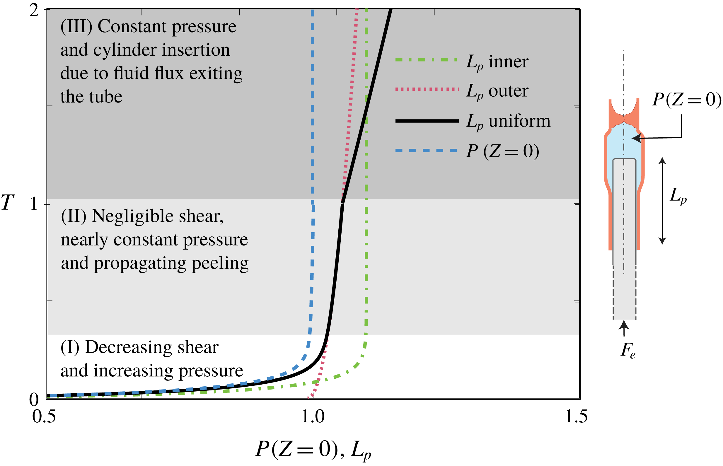
We illustrate these results in figure 4, which presents the location of the cylinder within the tube (
 $L_{p}$
) versus time, for the normalized parameters
 $F_{e}=H(T)$
,
 $\unicode[STIX]{x1D700}_{l}=0.1$
,
 $\unicode[STIX]{x1D700}_{t}=0.05$
and initial condition
 $L_{p}(0)=0.1$
. The figure presents the uniform solution (5.37) for
 $0<T<T_{B}$
and the post-peeling solution (4.28) for
 $T>T_{B}$
, where
 $T_{B}=[(F_{e}+L_{p}(0))/0.852]^{2}$
. The response of the examined configuration to a suddenly applied insertion force, at the large deformation limit (
 $\unicode[STIX]{x1D706}_{h}=d_{r}^{\ast }/h_{0}\gg 1$
), is shown to involve three distinct regimes. In the first regime (inner regime, § 4.2.2) the motion of the cylinder is governed by a balance between the shear stress, the fluidic pressure and the external force, while the effect of viscous peeling is negligible. As
 $t$
increases, the effect of shear decreases while the fluidic pressure increases. In the second regime (outer regime, § 4.2.1) the cylinder decelerates and the external force is balanced by fluidic pressure ahead of the cylinder, while effects of shear are negligible. The motion of the cylinder in this regime is governed by a balance between the fluidic volume which is displaced by insertion of the cylinder and the fluidic volume required to peel the inner cylinder from the external tube. Finally, as the peeling front reaches the inlet of the tube, a third post-peeling regime is obtained (§ 4.2.4). In this regime the cylinder motion is governed by a balance between the volume displaced by the cylinder and the fluidic flow outside of the configuration.
The next section we proceed to examine the opposite case of extraction of the cylinder from the tube.
The location of the cylinder within the tube
 $L_{p}$
, and liquid pressure ahead of the cylinder
 $P(Z=0)$
, versus time
 $T$
. The presented results are for the configuration defined by
 $L_{p}(T=0)=0.1$
,
 $\unicode[STIX]{x1D700}_{l}=0.1$
,
 $\unicode[STIX]{x1D700}_{t}=0.05$
and
 $F_{e}=H(T)$
. The white, light grey and dark grey parts denote the inner, outer and post-peeling regions, respectively.

5 Nonlinear extraction dynamics,
$f_{e}\lessapprox -Ewh_{0}$

This section will examine the forced extraction of an inner cylinder from a liquid-filled tube. In this case, a negative external force
 $f_{e}(t)<0$
creates a negative gauge pressure within the tube, and thus negative deformations. We will focus on the nonlinear limit involving negative deformations of the order of
 $h_{0}$
or greater (where
 $h_{0}$
is the initial gap between the cylinder and the tube).
The dynamics during extraction can be described by the previously derived results for insertion for the small deformation limit (
 $d_{r}^{\ast }/h_{0}\ll 1$
, see § 3), as well as for the initial shear-dominated inner-region large deformation limit (
 $d_{r}^{\ast }/h_{0}\gg 1$
,
 $t^{\ast }\sim 8l^{2}\unicode[STIX]{x1D707}f_{e}^{\ast }/\unicode[STIX]{x03C0}r_{p}h_{0}E^{2}w^{2}$
see § 4.2.2). However, outer-region solutions at the large deformation limit (
 $d_{r}^{\ast }/h_{0}\gg 1$
,
 $t^{\ast }\gg 8l^{2}\unicode[STIX]{x1D707}f_{e}^{\ast }/\unicode[STIX]{x03C0}r_{p}h_{0}E^{2}w^{2}$
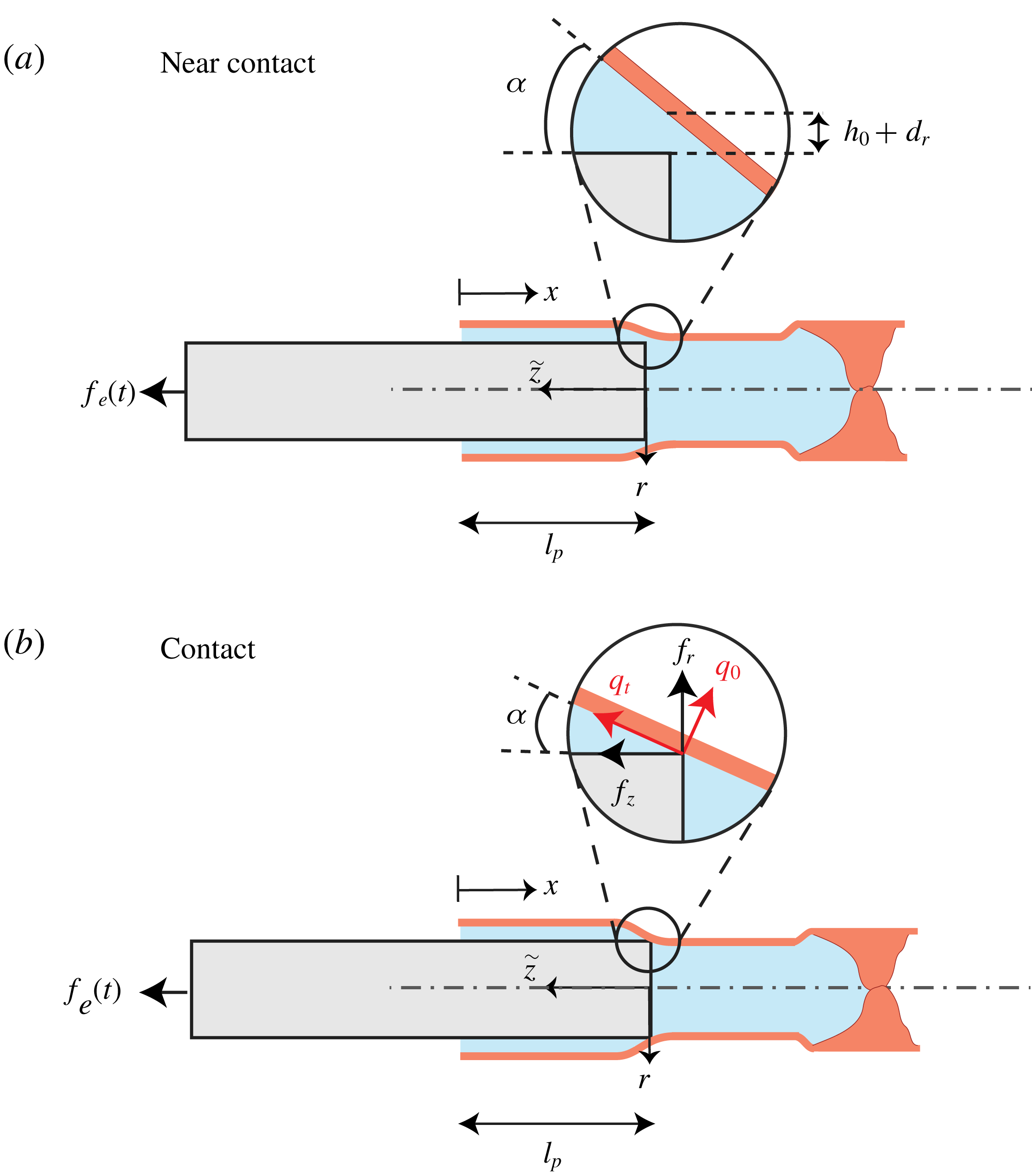
) exhibit essentially different dynamics. The negative gauge pressure created during extraction closes the gap between the cylinder and the tube, and may create contact between the two solids. This section will examine the case of nearly contacting cylinder and tube (see figure 5
a, § 5.1) and the case of contact (see figure 5
b, § 5.2).
Illustration of the configuration at extraction for (a) near-contact and (b) contact cases. Panel (a) presents the near-contact case, where the gap at
 $h_{0}+d_{r}(\tilde{z}=0)\rightarrow 0^{+}$
, thus nearly separating the liquid into two regions. The slope at
 $\tilde{z}=0$
is given by
 $\unicode[STIX]{x1D6FC}$
. Panel (b) presents contact, where the gap
 $h_{0}+d_{r}(\tilde{z}=0)=0$
, and additional friction forces
 $(f_{r},f_{z})$
act on the elastic tube. The forces (
 $q_{t},q_{0}$
) are projections of the friction into the directions normal and tangent to the surface of the elastic tube.

5.1 Near contact,
$f_{e}\rightarrow (-2\unicode[STIX]{x03C0}Ewh_{0}r_{p}^{2}/r_{i}^{2})^{+}$

For the limit of near contact between the tube and the cylinder (see figure 5
a) we define the normalized gap at
 $X=\unicode[STIX]{x1D700}_{l}L_{p}$
by
 $$\begin{eqnarray}D_{r}|_{X=\unicode[STIX]{x1D700}L_{p}}+1=\unicode[STIX]{x1D700}_{NC}H_{NC},\quad \unicode[STIX]{x1D700}_{NC}\ll 1,\end{eqnarray}$$
where
 $H_{NC}$
is the scaled minimal gap and the small parameter
 $\unicode[STIX]{x1D700}_{NC}$
will be later related to the extraction force (alternatively,
 $H_{NC}=(d_{r}|_{x=l_{p}}+h_{0})/(\unicode[STIX]{x1D700}_{NC}h_{0})\sim O(1)$
). This limit can be leveraged to the simplification of the governing equations, allowing analytical treatment. While the governing integral conservation equations of mass and momentum are largely unchanged, the equations governing the flow field and deformation are significantly modified.
5.1.1 Governing equations
The rapid change in fluid pressure near
 $X=\unicode[STIX]{x1D700}_{l}L_{p}$
for
 $\unicode[STIX]{x1D700}_{NC}\rightarrow 0$
requires us to include elastic bending effects in the
 $X$
direction. Following Timoshenko & Woinowsky-Krieger (Reference Timoshenko and Woinowsky-Krieger1959), the deformation of a circular cylindrical tube loaded axisymmetrically is described by
 $$\begin{eqnarray}K\frac{\unicode[STIX]{x2202}^{4}D_{r}(X,T)}{\unicode[STIX]{x2202}X^{4}}+D_{r}(X,T)\sim P(X,T),\end{eqnarray}$$
where
 $$\begin{eqnarray}K\equiv \frac{w^{2}r_{i}^{2}}{12l^{4}(1-\unicode[STIX]{x1D708}^{2})},\end{eqnarray}$$
the deformation
 $D$
is scaled by
 $d_{r}^{\ast }=h_{0}$
and the pressure
 $P$
is scaled by
 $p^{\ast }=Ewh_{0}/r_{i}^{2}$
. The external force
 $F_{e}$
is thus scaled by
 $f_{e}^{\ast }=\unicode[STIX]{x03C0}r_{p}^{2}p^{\ast }$
. Equation (5.2) replaces the previous relation (2.7) between fluid pressure and elastic deformation.
The limit of near contact is singular with regard to fluid resistance, and thus viscous resistance is defined by the small finite parameter
 $\unicode[STIX]{x1D700}_{NC}$
. Focusing on the region near
 $x=l_{p}$
, we apply a Taylor series around
 $X=\unicode[STIX]{x1D700}_{l}L_{p}$
and neglect higher-order terms. This allows us to simplify the pressure-flux relation to
 $$\begin{eqnarray}\displaystyle \dot{Q} & = & \displaystyle -\frac{\unicode[STIX]{x03C0}r_{i}p^{\ast }h_{0}^{3}}{3\unicode[STIX]{x1D707}\dot{q}^{\ast }l}\frac{\unicode[STIX]{x2202}P}{\unicode[STIX]{x2202}X}(D_{r}+1)^{3}\nonumber\\ \displaystyle & {\approx} & \displaystyle -\frac{\unicode[STIX]{x03C0}r_{i}p^{\ast }h_{0}^{3}}{3\unicode[STIX]{x1D707}\dot{q}^{\ast }l}\frac{\unicode[STIX]{x2202}P}{\unicode[STIX]{x2202}X}\left(D_{r}|_{X=\unicode[STIX]{x1D700}_{l}L_{p}}+1+\frac{\unicode[STIX]{x2202}D_{r}}{\unicode[STIX]{x2202}X}\bigg|_{X=\unicode[STIX]{x1D700}_{l}L_{p}}(X-\unicode[STIX]{x1D700}_{l}L_{p})\right)^{3},\end{eqnarray}$$
where
 $\dot{Q}$
is scaled by
 $\dot{q}^{\ast }=\unicode[STIX]{x03C0}r_{i}p^{\ast }h_{0}^{3}/3\unicode[STIX]{x1D707}l$
. Integrating from
 $X=\unicode[STIX]{x1D700}_{l}L_{p}$
to
 $X$
, and extracting the pressure difference in terms of flux
 $\dot{Q}$
, yields
 $$\begin{eqnarray}\displaystyle P|_{X=\unicode[STIX]{x1D700}_{l}L_{p}}-P|_{X} & = & \displaystyle (D_{r}|_{X=\unicode[STIX]{x1D700}_{l}L_{p}}+1)^{-2}\left(-2\frac{\unicode[STIX]{x2202}D_{r}}{\unicode[STIX]{x2202}X}\bigg|_{X=\unicode[STIX]{x1D700}_{l}L_{p}}\right)^{-1}\dot{Q}\nonumber\\ \displaystyle & & \displaystyle -\left(D_{r}|_{X=\unicode[STIX]{x1D700}_{l}L_{p}}+1+\frac{\unicode[STIX]{x2202}D_{r}}{\unicode[STIX]{x2202}X}\bigg|_{X=\unicode[STIX]{x1D700}_{l}L_{p}}(X-\unicode[STIX]{x1D700}_{l}L_{p})\right)^{-2}\left(-2\frac{\unicode[STIX]{x2202}D_{r}}{\unicode[STIX]{x2202}X}\bigg|_{X=\unicode[STIX]{x1D700}_{l}L_{p}}\right)^{-1}\dot{Q}.\nonumber\\ \displaystyle & & \displaystyle\end{eqnarray}$$
For
 $\unicode[STIX]{x1D700}_{NC}\rightarrow 0$
the pressure difference
 $P|_{X=\unicode[STIX]{x1D700}_{l}L_{p}}-P|_{X}$
asymptotes to a constant, defined only by the conditions near
 $X=\unicode[STIX]{x1D700}_{l}L_{p}$
. Applying
 $P(X=0)=0$
, and
 $D_{r}|_{X=\unicode[STIX]{x1D700}_{l}L_{p}}+1=H_{NC}\unicode[STIX]{x1D700}_{NC}\ll 1$
, we note that the first right-hand side term of (5.5) is
 $O(\unicode[STIX]{x1D700}_{NC}^{2})$
, while the second right-hand side term is
 $O(1)$
, thus the following relation is obtained:
 $$\begin{eqnarray}\dot{Q}\approx -2\unicode[STIX]{x1D700}_{NC}^{2}\left(\frac{\unicode[STIX]{x2202}D_{r}}{\unicode[STIX]{x2202}X}H_{NC}P\right)\bigg|_{X=\unicode[STIX]{x1D700}_{l}L_{p}},\end{eqnarray}$$
representing the flux only by the conditions at
 $X=\unicode[STIX]{x1D700}_{l}L_{p}$
(where
 $P(X=0)=0$
). Thus, the governing integral mass and momentum conservation equations for extraction are
 $$\begin{eqnarray}L_{p}-L_{p}(0)=\frac{2r_{i}h_{0}l}{r_{p}^{2}l_{p}^{\ast }}\int _{0}^{1}D_{r}\,\text{d}X-\frac{h_{0}^{4}Ewt^{\ast }\unicode[STIX]{x1D700}_{NC}^{2}}{3\unicode[STIX]{x1D707}l_{p}^{\ast }r_{p}^{2}lr_{i}}\int _{0}^{T}\left(\frac{\unicode[STIX]{x2202}D_{r}}{\unicode[STIX]{x2202}X}H_{NC}P\right)\bigg|_{X=\unicode[STIX]{x1D700}_{l}L_{p}}\text{d}\tilde{T}\end{eqnarray}$$
and
 $$\begin{eqnarray}F_{e}-P|_{X=\unicode[STIX]{x1D700}_{l}L_{p}}-\frac{2\unicode[STIX]{x1D707}{l_{p}^{\ast }}^{2}r_{i}^{2}}{r_{p}Ewh_{0}^{2}t^{\ast }}\left[L_{p}\frac{\unicode[STIX]{x2202}L_{p}}{\unicode[STIX]{x2202}T}\int _{0}^{1}\frac{\text{d}\tilde{Z}}{1+D_{r}}\right]=0.\end{eqnarray}$$
These equations are similar to § 4.1, with the exception of the last right-hand side term in (5.7), representing mass flux
 $\dot{Q}$
. Scaling of (5.7) and (5.8) yields
 $$\begin{eqnarray}l_{p}^{\ast }=\frac{2r_{i}h_{0}l}{r_{p}^{2}}\end{eqnarray}$$
and two dimensionless ratios
 $$\begin{eqnarray}\hat{\unicode[STIX]{x1D6F1}}_{1}=\frac{h_{0}^{3}Ew\unicode[STIX]{x1D700}_{NC}^{2}t^{\ast }}{6\unicode[STIX]{x1D707}l^{2}r_{i}^{2}},\quad \hat{\unicode[STIX]{x1D6F1}}_{2}=\frac{8\unicode[STIX]{x1D707}l^{2}r_{i}^{4}}{r_{p}^{5}Ewt^{\ast }}.\end{eqnarray}$$
Similarly to the case of nonlinear insertion dynamics, the ratio
 $\hat{\unicode[STIX]{x1D6F1}}_{1}$
decreases with
 $t^{\ast }$
while
 $\hat{\unicode[STIX]{x1D6F1}}_{1}$
increases with
 $t^{\ast }$
, suggesting different early-time and late-time dynamics. Thus two corresponding time scales are evident. The first is the time scale of the initial shear-dominated regime
 $$\begin{eqnarray}t_{shear}^{\ast }=\frac{8\unicode[STIX]{x1D707}l^{2}r_{i}^{4}}{r_{p}^{5}Ew}.\end{eqnarray}$$
The second time scale is of the late-time motion due to flow through near-contact gap between the cylinder and the tube,
 $$\begin{eqnarray}t_{NC}^{\ast }=\frac{6\unicode[STIX]{x1D707}l^{2}r_{i}^{2}}{Ewh_{0}^{3}\unicode[STIX]{x1D700}_{NC}^{2}}.\end{eqnarray}$$
For the examined configuration, the ratio between the two time scales is a geometrically small parameter, given by
 $$\begin{eqnarray}\unicode[STIX]{x1D700}_{t}=\frac{t_{shear}^{\ast }}{t_{NC}^{\ast }}=\frac{8h_{0}^{3}r_{i}^{2}\unicode[STIX]{x1D700}_{NC}^{2}}{6r_{p}^{5}}\ll 1\end{eqnarray}$$
and so
 $\unicode[STIX]{x1D700}_{t}\ll \unicode[STIX]{x1D700}_{NC}^{2}$
.
Substituting
 $t^{\ast }=t_{NC}^{\ast }$
, yields the governing equations
 $$\begin{eqnarray}L_{p}-L_{p}(0)=(1-\unicode[STIX]{x1D700}_{l}L_{p})P|_{X=\unicode[STIX]{x1D700}_{l}L_{p}}-\int _{0}^{T}\left(\frac{\unicode[STIX]{x2202}D_{r}}{\unicode[STIX]{x2202}X}H_{NC}P\right)\bigg|_{X=\unicode[STIX]{x1D700}_{l}L_{p}}\text{d}\tilde{T}\end{eqnarray}$$
and
 $$\begin{eqnarray}F_{e}-P|_{X=\unicode[STIX]{x1D700}_{l}L_{p}}-\unicode[STIX]{x1D700}_{t}\left(L_{p}\frac{\unicode[STIX]{x2202}L_{p}}{\unicode[STIX]{x2202}T}\int _{0}^{1}\frac{\text{d}\tilde{Z}}{1+D_{r}}\right)=0.\end{eqnarray}$$
We proceed by asymptotic expansions, based on perturbations from the exact contact state
 $\unicode[STIX]{x1D700}_{NC}=0$
(where
 $\unicode[STIX]{x1D700}_{NC}$
is defined from
 $D_{r}|_{X=\unicode[STIX]{x1D700}_{l}L_{p}}+1=H_{NC}\unicode[STIX]{x1D700}_{NC}\ll 1$
). We thus define the external extraction force by
 $$\begin{eqnarray}F_{e}=F_{e,0}(1-\unicode[STIX]{x1D700}_{NC}),\end{eqnarray}$$
where
 $F_{e,0}=F_{e,contact}$
is the external extraction force creating exact contact
 $D_{r}|_{X=\unicode[STIX]{x1D700}_{l}L_{p}}=-1$
, and thus zero flux
 $\dot{Q}=0$
. In addition, we define the expansion for the fluidic pressure
 $$\begin{eqnarray}P=P_{0}+\unicode[STIX]{x1D700}_{NC}P_{1}.\end{eqnarray}$$
We apply a matched asymptotic scheme, and begin by solving for the outer region
 $t\sim t_{NC}^{\ast }$
.
5.1.2 Outer region
The leading-order solution is the exact contact case, where
 $F_{e}=F_{e,contact}$
, and after the initial transition regime (§ 4.2.2), the contact point between the solids separates the fluid into two domains, and thus
 $\dot{Q}=0$
. The outer-region force balance (2.10) is simplified to
 $$\begin{eqnarray}P_{0}|_{X=\unicode[STIX]{x1D700}_{l}L_{p}}=F_{e,0},\quad P_{1}|_{X=\unicode[STIX]{x1D700}_{l}L_{p}}=-F_{e,0}\end{eqnarray}$$
and the pressure field is
 $$\begin{eqnarray}P_{0}(X,T)+\unicode[STIX]{x1D700}_{NC}P_{1}(X,T)=H(X-\unicode[STIX]{x1D700}L_{p})(F_{e,0}+\unicode[STIX]{x1D700}_{NC}F_{e,1}),\end{eqnarray}$$
where
 $H$
is the Heaviside function. The solid deformation is governed by (5.2), along with the boundary conditions,
 $\unicode[STIX]{x2202}^{2}D_{r}/\unicode[STIX]{x2202}X^{2}|_{X=0}=\unicode[STIX]{x2202}^{3}D_{r}/\unicode[STIX]{x2202}X^{3}|_{X=0}=D_{r}|_{X=1}=\unicode[STIX]{x2202}D_{r}/\unicode[STIX]{x2202}X|_{X=1}=0$
. Deformation patterns may be obtained numerically and analytically. However, since the singularity for
 $\unicode[STIX]{x1D700}_{NC}\rightarrow 0$
dictates that flux is governed by the conditions near
 $X=\unicode[STIX]{x1D700}_{l}L_{p}$
, only expressions for
 $D_{r}|_{X=\unicode[STIX]{x1D700}_{l}L_{p}}$
and
 $\unicode[STIX]{x2202}D_{r}/\unicode[STIX]{x2202}X|_{X=\unicode[STIX]{x1D700}_{l}L_{p}}$
are required. Due to linearity and symmetry considerations, the gap slope at
 $X=\unicode[STIX]{x1D700}_{l}L_{p}$
can be simplified to
 $$\begin{eqnarray}D_{r}|_{X=\unicode[STIX]{x1D700}_{l}L_{p}}={\textstyle \frac{1}{2}}(P|_{X<\unicode[STIX]{x1D700}_{l}L_{p}}+P|_{X>\unicode[STIX]{x1D700}_{l}L_{p}}),\end{eqnarray}$$
and
 $$\begin{eqnarray}\frac{\unicode[STIX]{x2202}D_{r}}{\unicode[STIX]{x2202}X}\bigg|_{X=\unicode[STIX]{x1D700}_{l}L_{p}}=\frac{(P|_{X>\unicode[STIX]{x1D700}_{l}L_{p}}-P|_{X<\unicode[STIX]{x1D700}_{l}L_{p}})}{(64K)^{1/4}}.\end{eqnarray}$$
Relation (5.20) is readily obtained from symmetry, since the value of the displacement in the symmetric transition between two constant forcing values must be the average of the displacements far from the transition. The slope is less evident, and the reader should consult Timoshenko & Woinowsky-Krieger (Reference Timoshenko and Woinowsky-Krieger1959).
Thus, the requirement of
 $D_{r,0}|_{X=\unicode[STIX]{x1D700}_{l}L_{p}}=-1$
yields
 $$\begin{eqnarray}F_{e,0}=P_{0}(\tilde{Z}=0)=-2\end{eqnarray}$$
and
 $H_{NC}$
is
 $$\begin{eqnarray}H_{NC}=1\end{eqnarray}$$
and
 $$\begin{eqnarray}\frac{\unicode[STIX]{x2202}D_{r,0}}{\unicode[STIX]{x2202}X}\bigg|_{X=\unicode[STIX]{x1D700}_{l}L_{p}}+\unicode[STIX]{x1D700}_{NC}\frac{\unicode[STIX]{x2202}D_{r,1}}{\unicode[STIX]{x2202}X}\bigg|_{X=\unicode[STIX]{x1D700}_{l}L_{p}}=\frac{F_{e,0}(1-\unicode[STIX]{x1D700}_{NC})}{(64K)^{1/4}}.\end{eqnarray}$$
Substituting (5.20)–(5.22) into (5.14),
 $L_{p}$
to order
 $\unicode[STIX]{x1D700}_{NC}^{2}$
is thus
 $$\begin{eqnarray}L_{p}=L_{p}(0)+F_{e}-\frac{F_{e}^{2}}{(64K)^{1/4}}T.\end{eqnarray}$$
5.1.3 Matched solution
The inner solution is identical to the insertion case, and thus is given in § 4.2.2. Matching the inner and outer solutions for near-contact extraction yields the requirement
 $$\begin{eqnarray}\lim _{\bar{T}\rightarrow \infty }\bar{L}_{p}=\lim _{T\rightarrow 0}L_{p}\end{eqnarray}$$
and thus
 $\bar{L}_{p}(0)+F_{e}=L_{p}(0)+F_{e}$
, and
 $\bar{L}_{p}(0)=L_{p}(0)$
. The composite expansion is therefore given by
 $\bar{L}_{p}(\bar{T})+L_{p}(T)-(L_{p}(0)+F_{e})$
, and the uniform solution is
 $$\begin{eqnarray}\displaystyle L_{p,uniform} & = & \displaystyle (L_{p}(0)+F_{e})\left\{1-\frac{1}{L_{p}(0)+F_{e}}\frac{F_{e}^{2}}{(64K)^{1/4}}T\right.\nonumber\\ \displaystyle & & \displaystyle +\left.W\left[-\frac{1}{L_{p}(0)+F_{e}}\exp \left(-1-\frac{T/\unicode[STIX]{x1D700}_{t}-(F_{e}+L_{p}(0))\ln (F_{e})-L_{p}(0)}{L_{p}(0)+F_{e}}\right)\right]\right\},\nonumber\\ \displaystyle & & \displaystyle\end{eqnarray}$$
which is the response of the configuration to a sudden external load.
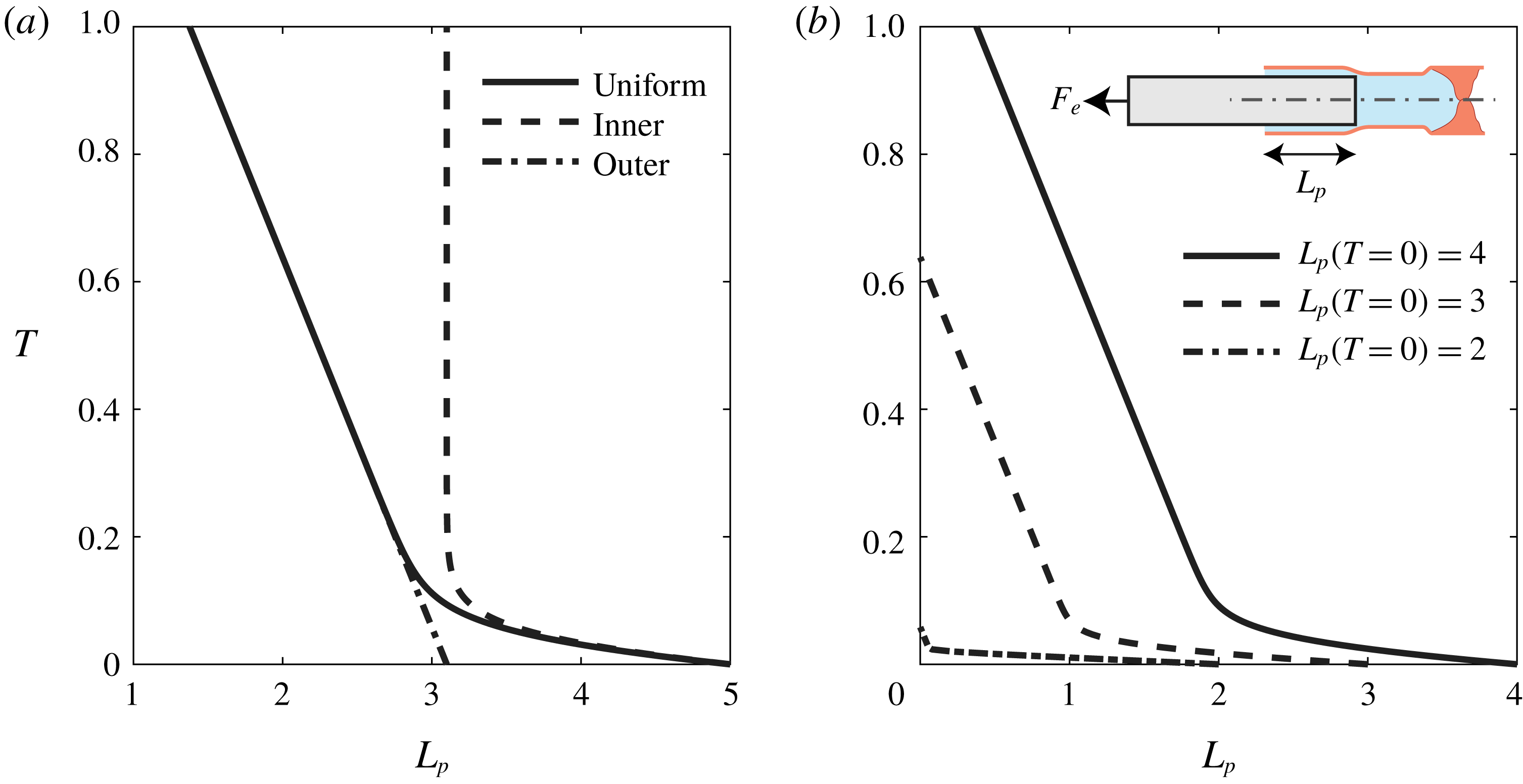
The uniform solution is plotted in figure 6 for several configurations. In all cases, the parameters of
 $\unicode[STIX]{x1D700}_{t}=0.1$
,
 $K=0.3$
and
 $F_{e}=-1.9$
(corresponding to
 $\unicode[STIX]{x1D700}_{NC}=0.05$
) are used. Figure 6(a) presents the motion of the cylinder for the initial conditions
 $L_{p}(T=0)=5$
(smooth line), along with the inner solution (dashed line) and outer solution (dashed-dotted line). After the initial inner dynamics, the singular effect of the near-contact dominates the motion and creates a steady extraction speed independent of
 $L_{p}$
. Panel (b) presents various initial values of
 $L_{p}(T=0)$
, showing that the inner region changes with
 $L_{p}(T=0)$
, but not the extraction speed of the outer region. For the case of
 $L_{p}(T=0)=2\approx -F_{e}$
, we see that the total extraction from the tube occurs before reaching the outer region. In this case, the distance required to completely extract the cylinder is too short, and does not create sufficient pressure reduction in order to reach near-contact dynamics.
The location of the cylinder within the tube
 $L_{p}$
versus time
 $T$
for the near-contact limit. All configurations are defined by
 $\unicode[STIX]{x1D700}_{t}=0.1$
,
 $K=0.3$
and
 $F_{e}=-1.9$
(corresponding to
 $\unicode[STIX]{x1D700}_{NC}=0.05$
). In panel (a)
 $L_{p}(T=0)=5$
and the different elements of the composite expansion are presented. Panel (b) presents various initial values of
 $L_{p}(T=0)$
.

5.2 Contact
$f_{e}<-2\unicode[STIX]{x03C0}Ewh_{0}r_{p}^{2}/r_{i}^{2}$

Equation (5.20) indicates that for
 $F_{e}<-2$
(or in dimensionless form
 $f_{e}<-2\unicode[STIX]{x03C0}Ewh_{0}r_{p}^{2}/r_{i}^{2}$
), there will be contact between the inner cylinder and the outer elastic tube. In such a case, additional forces will be applied at
 $\tilde{Z}=0$
, as illustrated in figure 5(b), which will modify the system dynamics. The contact prevents fluid from exiting the tube, and applies normal and tangential forces on the elastic tube. Thus, the outer-region governing equations are simply
 $$\begin{eqnarray}L_{p}-L_{p}(0)=\int _{1-\unicode[STIX]{x1D700}_{l}L_{p}}^{1}D_{r}\,\text{d}X\end{eqnarray}$$
and
 $$\begin{eqnarray}F_{e}-P|_{X=\unicode[STIX]{x1D700}_{l}L_{p}}+F_{z}=0,\end{eqnarray}$$
where
 $F_{z}=f_{z}/f_{e}^{\ast }$
is the additional force due to drag in the
 $\tilde{Z}$
direction, and using the scaling used in § 5.1 (
 $d_{r}^{\ast }=h_{0}$
,
 $l_{p}^{\ast }=2r_{i}h_{0}l/r_{p}^{2}$
,
 $p^{\ast }=Ewh_{0}/r_{i}^{2}$
and
 $f_{e}^{\ast }=\unicode[STIX]{x03C0}r_{p}^{2}p^{\ast }$
).
In dimensional terms, the friction force
 $f_{z}=q_{t}\cos \unicode[STIX]{x1D6FC}-q_{0}\sin \unicode[STIX]{x1D6FC}$
, where
 $\tan \unicode[STIX]{x1D6FC}=-(\unicode[STIX]{x2202}d_{r}/\unicode[STIX]{x2202}x)|_{x=l_{p}}$
. Since
 $\unicode[STIX]{x1D6FC}\ll 1$
, we can approximate
 $\unicode[STIX]{x1D6FC}\approx -(\unicode[STIX]{x2202}d_{r}/\unicode[STIX]{x2202}x)|_{x=l_{p}}$
and obtain
 $$\begin{eqnarray}f_{z}=2\unicode[STIX]{x03C0}r_{i}q_{0}\left(\unicode[STIX]{x1D707}_{f}+\frac{\unicode[STIX]{x2202}d_{r}}{\unicode[STIX]{x2202}x}\bigg|_{x=l_{p}}\right),\end{eqnarray}$$
where
 $\unicode[STIX]{x1D707}_{f}$
is the Coulomb friction coefficient, such that
 $q_{t}=\unicode[STIX]{x1D707}_{f}q_{0}$
. Calculation of the normal force acting on the elastic tube,
 $q_{0}$
, is obtained from the requirement of
 $d_{r}|_{x=l_{p}}=-h_{0}$
, where the deformation
 $d_{r}|_{x=l_{p}}$
is given by
 $$\begin{eqnarray}d_{r}|_{x=l_{p}}=-q_{0}\frac{r_{i}^{2}}{Ew}\left(\frac{3(1-\unicode[STIX]{x1D708}^{2})}{16w^{2}r_{i}^{2}}\right)^{1/4}+p|_{x=l_{p}}\frac{r_{i}^{2}}{2Ew}\end{eqnarray}$$
representing the linear summation of the deformation due to a localized normal force
 $q_{0}$
(first right-hand side term, Timoshenko & Woinowsky-Krieger (Reference Timoshenko and Woinowsky-Krieger1959)) and the deformation due to liquid pressure (second right-hand side term, see (5.20)).
We now calculate the normal force
 $q_{0}$
by requiring
 $d_{r}|_{x=l_{p}}=-h_{0}$
in (5.31). The obtained
 $q_{0}$
is substituted into (5.30), along with
 $\unicode[STIX]{x2202}d_{r}\unicode[STIX]{x2202}x|_{x=l_{p}}$
calculated from (5.21) (the localized force creates a symmetrical deformation, and does not affect the slope). This procedure yields the dimensional friction force
 $f_{z}$
as
 $$\begin{eqnarray}f_{z}\approx -\frac{2\unicode[STIX]{x03C0}Ew}{r_{i}}\left(h_{0}+p|_{x=l_{p}}\frac{r_{i}^{2}}{2Ew}\right)\left(\unicode[STIX]{x1D707}_{f}\left(\frac{64w^{2}r_{i}^{2}}{12(1-\unicode[STIX]{x1D708}^{2})}\right)^{1/4}+p|_{x=l_{p}}\frac{r_{i}^{2}}{Ew}\right)\end{eqnarray}$$
or in normalized form,
 $F_{z}$
, as
 $$\begin{eqnarray}F_{z}=-2\left(1+\frac{P|_{X=\unicode[STIX]{x1D700}_{l}L_{p}}}{2}\right)(\hat{\unicode[STIX]{x1D6F1}}_{1}+\hat{\unicode[STIX]{x1D6F1}}_{2}P|_{X=\unicode[STIX]{x1D700}_{l}L_{p}}),\end{eqnarray}$$
where
 $$\begin{eqnarray}\hat{\unicode[STIX]{x1D6F1}}_{1}=\frac{\unicode[STIX]{x1D707}_{f}}{r_{p}^{2}}\left(\frac{16w^{2}r_{i}^{6}}{3(1-\unicode[STIX]{x1D708}^{2})}\right)^{1/4},\quad \hat{\unicode[STIX]{x1D6F1}}_{2}=\frac{r_{i}h_{0}}{r_{p}^{2}}.\end{eqnarray}$$
The obtained dimensionless ratios
 $\hat{\unicode[STIX]{x1D6F1}}_{1}$
and
 $\hat{\unicode[STIX]{x1D6F1}}_{2}$
are geometrically small parameters, and thus friction does not have a leading-order effect on the system dynamics. For consistency, since terms of similar orders were previously neglected,
 $\hat{\unicode[STIX]{x1D6F1}}_{2}$
is neglected hereafter. However, for some configurations
 $\hat{\unicode[STIX]{x1D6F1}}_{1}\gg \hat{\unicode[STIX]{x1D6F1}}_{2}$
. Keeping
 $O(\hat{\unicode[STIX]{x1D6F1}}_{1})$
terms yields expressions for the fluid pressure ahead of the cylinder
 $$\begin{eqnarray}P|_{X>\unicode[STIX]{x1D700}_{l}L_{p}}=\frac{F_{e}-2\hat{\unicode[STIX]{x1D6F1}}_{1}}{1+\hat{\unicode[STIX]{x1D6F1}}_{1}}\end{eqnarray}$$
and the outer-region penetration length
 $$\begin{eqnarray}L_{p}=L_{p}(0)+\frac{F_{e}-2\hat{\unicode[STIX]{x1D6F1}}_{1}}{1+\hat{\unicode[STIX]{x1D6F1}}_{1}}.\end{eqnarray}$$
Thus, friction effects are of the order of the small parameter
 $\hat{\unicode[STIX]{x1D6F1}}_{1}$
, and only slightly reduce the liquid pressure and the penetration length
 $L_{p}$
. Following a similar asymptotic matching procedure to that presented in § 5.1, the uniform solution for contact is given by
 $$\begin{eqnarray}\displaystyle & & \displaystyle L_{p,uniform}=(L_{p}(0)+\hat{F}_{e})\nonumber\\ \displaystyle & & \displaystyle \qquad \times \,\left\{1+W\left[-\frac{1}{L_{p}(0)+\hat{F}_{e}}\exp \left(-1-\frac{\hat{T}-(\hat{F}_{e}+L_{p}(0))\ln (\hat{F}_{e})-L_{p}(0)}{L_{p}(0)+\hat{F}_{e}}\right)\right]\right\},\nonumber\\ \displaystyle & & \displaystyle\end{eqnarray}$$
where
 $\hat{F}_{e}=(F_{e}-2\hat{\unicode[STIX]{x1D6F1}}_{1})/(1+\hat{\unicode[STIX]{x1D6F1}}_{1})$
and
 $\hat{T}=t/t_{shear}^{\ast }$
(where
 $t_{shear}^{\ast }$
is defined in (5.12)).
The uniform solution (5.37) reaches a steady state of
 $L_{p}\rightarrow L_{p}(0)+\hat{F}_{e}$
. If
 $L_{p}(0)+\hat{F}_{e}<0$
, the steady-state solution is not physical, indicating that the inner cylinder completely exits the tube. Thus, steady-state contact will lock the inner cylinder within the elastic tube only for the range of forces
 $$\begin{eqnarray}2\hat{\unicode[STIX]{x1D6F1}}_{1}-L_{p}(0)(1+\hat{\unicode[STIX]{x1D6F1}}_{1})<F_{e}<-2.\end{eqnarray}$$
Outside of this range, the inner cylinder will exit the tube either due to fluid entering the tube
 $F_{e}>-2$
or sliding while in contact
 $F_{e}\leqslant 2\hat{\unicode[STIX]{x1D6F1}}_{1}-L_{p}(0)(1+\hat{\unicode[STIX]{x1D6F1}}_{1})$
. (In the dimensional force, and omitting the small
 $O(\hat{\unicode[STIX]{x1D6F1}}_{1})$
terms, this range is given by
 $-\unicode[STIX]{x03C0}r_{p}^{4}Ewl_{p}(0)/2r_{i}^{3}l<f_{e}<-2\unicode[STIX]{x03C0}Ewh_{0}r_{p}^{2}/r_{i}^{2}$
.)
The results presented in this subsection will be discussed further in the following section, summarizing the nonlinear extraction section § 5.
5.3 Summary of extraction dynamics
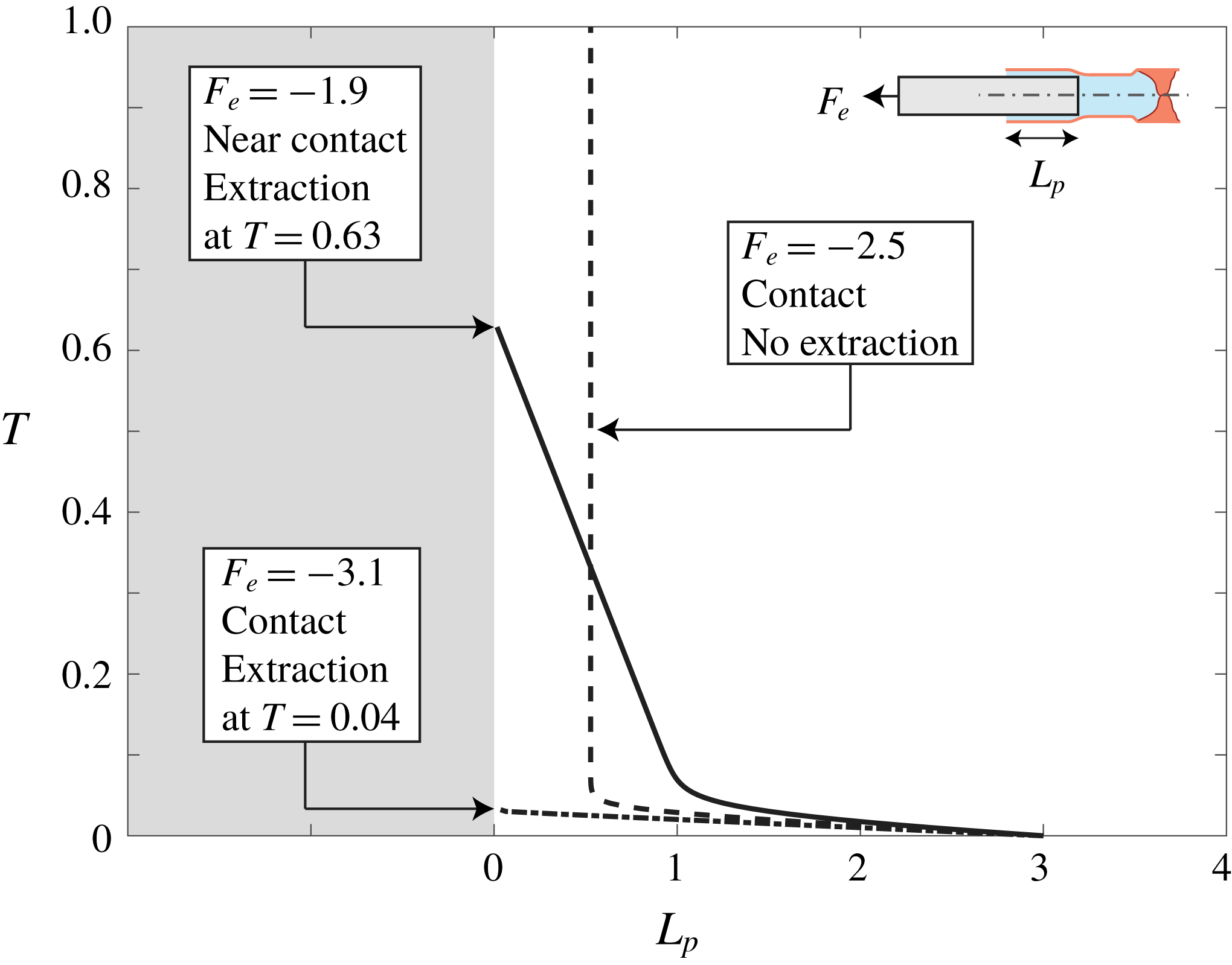
Figure 7 summarizes the different dynamics obtained for the case of nonlinear extraction. For near contact (smooth line,
 $F_{e}>-2$
) the viscous resistance in the region near
 $\tilde{Z}=0$
is singular and determines the liquid mass flux, and thus the motion of the inner cylinder. After a shear-dominant early dynamics (which occurs for all cases), the cylinder moves at constant speed due to the steady conditions near
 $\tilde{Z}=0$
. Increasing the extraction force to
 $2\hat{\unicode[STIX]{x1D6F1}}_{1}-L_{p}(0)(1+\hat{\unicode[STIX]{x1D6F1}}_{1})<F_{e}<-2$
creates steady-state contact (dashed line) in which the extraction force is balanced by the force due to liquid pressure at a constant penetration length
 $L+p=L_{p}(0)+(F_{e}-2\hat{\unicode[STIX]{x1D6F1}}_{1})/(1+\hat{\unicode[STIX]{x1D6F1}}_{1})$
. Friction creates only weak
 $O(\hat{\unicode[STIX]{x1D6F1}}_{1})$
effects. Extracting the tube with a greater force
 $F_{e}\leqslant 2\tilde{\unicode[STIX]{x1D6F1}}_{1}-L_{p}(0)(1+\hat{\unicode[STIX]{x1D6F1}}_{1})$
completely removes the inner cylinder from the tube before a steady state can be reached (dashed-dotted line), and thus lockage of the inner cylinder is limited to a specific range of extraction forces.
Extraction dynamics for near-contact (smooth line,
 $F_{e}>-2$
), locked contact (dashed line,
 $2\hat{\unicode[STIX]{x1D6F1}}_{1}-L_{p}(0)(1+\hat{\unicode[STIX]{x1D6F1}}_{1})<F_{e}<-2$
) and extracted contact (dashed-dotted line,
 $F_{e}\leqslant 2\hat{\unicode[STIX]{x1D6F1}}_{1}-L_{p}(0)(1+\hat{\unicode[STIX]{x1D6F1}}_{1})$
) configurations. For
 $F_{e}<-2$
, the negative gauge pressure reduces, but does not eliminate, the gap between the cylinder and the tube. Pressure-driven flow through this gap allows for the gradual extraction of the inner cylinder. For
 $2\hat{\unicode[STIX]{x1D6F1}}_{1}-L_{p}(0)(1+\hat{\unicode[STIX]{x1D6F1}}_{1})<F_{e}<-2$
, after an initial transient motion, the cylinder is locked within the tube and negative gauge pressure creates contact between cylinder and the tube. Thus, there is no flow, and the inner cylinder is locked at a constant location in which there is a balance between the external force, friction and the negative gauge pressure. Finally, for
 $F_{e}\leqslant 2\hat{\unicode[STIX]{x1D6F1}}_{1}-L_{p}(0)(1+\hat{\unicode[STIX]{x1D6F1}}_{1})$
, the inner cylinder is extracted in the initial transient motion. For all presented cases
 $K=0.3$
,
 $L_{p}(0)=3$
,
 $\unicode[STIX]{x1D700}_{t}=0.01$
and
 $\hat{\unicode[STIX]{x1D6F1}}_{1}=0.1$
.

6 Discussion and concluding remarks
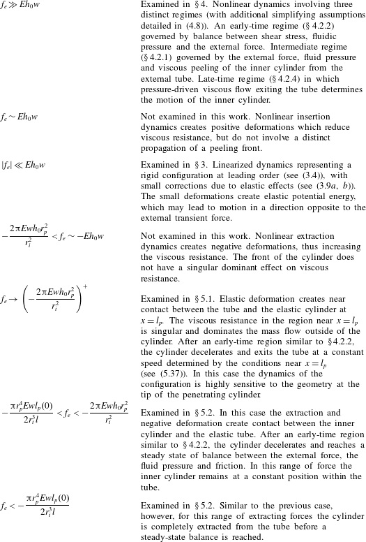
This work studied the low Reynolds number fluid mechanics of a basic configuration, consisting of a slender cylinder inserted into a fluid-filled elastic tube, which is relevant to various minimally invasive medical procedures. Governing integro-differential equations were derived by applying the lubrication approximation and a thin shell elastic model. Solutions for various limits were obtained by scaling analysis and regular and singular asymptotic schemes. Table 1 summarizes the different regions with regard to the value of
 $f_{e}$
, the external force acting to extract or insert the cylinder from or into the tube. In addition, table 1 presents comments and descriptions on the dominant mechanisms in regions with no approximate solutions.
Summary of results for different values of
 $f_{e}$
, the external insertion or extraction force.

The results presented in this work lay the foundation to model a wide range of minimally invasive medical procedures in which catheterization is the primary access method into the blood vessel or tissue. These include endoscopic interventions, such as cardiovascular and cerebrovascular interventions (among others such as arthroscopic or laparoscopic interventions), in which diagnostic and therapeutic catheters are used to access an area of interest in the heart or brain. In general, when performing such medical procedures the selected guidewire characteristics (e.g. core diameter, tip design and tapers) and their relation to the arterial geometry being accessed are largely based on previous trial and error and clinical success/failure statistics. As a result, many clinical procedures have a set of practical limitations, such as the requirement for absolute free movement of guidewire tips and avoiding of tip contact, or the maximal allowed external force. The analyses presented in the current work provide insight into the mechanics behind the catheter–artery coupling beyond statistical trial, and may help guide the design of future minimally invasive procedures. For example, the presented solutions of
 $l_{p}(t)$
can be viewed as a basic model for catheter navigation. In addition, the results allow for understanding of the dynamics of the distal end pressure during catheterization, which can be directly linked to coronary pressure measurements and the effects of lesion geometry on catheter tip pressure drop. The results we present can be used to estimate how fast one can extract a catheter without applying excessive stress on the skin, or how distal end pressure is affected by catheter insertion speed and, ultimately, that catheter extraction sometimes requires less force than the static steady-state force being applied.
In order to relate our results to a specific medical procedure, the non-dimensional parameters must be fitted to the relevant medical data. These include direct parameters, such as characteristic inserted catheter length,
 $l_{p}^{\ast }$
, or tissue compliance,
 $p^{\ast }/d_{r}^{\ast }$
, as well as more complex parameters, such as the peeling or shear time scales,
 $t^{\ast }$
, which may control the dynamics of the solution,
 $l_{p}(t),p(\tilde{z}=0)$
and are a function of the applied force, compliance, catheter/artery geometry and blood viscosity. Having stated the above, we emphasize that surgical settings include a multitude of effects, in addition to those examined in the current work, such as three-dimensional effects, torsional actuation, elastic effects (e.g. artery shear modulus) and more complex catheter geometry and elasticity. The specific set of features related to a particular minimally invasive procedure must be the subject of future work focused on a more specific configuration.
Appendix A. Derivation of the governing equations of motion
In this section we present the derivation of the governing equations of motion (2.8)–(2.10). We start with integral mass conservation of the system which takes the dimensional form
 $$\begin{eqnarray}\unicode[STIX]{x03C0}r_{p}^{2}(l_{p}-l_{p}(0))-\int _{0}^{l}2\unicode[STIX]{x03C0}r_{i}d_{r}\,\text{d}x+v_{q}=0,\end{eqnarray}$$
corresponding to (2.9). The first term in (A 1) is the volume of liquid displaced by the advancing cylinder, the second term is the volume change due to solid deformation and the last term is the total volume of the liquid which exited the system through the annular inlet. The combined Couette–Poiseuille flow profile in the annular gap due to the piston’s motion and the fluidic pressure inside the shell is given in Cartesian form by
 $$\begin{eqnarray}u=\frac{1}{2\unicode[STIX]{x1D707}}\frac{\unicode[STIX]{x2202}p}{\unicode[STIX]{x2202}x}(r^{2}-(r_{p}+r_{i})r+r_{i}r_{p})+\left(\frac{r_{i}+d_{r}-r}{h_{0}+d_{r}}\right)\frac{\unicode[STIX]{x2202}l_{p}}{\unicode[STIX]{x2202}t},\end{eqnarray}$$
(see also (3.32) of Elbaz & Gat (Reference Elbaz and Gat2016)). Thus, the volumetric flow rate is given by
 $$\begin{eqnarray}\dot{q}=\int _{r_{p}}^{r_{i}+d_{r}}u\cdot 2\unicode[STIX]{x03C0}r\,\text{d}r\sim \int _{r_{p}}^{r_{i}+d_{r}}u\,\text{d}r\cdot 2\unicode[STIX]{x03C0}r_{p}=\unicode[STIX]{x03C0}r_{p}(h_{0}+d_{r})\frac{\unicode[STIX]{x2202}l_{p}}{\unicode[STIX]{x2202}t}+\frac{\unicode[STIX]{x2202}p}{\unicode[STIX]{x2202}\tilde{z}}\frac{(h_{0}+d_{r})^{3}\unicode[STIX]{x03C0}r_{p}}{6\unicode[STIX]{x1D707}},\end{eqnarray}$$
and the volume of the liquid
 $v_{q}$
is
 $$\begin{eqnarray}v_{q}=\int _{0}^{t}\dot{q}\,\text{d}\tilde{t}=\unicode[STIX]{x03C0}r_{p}\int _{0}^{t}\frac{\unicode[STIX]{x2202}l_{p}}{\unicode[STIX]{x2202}\tilde{t}}(h_{0}+d_{r})\,\text{d}\tilde{t}+\frac{\unicode[STIX]{x03C0}r_{p}}{6\unicode[STIX]{x1D707}}\left(\int _{0}^{t}\frac{\unicode[STIX]{x2202}p}{\unicode[STIX]{x2202}\tilde{z}}(h_{0}+d_{r})^{3}\,\text{d}\tilde{t}\right).\end{eqnarray}$$
Noting that
 $r_{i}/r_{p}=1+O(\unicode[STIX]{x1D706}_{h}\unicode[STIX]{x1D700}_{3})$
, we neglect orders of
 $O(h_{0}/r_{i})$
, and the leading order of the general non-dimensional form of (A 1) becomes
 $$\begin{eqnarray}\displaystyle & & \displaystyle L_{p}-L_{p}(0)-\frac{2r_{i}d_{r}^{\ast }l}{r_{p}^{2}l_{p}^{\ast }}\left[\int _{0}^{1}D_{r}\,\text{d}X\right]+\frac{r_{p}l_{p}^{\ast }d_{r}^{\ast }}{r_{p}^{2}l_{p}^{\ast }}\left[\int _{0}^{T}\frac{\unicode[STIX]{x2202}L_{p}}{\unicode[STIX]{x2202}\tilde{T}}(\unicode[STIX]{x1D706}_{h}+D_{r})\,\text{d}\tilde{T}\right]\nonumber\\ \displaystyle & & \displaystyle \qquad +\,\frac{r_{p}{d_{r}^{\ast }}^{3}p^{\ast }t^{\ast }}{6{r_{p}}^{2}\unicode[STIX]{x1D707}{l_{p}^{\ast }}^{2}}\left[\int _{0}^{T}\frac{\unicode[STIX]{x2202}P}{\unicode[STIX]{x2202}\tilde{Z}}\frac{(\unicode[STIX]{x1D706}_{h}+D_{r})^{3}}{L_{p}}\,\text{d}\tilde{T}\right]=0.\end{eqnarray}$$
The gauge pressure at the inlet is zero. Then, using relation (2.7) we can substitute
 $D_{r}(X=0)=0$
into (A 5), and obtain (2.9),
 $$\begin{eqnarray}L_{p}-L_{p}(0)-\frac{2p^{\ast }l}{l_{p}^{\ast }E\unicode[STIX]{x1D700}_{2}}\left[\int _{0}^{1}D_{r}\,\text{d}X\right]+\frac{h_{0}^{3}p^{\ast }t^{\ast }}{6r_{p}\unicode[STIX]{x1D707}{l_{p}^{\ast }}^{2}}\left[\int _{0}^{T}\frac{\unicode[STIX]{x2202}P}{\unicode[STIX]{x2202}\tilde{Z}}(\tilde{Z}=1)\frac{1}{L_{p}}\,\text{d}\tilde{T}\right]=0.\end{eqnarray}$$
Next we turn to write a force balance on the piston,
 $$\begin{eqnarray}f_{e}(t)-\unicode[STIX]{x03C0}r_{p}^{2}p(\tilde{z}=0)+2\unicode[STIX]{x03C0}r_{p}\int _{0}^{l_{p}}\unicode[STIX]{x1D70F}_{xr}^{l}\,\text{d}\tilde{z}=0,\end{eqnarray}$$
where the first term is the external force, the second term is the pressure at the base of the piston (
 $\tilde{z}=0$
) and the third term is the shear stress on the piston wall (
 $r=r_{p}$
). Based on the velocity profile (A 2) the shear stress
 $\unicode[STIX]{x1D70F}_{xr}^{l}\sim \unicode[STIX]{x1D707}(\unicode[STIX]{x2202}u/\unicode[STIX]{x2202}r)$
is given by
 $$\begin{eqnarray}\unicode[STIX]{x1D70F}_{xr}^{l}=\frac{1}{2}\frac{\unicode[STIX]{x2202}p}{\unicode[STIX]{x2202}\tilde{z}}(h_{0}+d_{r})-\frac{\unicode[STIX]{x1D707}}{h_{0}+d_{r}}\frac{\unicode[STIX]{x2202}l_{p}}{\unicode[STIX]{x2202}t}.\end{eqnarray}$$
Substituting (A 8) back into (A 7), normalizing and neglecting orders of
 $O(d_{r}^{\ast }/r_{p})$
yields (2.10),
 $$\begin{eqnarray}F_{e}-\frac{\unicode[STIX]{x03C0}r_{p}^{2}p^{\ast }}{f_{e}^{\ast }}P(\tilde{Z}=0)-\frac{2\unicode[STIX]{x03C0}r_{p}\unicode[STIX]{x1D707}{l_{p}^{\ast }}^{2}}{d_{r}^{\ast }f_{e}^{\ast }t^{\ast }}\left[L_{p}\frac{\unicode[STIX]{x2202}L_{p}}{\unicode[STIX]{x2202}T}\int _{0}^{1}\frac{\text{d}\tilde{Z}}{\unicode[STIX]{x1D706}_{h}+D_{r}}\right]=0.\end{eqnarray}$$
We now adopt the dimensional evolution equation of axial creeping flow in the annular gap as given in (A1b) of Elbaz & Gat (Reference Elbaz and Gat2016),
 $$\begin{eqnarray}\frac{\unicode[STIX]{x2202}d_{r}}{\unicode[STIX]{x2202}t}-\frac{1}{12\unicode[STIX]{x1D707}}\frac{\unicode[STIX]{x2202}}{\unicode[STIX]{x2202}x}\left(\frac{\unicode[STIX]{x2202}p}{\unicode[STIX]{x2202}x}(h_{0}+d_{r})^{3}\right)+\frac{1}{2}\frac{\unicode[STIX]{x2202}l_{p}}{\unicode[STIX]{x2202}t}\frac{\unicode[STIX]{x2202}d_{r}}{\unicode[STIX]{x2202}x}=0.\end{eqnarray}$$
Normalizing (A 10) in accordance with (2.1)–(2.2) and noting that
 $\unicode[STIX]{x2202}\text{d}r/\unicode[STIX]{x2202}x=\unicode[STIX]{x2202}h/\unicode[STIX]{x2202}x$
, directly yields the governing evolution equation (2.8),
 $$\begin{eqnarray}\displaystyle \frac{\unicode[STIX]{x2202}D_{r}}{\unicode[STIX]{x2202}T}-\frac{t^{\ast }Ewh_{0}^{3}}{r_{i}^{2}12\unicode[STIX]{x1D707}l^{2}}\frac{\unicode[STIX]{x2202}}{\unicode[STIX]{x2202}X}\left[\frac{\unicode[STIX]{x2202}P}{\unicode[STIX]{x2202}X}\left(1+\frac{D_{r}}{\unicode[STIX]{x1D706}_{h}}\right)^{3}\right]+\frac{\unicode[STIX]{x1D700}_{l}\unicode[STIX]{x1D706}_{h}}{2}\frac{\unicode[STIX]{x2202}}{\unicode[STIX]{x2202}X}\left[\frac{\unicode[STIX]{x2202}L_{p}}{\unicode[STIX]{x2202}T}\left(1+\frac{D_{r}}{\unicode[STIX]{x1D706}_{h}}\right)\right]=0, & & \displaystyle\end{eqnarray}$$
where orders of
 $O(\unicode[STIX]{x1D706}_{h}\unicode[STIX]{x1D700}_{3})$
are neglected.