I. INTRODUCTION
Recently, multiple-input and multiple-output (MIMO) radars are extensively studied. One of the important subjects in MIMO radar study is the generation of orthogonal waveforms. Several schemes of waveform generation, such as the fast-time code-division multiple access (FT-CDMA), the slow-time CDMA (ST-CDMA), and the Doppler division multiple access (DDMA), are found in literatures [Reference Xue, Vu, Xu, Li and Stoica1, Reference Kantor and Davis2]. The TDMA and DDMA methods have high separation performance of transmitted waveforms; however, the Doppler and the spatial information are inevitably coupled. Correct target Doppler and spatial information is ambiguously resolved if the target Doppler is small or the pulse repetition frequency (PRF) is high enough. Therefore, those methods are more appropriate for short-range radars where high PRF is applicable. In [Reference Takayama, Tokieda and Sugawara3], we have proposed a scheme of waveform generation using the Gold-coded pulse. This scheme is categorized to the CDMA-based method both in the fast-time and the slow-time. The FT-CDMA method is free of the Doppler and space coupling; therefore, it is applicable for long-range radar application.
We have developed a prototype of an X-band sparse array imaging radar for long-range application. The radar is capable of operating in both the single-input–multiple-output (SIMO) mode and the MIMO mode. The MIMO mode is based on the CDMA method using the Gold-coded pulse waveforms, and a chirp pulse waveform is adopted for the SIMO mode. Both modes work on the same antenna array, which is composed of seven receivers (RX) evenly aligned with spacing of quasi-half-wavelength, and four transmitters (TX), which are evenly but sparsely aligned. Such sparse array radar gives the same array aperture as an equally sized array whose elements are aligned a half-wavelength apart with the virtual array technique.
In this paper, we clarify benefits of SIMO and MIMO radars, through theoretical and experimental comparisons between them using the hybrid SIMO and MIMO sparse array radar systems. Studies on the comparison between SIMO and MIMO in terms of target detectability are found in literatures [Reference Xue, Vu, Xu, Li and Stoica1, Reference Kantor and Davis2], but we will refer to more practical issues on the cost of computation, ease of array calibration, as well as target detectability. The paper is organized as follows. Section II presents an overview of the prototype radar system. Sections II and IV describe the schemes of waveform generation and signal processing for the SIMO and the MIMO modes, respectively. The MIMO ambiguity function with the Gold-coded waveforms is derived in Section V. Section VI presents a comparison of radar images acquired in the SIMO and MIMO modes. Finally, Section VII concludes this paper.
II. RADAR SYSTEM
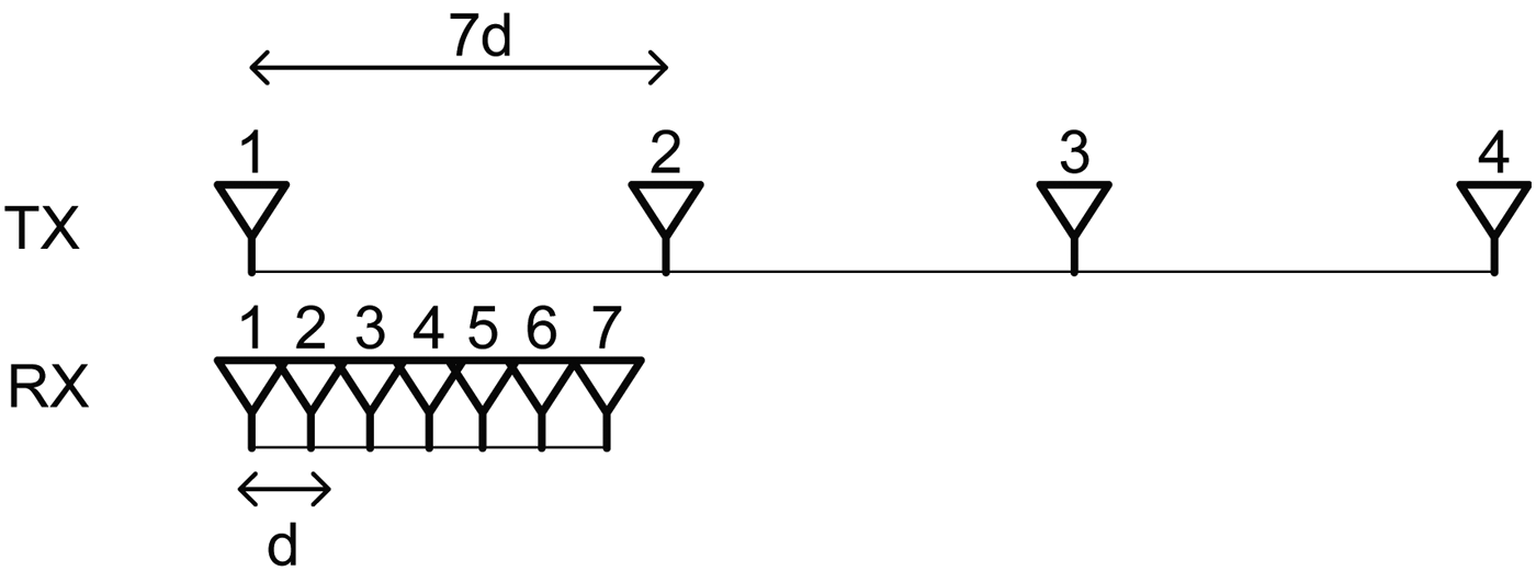
A photograph of the sparse array radar is shown in Fig. 1. For the generation and the acquisition of intermediate frequency (IF) waveforms digital components such as field programmable gate arrays (FPGAs), analog–digital converters (ADCs) and digital–analog converters (DACs), and a personal computer (PC) for the post-processing are inserted in the lower part of the system. Radio frequency (RF) components, such as X-band up-converters, down-converters, a local oscillator, and antenna arrays are mounted on the top part. The antenna is a uniform linear array, consisting of four TX channels and seven RX channels. The position of the TX and RX elements is illustrated in Fig. 2. The RX elements are aligned linearly with a spacing of quasi-half-wavelength d and the spacing of the TX elements is equal to the aperture of the RX array, 7d.
A prototype of the sparse array radar.

Antenna alignment of the prototype radar.
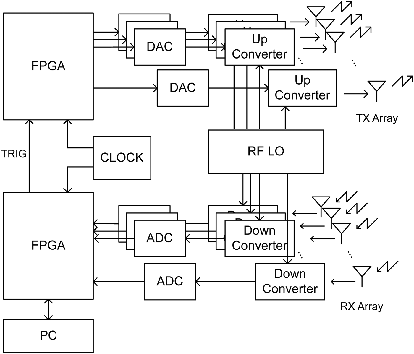
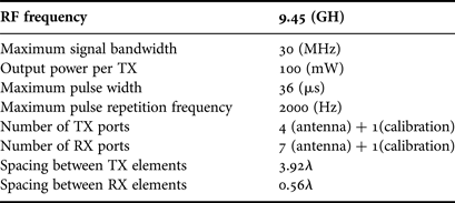
A block diagram of the radar system is illustrated in Fig. 3. Each TX has own up-converter and DAC connected to the FPGA. Arbitrary waveforms, which are programmed in the FPGA in advanced, are transmitted simultaneously. The RX channels also have own down-converter and ADC; therefore, the signals of all the channels can be acquired simultaneously. The digitized data are digitally down-converted from IF signal to baseband in-phase and quadrature (IQ) signal by the FPGA. The IQ data temporarily stored in the FPGA are sent to the PC for the post-processing. This system also has additional TX and RX ports for the calibration (the calibration ports are not explicitly shown in Fig. 3). These ports enable the monitoring of the temporal variation of channel gain and phase. The system parameters are summarized in Table 1.
System block diagram of the prototype.
System parameters.
III. SIMO MODE OPERATION
In the SIMO-mode operation, all the TX channels transmit unique but phase-scaled waveforms; therefore, the transmitted waveforms are beamformed to directions according to the amount of the phase modulation applied to TX channels. For example, a beam-pattern when all the TX channels are phase-aligned (equal in gain) is plotted with a rectangular-marked line in Fig. 4. Since the spacing between the TX array elements is seven times wider than that of the RX array, seven grating lobes are present, meaning that the waveform is transmitted to seven directions simultaneously (AZ0, 4, 8, …, 24). The azimuth ambiguity caused by the TX grating lobes is resolved by the RX beamforming. Since the spacing of the RX array is comparable to the half-wavelength, the RX beamforming is free of grating lobe. The result of the RX digital beamforming (DBF) steered to an azimuth of 0° is plotted in Fig. 4 with a dashed line. The resultant beam pattern is the multiplication of the TX and the RX beam pattern as plotted by a solid line as shown in Fig. 4. In this paper, we use the Fourier-based beamformer with appropriate weighting coefficients for simplicity.
Ideal azimuth beam pattern in the SIMO mode. TX beam pattern without window (marked by rectangular), RX beam pattern with the Kaiser window (dashed), and total beam pattern (solid). Radiation pattern of antenna elements is not taken into account.
Figure 5 shows the block diagram of the signal flow in the SIMO mode. In the following discussion, we use a chirp waveform (whose pulse-width and frequency bandwidth is 18.3 µs and 14 MHz, respectively) for the SIMO mode for a fair comparison with the waveform in the MIMO mode. In the TX side, the waveform is phase-modulated according to a desired direction of a beam before feeding to the antenna. The TX channel imbalance of gain and phase is calibrated at the same time. In the SIMO mode, the calibration error results in the spurious emission of radio wave to the unwanted direction; therefore, the calibration must be implemented before the transmission. Owing to non-linear property of power amplifiers, the array calibration requires iterative corrections of amplitude and phase until convergence. In the RX side, the digitized data are down-converted and the RX channel imbalance of gain and phase is calibrated. After the DBF, the beamformed data are pulse compressed with the transmitted chirp. Multiple pulses are transmitted sequentially and the Doppler information of a target is obtained in the following Doppler processing. Figure 6 shows the amount of phase modulation at each TX channel and pulse index in the SIMO mode operation. One measurement consists of 256 pulses, in which the first 64 consecutive pulses for seven directions (AZ0, 4, 8, …, 24), and the next 64 pulses for the next seven directions (AZ1, 5, 9, …, 25), and so on. At each pulse repetition, RX-beamformed outputs for the seven directions are computed simultaneously.
Block diagram of signal flow in the SIMO mode operation.
Amount of phase modulation of TX channel.
IV. MIMO-MODE OPERATION
In the MIMO-mode operation, a set of orthogonal waveforms is transmitted simultaneously. Among a number of schemes for the generation of a set of orthogonal waveforms, we have adopted the binary phase-shift-keyed waveforms modulated by a set of Gold codes as presented in [Reference Takayama, Tokieda and Sugawara3]. This scheme is categorized to the CDMA both in the fast-time and the slow-time. A chip length (0.07 µs) and a code length (255) of the Gold code are determined, so that its pulse compression gain is comparable to the chirp waveform in the SIMO mode. One difference from the SIMO mode is that such a set of orthogonal waveforms are not beamformed but radiated to whole the direction. This means that the scan rate is increased by M times, but there is a loss of the gain of 1/M, where M is the number of the TX channels. The MIMO mode, therefore, requires M times larger pulse integration time to make it comparable to the SIMO mode in terms of gain. For this reason, the pulse repetition number in the MIMO mode is determined to 255.
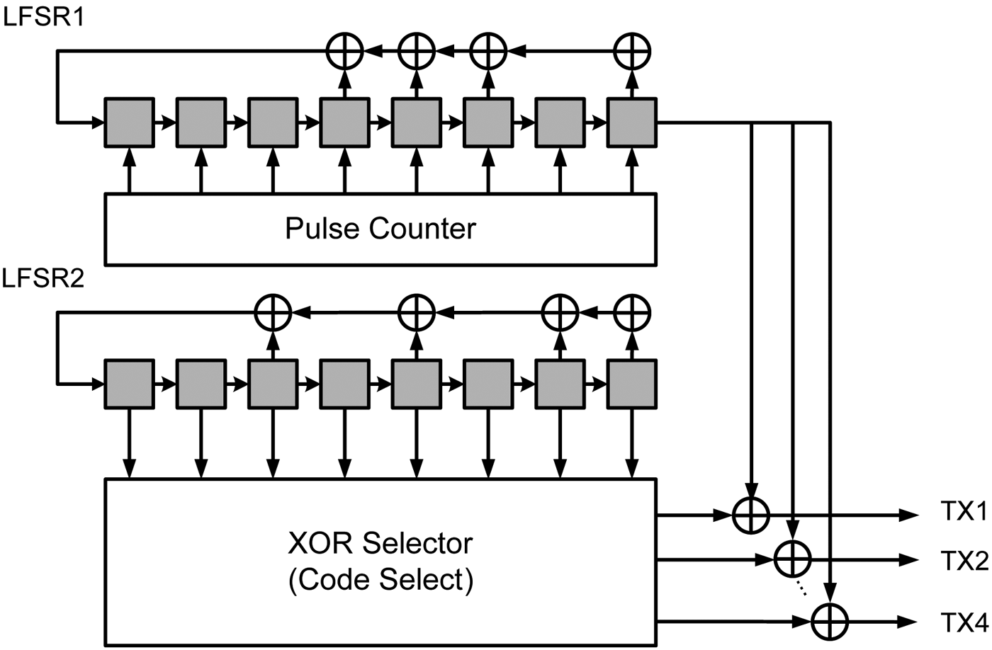
The Gold code is generated by linear feedback shift registers (LFSR) implemented in the FPGA as shown in Fig. 7. The exclusive-ored outputs of the XOR-selector outputs and the LFSR1 output is a set of Gold codes, which has small cross-correlation each other. Therefore, the transmitted waveforms are coded in the space and the fast-time. Additional coding is implemented in slow-time as well by incrementing the initial value of the LFSR1 at every pulse repetition, thereby, increase the orthogonality of waveforms.
Gold-code generator.
Figure 8 shows a block diagram of the signal flow in the MIMO mode. In the TX side, a set of Gold code is generated and fed to the TX channels. The TX array calibration before feeding signals to the TX channels is not necessary since the TX array calibration can be implemented on the received data. It eliminates the complexity of the TX array calibration which, in general, involves iterative correction of amplitude and phase due to the non-linear property of power amplifiers. In the RX side, the digitized data are down-converted and cross-correlated with the transmitted Gold codes to create virtual array signals. Since the Gold code is changed at every pulse repetition, the reference signals in the cross-correlation must be changed accordingly. The TX and RX calibrations are implemented simultaneously to the virtual array signals, since each of them is uniquely responsible to a TX and a RX channel. The virtual array signals are processed both in the space (DBF) and the slow-time (Doppler processing) to obtain the azimuth angle and velocity of targets.
Block diagram of signal flow in the MIMO mode operation.
One thing to note is that the increased degree of freedom (DoF) in both the space and the slow-time in MIMO compared with SIMO has advantage in the target detection performance at the risk of heavy burdens on the calculation. The number of the fast-time cross-correlation operation required in the MIMO mode at each pulse repetition is MN (N is the number of RX), which is M times larger than that of the SIMO mode. In the space (DBF) and the slow-time (Doppler) processing as well, the M times higher DoF requires the longer calculation time.
V. MIMO RADAR AMBIGUITY FUNCTION
The ambiguity function of MIMO radar is formulated in [Reference Chen and Vaidyanathan4, Reference San Antonio, Fuhrmann and Robey5]. In [Reference Chen and Vaidyanathan4], the ambiguity function for pulse MIMO radar with uniform linear array is derived. We will add slight modifications to [Reference Chen and Vaidyanathan4] to accommodate the MIMO waveforms and the processing flow described in Section IV.
Consider a target at (τ, ν, f), where τ is the delay, corresponding to the target range, ν is the Doppler frequency, and f is the normalized spatial frequency. The target signal in the nth RX is proportional to
 $$y_n^{\tau\comma \nu\comma f} \lpar t\rpar =\sum\nolimits_{m=0}^{M - 1} {u_m \left\{{\left({1+\displaystyle{\nu \over {f_c }}} \right)\, \lpar t - \tau \rpar } \right\}e^{j2\pi \nu \, t} e^{j2\pi \, f\lpar \gamma \, m+n\rpar } }\comma \;$$
where M is a number of TX channels, and N is a number of RX channels. f c is the center frequency of the waveforms. γ is the ratio between the TX and RX spacing defined by γ ≡ d T/d R·u m(t) is a radar waveform emitted by the mth TX and expressed as follows:
 $$u_m \lpar t\rpar =\sum\nolimits_{l=0}^{L - 1} {\varphi _{m\comma \, l} \lpar t - Tl\rpar }\comma \;$$
L is the total number of pulse repetition, and T is the pulse repetition interval, ϕm, l(t) is a waveform emitted by the mth TX at lth pulse repetition. For binary phase-shift coded pulses of a chip length, Δt, and a code length, Q, and ϕm, l(t) is expressed as
 $$\phi _{m\comma l} \lpar t\rpar =\sum\nolimits_{q=0}^{Q - 1} {e^{j\pi \, C_{m\comma q\comma \, l} } \, } s\lpar t - q\Delta t\rpar \comma \;$$
where
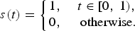 $$s\lpar t\rpar =\left\{{\matrix{ {1\comma \; } & {t \in \lsqb 0\comma \; 1\rpar \comma \; } \cr {0\comma \; } & {{\rm otherwise} .} \cr } } \right.$$
c m,q,l is the Gold code, which is generated as described in Section IV. Substituting (2) into (1), the target signal y nτ, ν, f(t) is approximated as,
 $$\eqalign{&y_n^{\tau\comma \nu\comma f} \lpar t\rpar \approx \cr &\quad \sum\nolimits_{m=0}^{M - 1} \sum\nolimits_{l=0}^{L - 1} \varphi _{m\comma l} \left(t - \tau - \left(1 + \displaystyle{\nu \over f_c} \right)Tl \right) e^{j2\pi \nu \, t} e^{j2\pi f\lpar \gamma \, m+n\rpar} \comma \;}$$
where we assume that the pulse envelope is not affected by the target Doppler under the assumption that
 $$Q \ll {{f_c } / \nu }.$$
A difference from the signal model in [Reference Chen and Vaidyanathan4] is that the range migration term is left to take into account the long pulse integration time.
In order to reduce the computation time, the correlation and the DBF and the Doppler processing described in Section IV are processed by the Fourier transformation on the assumption that a response of a target at (τ′, ν′, f′) can be independently processed in the delay, the space, and the Doppler domain, respectively. Therefore, the target response is modeled as follows:
 $$y_n^{\tau ^{\prime}\comma \nu ^{\prime}\comma f^{\prime}} \lpar t\rpar \approx \sum\nolimits_{m^{\prime}=0}^{M - 1} {\sum\nolimits_{l^{\prime}=0}^{L - 1} {\varphi _{m^{\prime}\comma \, l^{\prime}} \lpar t - \tau ^{\prime}\rpar } e^{j2\pi \nu ^{\prime}\, Tl} e^{j2\pi \, f^{\prime}\lpar \gamma \, m+n\rpar } }\comma \;$$
where, τ′, ν′, and f′ represent the assumed target delay, Doppler, and normalized spatial frequency, respectively. Compared to (4), the range migration term is neglected, and the phase modulation by the target Doppler is approximated by a step function, assuming that the phase modulation within a pulse is constant. Finally, the ambiguity function is expressed as,
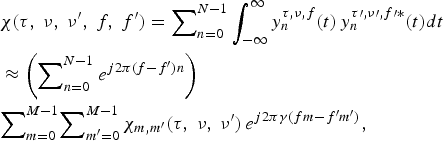 $$\eqalign{& \chi \lpar \tau\comma \; \nu\comma \; \nu ^{\prime}\comma \; f\comma \; f^{\prime}\rpar =\sum\nolimits_{n=0}^{N - 1} {\vint_{ - \infty }^\infty {y_n^{\tau\comma \nu\comma f} \lpar t\rpar \, y_n^{\tau \prime\comma \nu \prime\comma f \prime \ast}} \lpar t\rpar dt} \cr & \approx \left({\sum\nolimits_{n=0}^{N - 1} {e^{j2\pi \lpar f - f^{\prime}\rpar n} } } \right)\cr & {\sum\nolimits_{m=0}^{M - 1}} {\sum\nolimits_{m^{\prime}=0}^{M - 1} {\chi _{m\comma m^{\prime}}} \lpar \tau\comma \; \nu\comma \; \nu ^{\prime}\rpar } \, e^{j2 \pi \gamma \lpar fm - f^{\prime}m^{\prime}\rpar }\comma \; }$$
χm, m ′(τ, ν, ν′) is the cross-ambiguity function defined as
 $$\eqalign{& \chi_{m\comma m^{\prime}} \lpar \tau\comma \; \nu\comma \; \nu ^{\prime}\rpar \cr & \equiv \sum\nolimits_{l=0}^{L - 1} {\left({\vint_{0}^{T} {\varphi _{m\comma l} \left({t - \displaystyle{\nu \over {f_c }}Tl} \right)\, \varphi _{m^{\prime}\comma l} ^{\ast} \lpar t+\tau \rpar e^{j2\pi \nu \, t} \, } dt} \right)\, e^{ - j2\pi \lpar \nu - \nu ^{\prime}\rpar Tl} .} }$$
The delay τ in (8) and (9) is newly defined as the delay mismatch (difference between the true and assumed target delay). * in (8) and (9) stands for the complex conjugate. The radar ambiguity function in the MIMO case is, therefore, a function of five parameters: delay mismatch τ, target Doppler frequency ν and target normalized spatial frequency f, assumed Doppler frequency ν′and assumed normalized spatial frequency f′.
Figure 9 shows the MIMO ambiguity function at two-dimensional slices of interest. Figure 9(a) plots χ(τ, ν, ν′ = ν, f = 0, f′ = 0), representing how the range response of a target is distorted by the target Doppler frequency. The target Doppler frequency is normalized by a Doppler frequency, which makes one range-bin migration over the pulse integration time. As the target Doppler frequency increases, the range migration adversely affect on the loss of peak level, the spread of the range response, the increase of the sidelobe level.
The MIMO ambiguity function χ(τ, ν, ν′, f, f′) when the Gold code is used as TX waveforms as described in Section 4. (a) The distortion of the target range response by target Doppler χ(τ, ν, ν′ = ν, f = 0, f′ = 0), (b) The range and azimuth response for a zero-Doppler target χ(τ, ν = 0, ν′ = 0, f = 0, f′), (c) The sidelobe in the Doppler domain χ(τ, ν = 0, ν′, f = 0, f′ = 0).
The Gold-code generation scheme described in Section 4, has the following properties in the cross ambiguity function:
 $$\chi _{m\comma m^{\prime}} \lpar 0\comma \; 0\comma \; 0\rpar =\left\{{\matrix{ {LQ} & {\lpar m=m^{\prime}\rpar \comma \; } \cr { - 1} & {\lpar m \ne m^{\prime}\rpar \comma \; } \cr } } \right.$$
 $$E\left[{\left\vert {\chi _{m\comma m^{\prime}} \lpar \tau\comma \; 0\comma \; 0\rpar } \right\vert ^2 } \right]=Q\lpar \tau \ne 0\rpar.$$
The notation E[•] represents the expected value. It should be noted in (11) that due to the balanced property of the Gold code, the summation in terms of the pulse repetition number l in (9) gives no scaling in amplitude if the Doppler frequency is zero. The range sidelobe of the MIMO ambiguity function is the power ratio between the auto-correlation peak to the cross-correlation plus auto-correlation sidelobe; thus, the range sidelobe at the zero-Doppler frequency is derived by substituting (10) and (11) into (8),
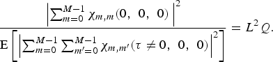 $$\displaystyle{{\left\vert {\sum\nolimits_{m=0}^{M - 1} {\chi _{m\comma m} \lpar 0\comma \; \, 0\comma \; \, 0\rpar \, } } \right\vert ^2 } \over {{\rm E}\left[{\left\vert {\sum\nolimits_{m=0}^{M - 1} {\sum\nolimits_{m^{\prime}=0}^{M - 1} {\chi _{m\comma m^{\prime}} \lpar \tau \ne 0\comma \; \, 0\comma \; \, 0\rpar } } } \right\vert ^2 } \right]}}=L^2 Q.$$
For a pulse repetition number of 255 and a code length of 255, it corresponds to the 72-dB peak-sidelobe level.
Figure 9(b) plots the ambiguity function at range and spatial frequency slice when the target and the assumed Doppler frequency is zero, χ(τ, ν = 0, ν′ = ν, f = 0, f′). For the summation of m and n in (8), the Taylor window (50 dB sidelobe) weighting is applied. The sidelobe in spatial frequency exactly matches to the impulse response of the window function and the sidelobe in the range is the same as Fig. 9(a) at zero-Doppler frequency (−72 dB). One of the advantages of MIMO radar over SIMO radar is the increased DoF in space. In the SIMO radar, the weigh is independently applied to the TX channels and the RX channels; therefore, the number of DoF is M + N − 2. In the MIMO radar, the weight is applied to the virtual array elements; therefore, the number of DoF is MN − 1.
The power ratio of the auto-correlation components and the cross-correlation components in the ambiguity function (8) at zero delay-mismatch is approximately,
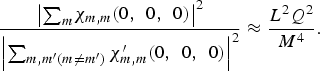 $$\displaystyle{\left\vert {\sum}_{m} \chi_{m\comma m} \lpar 0\comma \; \, 0\comma \; \, 0\rpar \right\vert^2 \over \left\vert \sum _{m\comma m^{\prime} \lpar m \ne m^{\prime}\rpar } \chi _{m\comma m} ^{\prime} \lpar 0\comma \; \, 0\comma \; \, 0\rpar \right\vert^2} \approx \displaystyle{L^2 Q^2 \over M^4}.$$
For a pulse repetition number of 255, a code length of 255 and a number of TX channels of 4, it corresponds to 72 dB. The cross-correlation term has little impact on the auto-correlation term and the sidelobe of the target response in the spatial frequency domain mainly depends on the beamforming weight.
Figure 9(c) plots range the ambiguity function χ(τ, ν = 0, ν′, f = 0, f′ = 0), representing the sidelobe level at off-the-target Doppler. If the Doppler frequency is not zero, the balanced property of the Gold code is not true, thus, the summation in (9) in terms of the pulse repetition number l has the same effect as the summation of random variables. The sidelobe in Doppler frequency is
 $$\displaystyle{{\left\vert {\sum\nolimits_{m=0}^{M - 1} {\chi _{m\comma m} \lpar 0\comma \; \, 0\comma \; \, 0\rpar } } \right\vert ^2 } \over {E\left[{\left\vert {\sum\nolimits_{m=0}^{M - 1} {\sum\nolimits_{m^{\prime}=0}^{M - 1} {\chi _{m\comma m^{\prime}} \lpar \tau \ne 0\comma \; \, 0\comma \; \, \nu ^{\prime} \ne 0\rpar } } } \right\vert ^2 } \right]}}=LQ.$$
For a pulse repetition number of 255, a code length of 255, it corresponds to 48 dB.
VI. COMPARISON BETWEEN SIMO AND MIMO
The radar prototype has been tested in an experiment in the SIMO and the MIMO mode operation. Data have been acquired at the roof of a building, which is located approximately at the height of 40 m from the ground. Targets are mostly structural objects such as buildings and power transmission towers that are located at a range from 100 m to 10 km from the observation point. In the SIMO mode as described in Section 3, a chirp signal was used and the phase modulation scheme as presented in Fig. 6 was applied to at each pulse repetition for the TX beamforming. In the MIMO mode as described in Section 4, the Gold codes were used. The SIMO mode operation requires the calibration of TX array in advance, which calibration requires iterative correction of gain and phase since high-power amplifiers are generally non-linear. The calibration in the MIMO mode, however, is easy since the TX and RX array adjustment is possible after data acquisition by software.
A comparison of radar images acquired by the SIMO and the MIMO mode is shown in Fig. 10. Since most of the targets are stationary, the zero-Doppler component is extracted. There is almost no difference in signal-to-noise ratio as the SIMO and the MIMO signal have the same pulse compression gain, the total output power. The azimuth patterns of a target located at a range of 3300 m is plotted in Fig. 11, in which the SIMO and the MIMO mode azimuth patterns are indicated by red and blue, respectively. Those azimuth patterns are similar to the estimated patterns shown in Figs 4 and 9(b). The difference between MIMO and SIMO results from the different weighting coefficients for the DBF. Degraded sidelobe compared with Figs 4 and 9(b) is due to the objects around the main target, or the array calibration error.
A comparison of radar images, SIMO mode (left), and MIMO mode (right).
A comparison of a target azimuth pattern, in the SIMO mode (dashed), and the MIMO mode (solid).
VII. CONCLUSION
A sparse array radar system that is capable of operating in both SIMO and MIMO modes has been developed. A comparison has been made between the SIMO mode with a chirp waveform and the MIMO mode with the Gold-coded pulse waveforms. Mutually complementary properties between the SIMO and MIMO modes in terms of the cost of computation, the ease of array calibration, and the detectability of targets are clarified through simulations and an experiment.
In terms of the calculation cost, the MIMO mode far exceeds the SIMO mode because of a larger number of correlation processing required, a larger azimuth DoF in the DBF processing, and longer pulse integration time in the Doppler processing.
From a point of view of the target detectability, however, larger spatial and Doppler DoF has potential of better discriminates targets. It should be noted, however, that in MIMO radar that is based on CDMA method, the cross-correlation components of orthogonal waveforms raise the range and the Doppler sidelobe level. The distortion of target response by the range migration also must be taken into account as the MIMO mode requires longer integration time compared with the SIMO mode.
In terms of the array calibration, the SIMO mode operation requires the prior-calibration of TX array in hardware, which calibration requires iterative correction of gain and phase since high-power amplifiers are generally non-linear. In contrast, the calibration in the MIMO mode is easily implemented as the TX array calibration is possible digitally after data acquisition. Moreover, the MIMO mode is more power efficient since all the TX elements can transmits its maximum power and adjusted after the data acquisition. On the other hand, in the SIMO mode, the TX power must be adjusted or weighed before transmission.
ACKNOWLEDGEMENT
This research is supported by R&D for Expansion of Radio Wave Resources, in Japan Ministry of Internal Affairs and Communications.
Takuya Takayama rceived his M.E. and Ph.D. degrees from Tohoku University, Sendai, Japan, in 2006 and 2009 respectively. Since 2009, he has been with Japan Radio Corporation, working on radar signal processing and system design. He received the EuMA Radar Prize at the 10th European Radar Conference in 2013.
Masayuki Sugano received his M.E. degree from Okayama University, Okayama, Japan in 2002. Since 2002, he has been in Japan Radio Corporation. His research interests are antenna and RF design and optimization for radar system.
Yukinobu Tokieda received his M.E. degree from Kumamoto University, Kumamoto, Japan in 1995. Since 1995 he has been in Japan Radio Corporation. His research interest includes radar signal processing and image processing.
Hiroki Sugawara received his B.E. degree from the Musashi Institute of Technology, Tokyo, Japan in 1985. Since 1985 he has been in Japan Radio Corporation. He is currently working as the head of Laboratory of Applied System. His interest is overall radar system design.