1. Introduction
The flow over a bluff body has attracted much interest because of its wide range of practical applications, including tall buildings, bridges, locomotives, submarine pipelines, etc. (Bearman Reference Bearman1984; Williamson Reference Williamson1996; Derakhshandeh & Alam Reference Derakhshandeh and Alam2019). It is of great theoretical and practical importance how to achieve drag reduction. Various strategies have been proposed to achieve drag reduction by controlling the boundary layer or wake vortex, and which are either passive (surface roughness, surface dimple, splitter plate, small secondary control cylinder) or active (rotary, rotary oscillation, time-periodic blowing/suction, a synthetic jet). Scholars have done a very good job of sorting out these methods (Choi, Jeon & Kim Reference Choi, Jeon and Kim2008; Rashidi, Hayatdavoodi & Esfahani Reference Rashidi, Hayatdavoodi and Esfahani2016; Chen et al. Reference Chen, Huang, Chen, Yu and Gao2022; Ran et al. Reference Ran, Deng, Yu, Chen and Gao2023).
When a circular cylinder rotates around its axis in a fluid flow, the rotating behaviour causes a pressure difference above and below the circular cylinder, and thus an increase in the average value of the lift coefficient, commonly known as the Magnus effect (Swanson Reference Swanson1961; Seifert Reference Seifert2012; Tillig & Ringsberg Reference Tillig and Ringsberg2020). Rotating a circular cylinder can effectively suppress vortex shedding. Prandtl (Reference Prandtl1925) experimentally measured the lift coefficient of a rotating cylinder placed in a uniform stream and claimed that the resulting lift coefficient had a maximum value of
 $4 \pi$
. Both the Reynolds number
 $Re = {\rho U_\infty D}/{\mu }$
and the dimensionless rotation rate
 $\alpha = {\Omega D}/{2U_\infty }$
have a significant effect on the flow past a rotating cylinder (Chang Reference Chang1992). The parameters
 $\rho$
,
 $U_\infty$
,
 $D$
,
 $\mu$
and
 $ \Omega$
are the flow density, free stream flow velocity, the diameter of the circular cylinder, the flow viscosity and the rotational speed of the circular cylinder, respectively.
As
 $\alpha$
increases from 0, the wake of the rotating circular cylinder undergoes complex changes, leading to the emergence of two crucial vortex shedding modes. To identify the range of dimensionless rotational speeds corresponding to the first vortex shedding mode, the critical rotational speed
 $\alpha _L$
is proposed: the vortex street in the wake of the cylinder resembles the von Kármán vortex street at
 $0\leqslant \alpha \leqslant \alpha _L$
, which is called the vortex shedding mode I, and then the vortex shedding completely disappears at
 $\alpha \geqslant \alpha _L$
(Stojković et al. Reference Stojković, Breuer and Durst2002; Pralits, Brandt & Giannetti Reference Pralits, Brandt and Giannetti2010). In vortex shedding mode I, as
 $\alpha$
increases from 0, the mean drag coefficient gradually decreases, while the mean lift coefficient increases almost linearly with
 $\alpha$
. The Strouhal number, which indicates the vortex shedding frequency, remains independent of the dimensionless rotational speed. The
 $\alpha _L$
exhibits a strong dependence on the Reynolds number. The
 $\alpha _L$
is approximately equal to 1.4, 1.8, 1.9 for
 $Re = 60$
, 100, 160 (Stojković et al. Reference Stojković, Schön, Breuer and Durst2003), 1.91 for
 $Re$
= 200 (Cheng, Liu & Lam 2001) and 2 for
 $Re = 1000$
(Chew, Cheng & Luo Reference Chew, Cheng and Luo1995). As
 $\alpha$
increases from the
 $\alpha _L$
, the flow around the rotating circular cylinder becomes steady and vortex shedding is completely suppressed. The force coefficients no longer fluctuate and become constant.
As
 $\alpha$
is further increased, the flow around the rotating cylinder becomes unsteady again and vortex shedding mode II appears. Vortex shedding occurs only from one side of the rotating circular cylinder. The force coefficients have much larger amplitudes and much lower frequencies. The rotational speed interval at which the vortex shedding mode II occurs is notably narrower than that (
 $0 \leqslant \alpha \leqslant \alpha _L$
) at which the shedding mode I appears. The rotational speed interval of
 $\alpha$
corresponding to the occurrence of vortex shedding mode II is
 $4.8 \leqslant \alpha \leqslant 5.15$
for
 $Re$
= 100 (Stojković et al. Reference Stojković, Schön, Breuer and Durst2003) and
 $4.34 \leqslant \alpha \leqslant 4.7$
for
 $Re$
= 200 (Cheng, Liu & Lam 2001). Kumar et al. (Reference Kumar, Lopez, Probst, Francisco, Askari and Yang2013) presented the experimental evidence for vortex shedding mode II for the flow over the circular cylinder with
 $\alpha = 4.45$
at
 $Re$
= 200 using flow visualisation and particle image velocimetry measurements. By studying the flow over a rotating circular cylinder with
 $0\leqslant \alpha \leqslant 6$
at
 $60 \leqslant Re \leqslant 200$
, Stojković et al. (Reference Stojković, Schön, Breuer and Durst2003) compiled a comprehensive bifurcation diagram
 $\alpha$
(
 $Re$
), which delineates the boundaries of the two vortex shedding modes in terms of vortex shedding frequency, the mean value and amplitudes of the force coefficients, interval of the rotational speed, etc.
In addition to the motion of rotating the circular cylinder, the motion of rotational oscillation of the circular cylinder can also control the unsteady wake flow, resulting in drag reduction. Tokumaru & Dimotakis (Reference Tokumaru and Dimotakis1991) investigated the effectiveness of sinusoidal rotation of the circular cylinder at
 $Re = 15\,000$
by using flow visualisation and wake profile measurements. The drag coefficient is reduced from 1.4 to 0.2, achieving a minimum drag reduction of 86%. Using two-dimensional numerical simulations over a wide range of Reynolds numbers of 150–15 000, Shiels & Leonard (Reference Shiels and Leonard2001) confirmed the observation of Tokumaru & Dimotakis (Reference Tokumaru and Dimotakis1991) of a remarkable decrease in drag at higher Reynolds numbers. The larger amplitude and frequency of the rotational oscillation triggering the formation of the multipole vorticity structure is effective to achieve the drag reduction at higher Reynolds numbers (
 $Re \geqslant 3000$
). The amount of drag reduction was strongly dependent on the Reynolds number. Choi, Choi & Kang (Reference Choi, Choi and Kang2002) reported a similar discovery, simulating two-dimensional flow past a sinusoidally rotating cylinder at
 $Re$
= 1000 and 100, and demonstrating mean drag reductions of 60
 $\%$
and 12.4
 $\%$
, respectively. It was shown that the minima of the mean drag and the amplitude of the lift fluctuations occur near the boundary between the lock-on and non-lock-on regions. Cheng, Liu & Lam (2001) conducted the numerical simulations about the flow over a rotationally oscillating circular cylinder at
 $Re$
= 200,
 $0\leqslant \alpha _m \leqslant 6$
and
 $0.5\leqslant f/f_0 \leqslant 3.0$
, where
 $\alpha _m$
is the maximum angular velocity,
 $f$
is the frequency of oscillation and
 $f_0$
is the natural vortex shedding frequency. The higher drag reduction can be obtained by increasing the maximum angular velocity
 $\alpha _m$
.
Similar to the rotating cylinder, the sphere rotates around its axis, again producing the Magnus effect. Considering the flow past a transversely rotating sphere, the flow and vortex structures undergo complex changes with increasing Reynolds number and dimensionless rotational speed. Using the Stokes and Ossen expansion, Rubinow & Keller (Reference Rubinow and Keller1961) derived an expression
 $C_L=2 \alpha$
for the lift coefficient acting on a transversely rotating sphere for
 $Re$
< 1. Here,
 $\alpha =\Omega D/2U_\infty$
is the non-dimensional rotation rate,
 $\Omega$
is the angular velocity,
 $D$
is the diameter of sphere and
 $U_\infty$
is the free stream velocity. Tsuji, Morikawa & Mizuno (Reference Tsuji, Morikawa and Mizuno1985) analysed the experimental data and provided an estimated expression
 $C_L=(0.40 \pm 0.10) \alpha$
for the lift coefficient, applicable to rotational speeds
 $\alpha \lt 0.7$
and
 $550 \leqslant Re \leqslant 1600$
. For additional lift coefficient models, refer to the related paper of Loth (Reference Loth2008). Giacobello, Ooi & Balachandar (Reference Giacobello, Ooi and Balachandar2009) investigated the flow past a transversely rotating sphere at Reynolds number
 $100 \leqslant Re \leqslant 300$
and
 $0 \leqslant \alpha \leqslant 1$
. For the same Reynolds number, Kim (Reference Kim2009) extends
 $\alpha$
from
 $0 \leqslant \alpha \leqslant 1$
to
 $0 \leqslant \alpha \leqslant 1.2$
, while Dobson, Ooi & Poon (Reference Dobson, Ooi and Poon2014) widens it further to
 $\alpha$
= 3. For flow past a transversely rotating sphere at
 $Re$
= 300, hairpin vortices are periodically shed from the sphere surface at
 $0 \leqslant \alpha \leqslant 0.3$
; the vortex shedding is suppressed and the wake reverts to a steady double thread at
 $0.5 \leqslant \alpha \leqslant 0.6$
. The flow enters the second vortex shedding regime caused by the shear layer instability
 $0.8 \leqslant \alpha \leqslant 2$
, the flow enters the ‘separatrix’ regime at
 $2.25 \leqslant \alpha \leqslant 3$
, and the drag coefficient first increases and then decreases as
 $\alpha$
increases from 0 to 3. In addition to the ‘vortex shedding’ regime and the ‘shear layer instability’ regime identified by previous researchers, Poon et al. (Reference Poon, Ooi, Giacobello, Iaccarino and Chung2014) discovered a new ‘shear layer-stable foci’ regime for
 $\alpha = 1$
at
 $Re$
= 500 and for
 $0.8 \leqslant \alpha$
at
 $640 \leqslant Re \leqslant 1000$
.
For flow past a rotating circular cylinder, the Magnus effect is known to be effective in reducing the drag while greatly enhancing the lift simultaneously. For flow past a rotating sphere, the Magnus effect enhances the drag and lift. In the present study, flow past a stationary bluff body is abbreviated as SB, flow past a rotating bluff body is abbreviated as RB and flow past a rotating bluff body with a stationary hood over the rear half of the bluff body is abbreviated as RBH. The analysis by the force element analysis (FEA, proposed by Chang Reference Chang1992, and Chang, Yang & Chu 2008 for multiple bodies) suggests that one may greatly reduce the drag with producing only a minimal lift for flow past a stationary circular cylinder and a negative lift for flow past a stationary sphere using RBH. In addition, the flow field stabilises gradually. It is shown that the drag coefficient can be reduced by 99
 $\%$
while the lift coefficient is very small, compared with the full Magnus effect. For flow past a stationary circular cylinder at
 $Re$
= 200, the amplitude of the force coefficient gradually approaches 0 and the flow field gradually becomes steady. For flow past a stationary sphere at
 $Re$
= 200 and
 $Re$
= 300, the amplitude of the force coefficients quickly approaches 0 and the flow field rapidly becomes steady.
This paper is organised as follows. Section 2 presents the physical problem and the method of analysis. Section 3 presents the drag reduction for flow past a circular cylinder or a sphere at moderately low Reynolds number. Section 4 summarises some concluding remarks.
2. Physical model and method of analysis
This section begins with a brief overview of FEA. This is followed by a description of the fundamental physical problem and numerical validation.
2.1. Brief overview of force element analysis
For flow past a rotating circular cylinder or a rotating sphere at moderately low Reynolds numbers, the fluid is assumed to have a constant density
 $\rho$
and a dynamic viscosity
 $\mu$
. To present the results concisely in non-dimensional form, we use the diameter
 $D$
of the circular cylinder or the sphere as the reference length, the incoming velocity
 $U_\infty$
at infinity as the reference velocity, the ratio
 ${D}/{U_\infty }$
as the reference time and
 $\rho U_\infty ^2$
as the reference pressure. The dimensionless rotational speed
 $\alpha$
is defined by
 $\alpha = {\Omega D}/{2U_\infty }$
, where
 $\Omega$
is the angular velocity. The fluid flow generated by the motion of the circular cylinder or the sphere is assumed to be governed by the incompressible Navier–Stokes equations, expressed in the dimensionless form,
 \begin{equation} \frac {\partial \boldsymbol {u}}{\partial t}+\boldsymbol {u}\cdot \nabla \boldsymbol {u}=-\nabla p + \frac {1}{Re}\nabla ^{2}\boldsymbol {u}, \end{equation}
and the continuity equation
 \begin{equation} \nabla \cdot \boldsymbol {u} = 0, \end{equation}
where
 $ \boldsymbol {u}$
and
 $p$
stand for the flow velocity and pressure,
 $Re = \rho U_\infty D/ \mu$
denotes the Reynolds number. The vorticity,
 $\boldsymbol {\omega } = \nabla \times \boldsymbol {u}$
, is another important quantity for later development.
In most of the literature (see White & Xue Reference White and Xue2021, p. 317), the drag coefficient
 $C_{D}$
and the lift coefficient
 $C_{L}$
are defined as
 \begin{equation} C_{D}=\dfrac {F_{D}}{\frac {1}{2}\rho U_\infty ^2 A_0} \end{equation}
and
 \begin{equation} C_{L}=\dfrac {F_{L}}{\frac {1}{2}\rho U_\infty ^2 A_0}. \end{equation}
Note that
 $F_{D}$
and
 $F_{L}$
denote the drag and lift, respectively. In two dimensions,
 $F_D$
is actually the force per unit span with the dimension force/length;
 $A_0=D$
and
 $A_0={\pi D^2}/4$
are the projection areas of the circular cylinder and the sphere, respectively. Each force component consists of pressure force and skin friction force. Let
 $\boldsymbol {i}$
and
 $\boldsymbol {j}$
denote the drag and lift directions, respectively. Since a factor of
 $\pi$
appears in the three-dimensional definition of
 $C_{D}$
and
 $C_{L}$
for the sphere, the drag coefficient
 $C_D$
and the lift coefficient
 $C_L$
exerted on a circular cylinder or a sphere can be expressed by
 \begin{equation} \gamma C_{D}=\int _{S_{0}}p(\boldsymbol {n}\cdot \boldsymbol {i})\mathrm {d}A+\frac {1}{Re}\int _{S_{0}}(\boldsymbol {n}\times \boldsymbol {\omega })\cdot \boldsymbol {i}\mathrm {\,d}A \end{equation}
and
 \begin{equation} \gamma C_{L}=\int _{S_{0}}p(\boldsymbol {n}\cdot \boldsymbol {j})\mathrm {d}A+\frac {1}{Re}\int _{S_{0}}(\boldsymbol {n}\times \boldsymbol {\omega })\boldsymbol {\cdot }\boldsymbol {j}\mathrm {\,d}A. \end{equation}
Here,
 $\gamma =0.5$
for the circular cylinder and
 $\gamma =\pi /8$
for the sphere,
 $S_{0}$
is the surface of the circular cylinder or the sphere, and
 $\boldsymbol {n}$
is the unit normal vector pointing from the fluid towards the body.
In this study, an alternative method to obtain the drag coefficient
 $C_{D}$
is the FEA proposed by Chang (Reference Chang1992). In the derivation, an auxiliary potential function
 $\phi _i$
is employed to satisfy the Laplace equation,
 \begin{equation} \nabla ^{2}\phi _{i}=0, \end{equation}
and boundary conditions,
 \begin{equation} \nabla \phi _{i}\cdot \boldsymbol {n}=-\boldsymbol {i}\cdot \boldsymbol {n}, \quad \boldsymbol {r} \; \mbox {on} \; S_{0}, \end{equation}
 \begin{equation} \phi _{i}=0,\quad \boldsymbol {r} \rightarrow \infty . \end{equation}
Equations (2.7)–(2.9) show that
 $\phi _i$
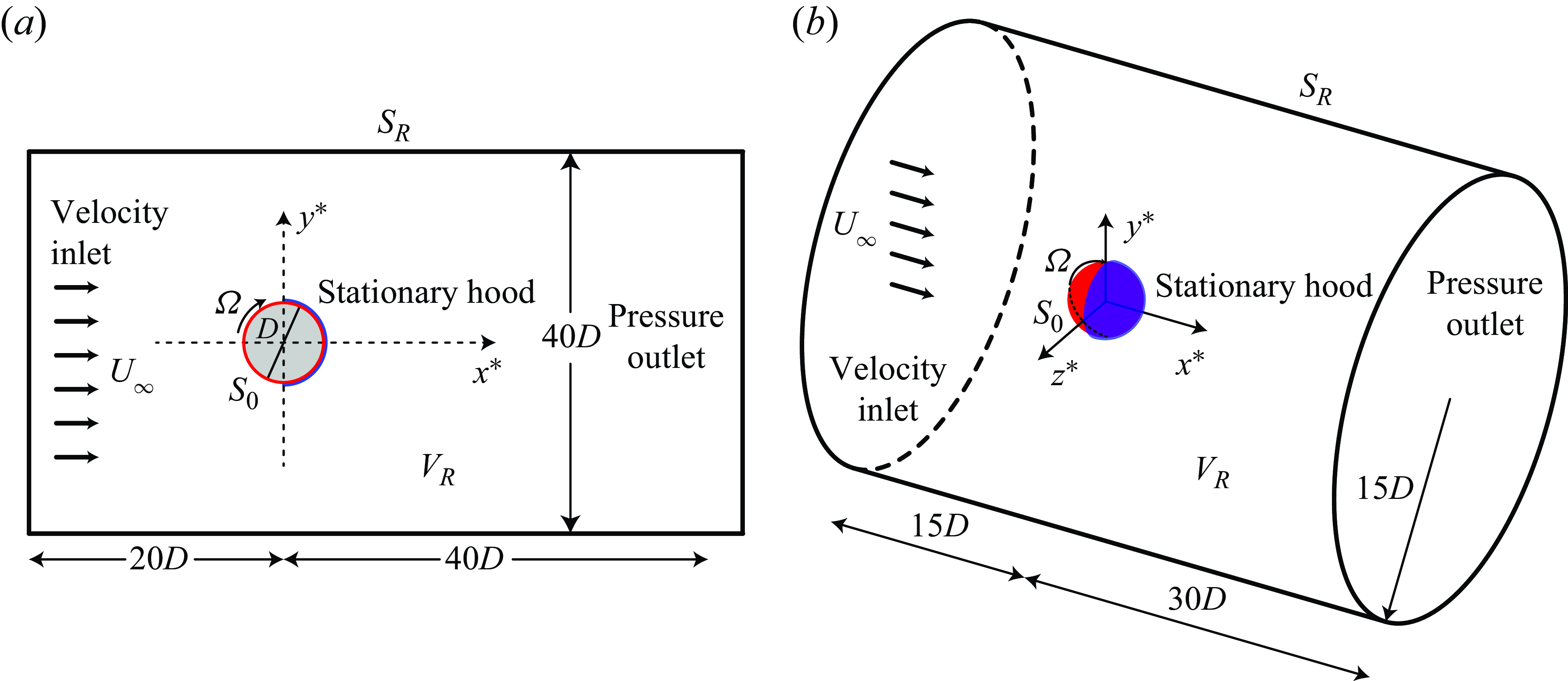
represents the potential flow generated by the motion of the circular cylinder or the sphere with unit velocity in the negative drag direction. In this study, we have numerically solved (2.7) within the domain
 $V_R$
depicted in figure 1. Let
 $S_R$
be the external surface of the control volume
 $V_R$
. We assumed that the outer boundary
 $S_{R}$
is located sufficiently far from the circular cylinder or the sphere so that (2.9) can be approximated as
 \begin{equation} \phi _{i}=0,\quad \boldsymbol {r} \; \mbox {on} \; S_{R}, \; \mbox {as} \; R \rightarrow \infty . \end{equation}
Schematic of a uniform flow with velocity
 $U_\infty$
past (a) a rotating circular cylinder with a stationary hood over its rear half and (b) a rotating sphere with a stationary hood over its rear half. The rotational speed is
 $\Omega$
, with rotation directed along the negative
 $z$
-axis.

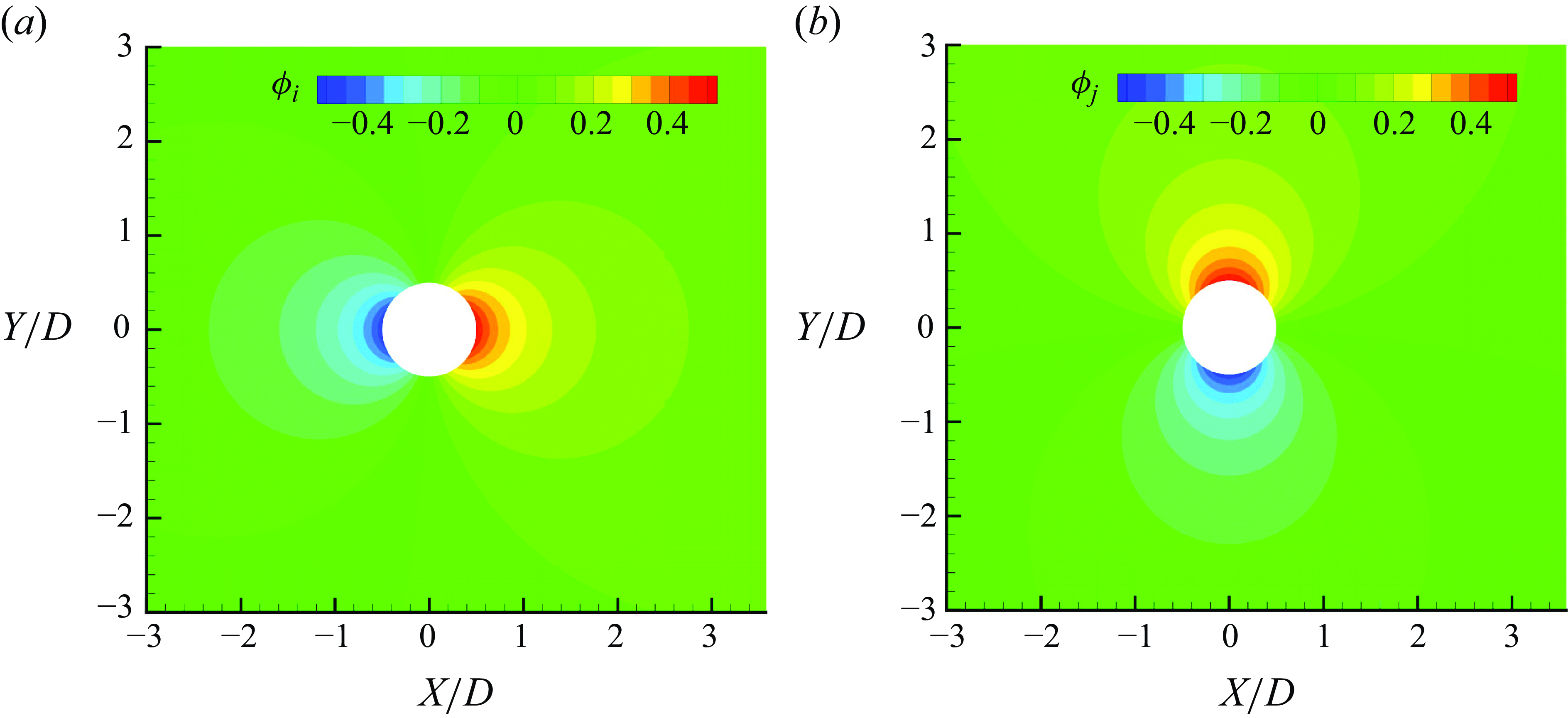
Auxiliary potentials (a)
 $\phi _i$
and (b)
 $\phi _j$
around the circular cylinder.

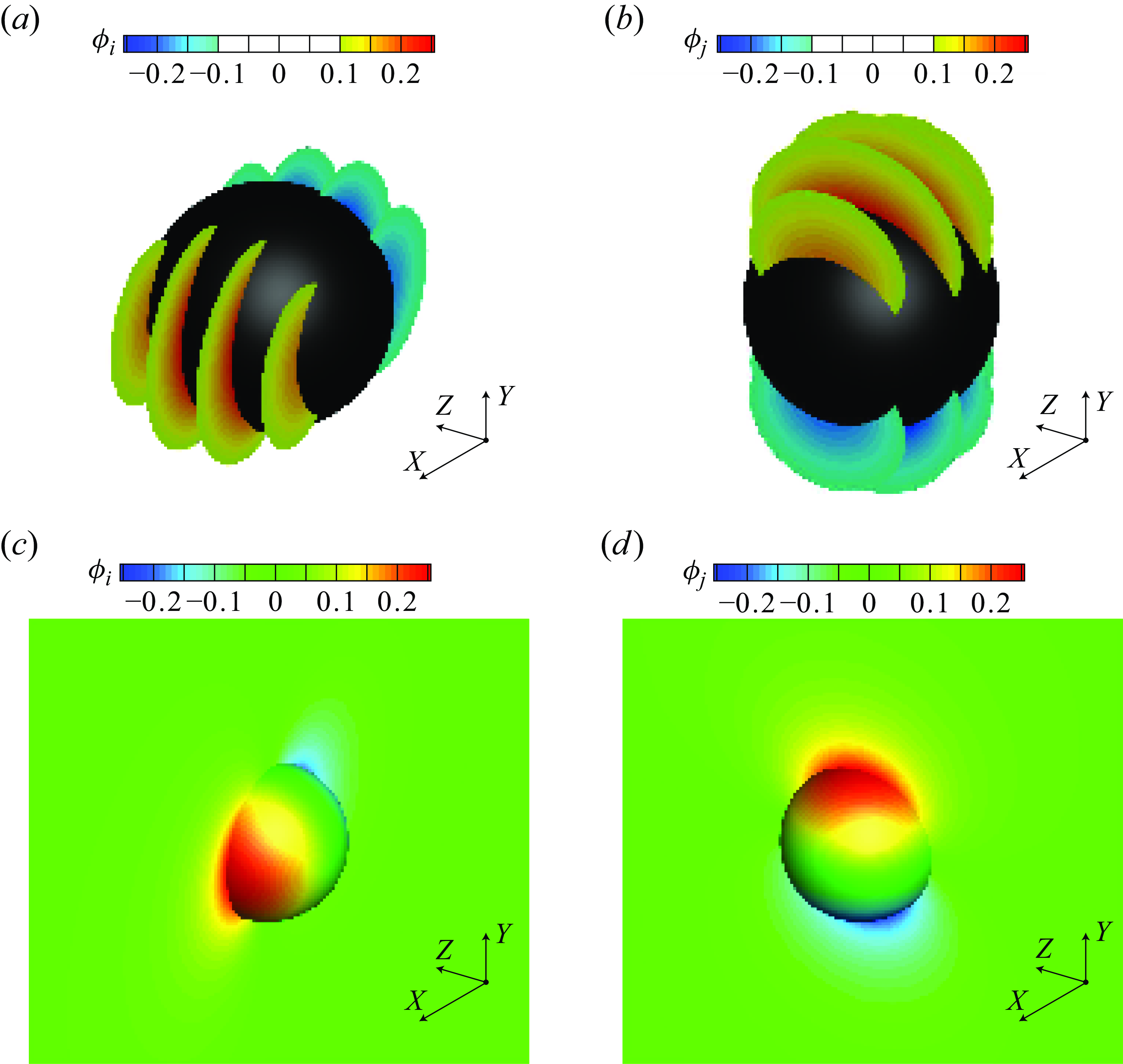
Auxiliary potentials (a,c)
 $\phi _i$
and (b,d)
 $\phi _j$
around the sphere. The distributions of auxiliary potentials (a)
 $\phi _i$
and (b)
 $\phi _j$
are shown on slices at
 $z = -0.6, -0.2$
, 0.2 and 0.6. The distributions of auxiliary potentials (c)
 $\phi _i$
and (d)
 $\phi _j$
are shown in the plane
 $z = 0$
and on the surface of the semi-sphere for
 $z \leqslant 0$
.

Figures 2(a) and 3(a,c) show a detailed view of
 $\phi _{i}$
around the circular cylinder and the sphere used in the present study, respectively. The advective and viscous terms in (2.1) are rewritten using the two vector identities below:
 \begin{equation} \boldsymbol {u}\cdot \nabla \boldsymbol {u}=\frac {1}{2}\nabla |\boldsymbol {u}|^{2}-\boldsymbol {u}\times \boldsymbol {\omega }, \end{equation}
 \begin{equation} \nabla ^{2}\boldsymbol {u}=\nabla (\nabla \cdot \boldsymbol {u})-\nabla \times \boldsymbol {\omega }=-\nabla \times \boldsymbol {\omega }, \end{equation}
and the corresponding momentum equation is written as
 \begin{equation} -\nabla p =\frac {\partial \boldsymbol {u}}{\partial t}+\frac {1}{2}\nabla |\boldsymbol {u}|^2-\boldsymbol {u}\times \boldsymbol {\omega }+\frac {1}{Re}(\nabla \times \boldsymbol {\omega }). \end{equation}
Taking the inner product with
 $\nabla \phi _i$
on both sides of (2.13) within the control volume
 $V_R$
(see figure 1), by making use of (2.2) and applying the Gauss divergence theorem, we derive
 \begin{eqnarray} \int _{S_{0}}p(\boldsymbol {n}\cdot \boldsymbol {i})\mathrm {\,d}A & = & \int _{S_{0}}\phi _{i}\frac {\partial \boldsymbol {u}}{\partial t}\cdot \boldsymbol {n}\mathrm {\,d}A -\frac {1}{2}\int _{S_{0}}|\boldsymbol {u}|^{2}\boldsymbol {n}\cdot \boldsymbol {i}\mathrm {\,d}A \nonumber \\ && - \int _{V_{R}}\boldsymbol {u}\times \boldsymbol {\omega } \cdot \nabla \phi _{i}\mathrm {\,d}V+\frac 1{Re}\int _{S_0} \boldsymbol {n}\times \boldsymbol {\omega }\cdot \nabla \phi _i\mathrm {\,d}A. \end{eqnarray}
Note that since
 $\nabla \phi _i=0$
and
 $\phi _{i}=0$
at
 $R \rightarrow \infty$
, the far-field terms
 $\int _{S_{R}}p(\boldsymbol {n}\cdot \boldsymbol {i})\mathrm {\,d}A$
,
 $\int _{S_{R}}\phi _{i}({\partial \boldsymbol {u}}/{\partial t})\cdot \boldsymbol {n}\mathrm {\,d}A$
,
 $-({1}/{2})\int _{S_{R}}|\boldsymbol {u}|^{2}\boldsymbol {n}\cdot \boldsymbol {i}\mathrm {\,d}A$
and
 $ ({1}/{Re})\int _{S_R} \boldsymbol {n}\times \boldsymbol {\omega }\cdot \nabla \phi _i\mathrm {\,d}A$
in (2.14) are equal to 0. Since we investigate flow over a rotating circular cylinder or a rotating sphere at a constant rotational speed, the first term
 $\int _{S_{0}}\phi _{i} ({\partial \boldsymbol {u}}/{\partial t})\cdot \boldsymbol {n}\mathrm {\,d}A$
on the right-hand side of (2.14) is 0. Equation (2.14) displays that the pressure force, which is the first term on the right-hand side of (2.5), is now expressed as a combined set of terms using information from the flow field. Substitute (2.14) into (2.5) and rewrite the drag coefficient
 $C_{D}$
. For the same reason that explains (2.5), we can express the drag coefficient as follows:
 \begin{eqnarray} \gamma C_{D} =-\frac {1}{2}\int _{S_{0}}|\boldsymbol {u}|^{2}\boldsymbol {n}\cdot \boldsymbol {i}\mathrm {\,d}A - \int _{V_{R}}\boldsymbol {u}\times \boldsymbol {\omega } \cdot \nabla \phi _{i}\mathrm {\,d}V+\frac {1}{Re}\int _{S_0} \boldsymbol {n}\times \boldsymbol {\omega }\cdot (\nabla \phi _i+\boldsymbol {i})\mathrm {\,d}A,\,\,\, \nonumber\\ \end{eqnarray}
where
 $\gamma =0.5$
for the circular cylinder and
 $\gamma =\pi /8$
for the sphere.
Based on the terminology used by Chang (Reference Chang1992),
 $- ({1}/{\gamma }){\boldsymbol {u}\times \boldsymbol {\omega } \cdot \nabla \phi _{i}}$
is the volume drag element,
 $({1}/{\gamma Re}){\boldsymbol {n}\times \boldsymbol {\omega }\cdot (\nabla \phi _i+\boldsymbol {i})}$
is the surface drag element and
 $-({1}/{2 \gamma }){|\boldsymbol {u}|^{2}\boldsymbol {n}\cdot \boldsymbol {i}}$
is the velocity drag element; all contributing to the drag. In combination with (2.15), the general drag coefficient
 $C_{D}$
in (2.5) can be abbreviated as
 \begin{eqnarray} C_{D} = C_{DM}+C_{DV}+C_{DS}. \end{eqnarray}
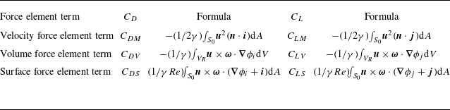
The velocity drag element term
 $-({1}/{2 \gamma }) \int _{S_{0}}|\boldsymbol {u}|^{2}\boldsymbol {n}\cdot \boldsymbol {i}\mathrm {\,d}A$
is the potential force associated only with the body motion, abbreviated as
 $C_{DM}$
. The volume drag element term
 $-({1}/{\gamma })\int _{V_{R}}\boldsymbol {u}\times \boldsymbol {\omega } \cdot \nabla \phi _{i}\mathrm {\,d}V$
represents the contribution of the pressure force due to the vorticity within the flow field, abbreviated as
 $C_{DV}$
. The surface drag element term
 $ ({1}/{\gamma Re})\int _{S_0} \boldsymbol {n}\times \boldsymbol {\omega }\cdot (\nabla \phi _i+\boldsymbol {i})\mathrm {\,d}A$
represents the contribution of the vorticity on the body surface, abbreviated as
 $C_{DS}$
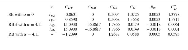
. The more detailed decomposition terms of the drag coefficient
 $C_{D}$
by FEA are shown in table 1.


However, one can introduce an auxiliary potential function
 $\phi _j$
that satisfies the Laplace equation
 \begin{equation} \nabla ^{2}\phi _{j}=0 \end{equation}
and boundary conditions:
 \begin{equation} \nabla \phi _{j}\cdot \boldsymbol {n}=-\boldsymbol {j}\cdot \boldsymbol {n}, \quad \boldsymbol {r} \; \mbox {on} \; S_{0}, \end{equation}
 \begin{equation} \phi _{j}=0,\quad \boldsymbol {r} \rightarrow \infty . \end{equation}
Figures 2(b) and 3(b,d) show a detailed view of
 $\phi _{j}$
around the circular cylinder and the sphere used in the present study, respectively. Likewise, we may express the lift coefficient as follows:
 \begin{eqnarray} \gamma C_{L} =-\frac {1}{2}\int _{S_{0}}|\boldsymbol {u}|^{2}\boldsymbol {n}\cdot \boldsymbol {j}\mathrm {\,d}A -\int _{V_{R}}\boldsymbol {u}\times \boldsymbol {\omega } \cdot \nabla \phi _{j}\mathrm {\,d}V+\frac {1}{Re}\int _{S_0} \boldsymbol {n}\times \boldsymbol {\omega }\cdot (\nabla \phi _j+\boldsymbol {j})\mathrm {\,d}A,\,\,\,\,\,\, \nonumber\\ \end{eqnarray}
where
 $\gamma =0.5$
for the circular cylinder and
 $\gamma =\pi /8$
for the sphere.
In combination with (2.20), the general lift coefficient
 $C_{L}$
in (2.6) can be abbreviated as
 \begin{eqnarray} C_{L} = C_{LM}+C_{LV}+C_{LS}, \end{eqnarray}
where
 $-({1}/{\gamma })\boldsymbol {u}\times \boldsymbol {\omega } \cdot \nabla \phi _{j}$
is the volume lift element,
 $ ({1}/{\gamma Re})\boldsymbol {n}\times \boldsymbol {\omega }\cdot (\nabla \phi _j+\boldsymbol {j})$
is the surface lift element and
 $- ({1}/{2 \gamma })|\boldsymbol {u}|^{2}\boldsymbol {n}\cdot \boldsymbol {j}$
is the velocity lift element; all contributing to the lift. The more detailed decomposition terms of the lift coefficient
 $C_{L}$
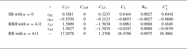
by FEA are listed in table 1.
For flow past a rotating circular cylinder, it is well known that the Magnus effect can significantly increase the lift coefficient while drastically reducing the drag coefficient, However, the purpose of this study is to significantly reduce the drag without substantially incurring the lift, i.e. ideally, to achieve minimum drag with little lift. According to the FEA, rotating the bluff body with a stationary hood over its rear half may significantly reduce the drag of the bluff body (circular cylinder or sphere), as the velocity drag element term
 $C_{DM}$
in (2.15) is negative. Yet, it is noted that the velocity lift element term
 $C_{LM}$
in (2.20) is zero.
The velocity drag element term
 $C_{DM}$
in (2.16) and its detailed expression in (2.15) can be decomposed into the sum of integrals over the front and rear surfaces of the bluff body, as follows:
 \begin{equation} \begin{aligned} C_{DM}=-\frac {1}{2 \gamma }\int _{S_0}\boldsymbol {u}^2(\boldsymbol {n}\cdot \boldsymbol {i})\mathrm {d}A=-\frac {1}{2 \gamma }\int _{S_{0f}}\boldsymbol {u}^2(\boldsymbol {n}\cdot \boldsymbol {i})\mathrm {d}A-\frac {1}{2 \gamma }\int _{S_{0b}}\boldsymbol {u}^2(\boldsymbol {n}\cdot \boldsymbol {i})\mathrm {d}A. \end{aligned} \end{equation}
Here,
 $S_{0f}$
and
 $S_{0b}$
represent the front and rear surfaces of the bluff body, respectively. Under RBH, a stationary hood is over the rear half of the rotating circular cylinder or the rotating sphere, causing the second term in the right-hand of the (2.22) to be equal to 0. In addition, the following formula:
 \begin{equation} \begin{aligned} \boldsymbol {n}\cdot \boldsymbol {i}\gt 0 \end{aligned} \end{equation}
holds on the surface
 $S_{0f}$
of the front half of the rotating circular cylinder or the rotating sphere. Combining (2.22) and (2.23) gives
 \begin{equation} \begin{aligned} C_{DM}=-\frac {1}{2 \gamma }\int _{S_0}\boldsymbol {u}^2(\boldsymbol {n}\cdot \boldsymbol {i})\mathrm {d}A\lt 0. \end{aligned} \end{equation}
However, there is another volume drag element term
 $C_{DV}$
and surface drag element term
 $C_{DS}$
, which may also change drastically, hence the net effect on drag reduction must be carefully examined.
In addition, the circular cylinder and the sphere are symmetric about the
 $x$
-axis and the
 $x$
–
 $z$
plane, respectively, thus the integral value of the velocity lift element term
 $C_{LM}$
in (2.21) is zero,
 \begin{equation} \begin{aligned} C_{LM}=-\frac {1}{2 \gamma }\int _{S_0}\boldsymbol {u}^2(\boldsymbol {n}\cdot \boldsymbol {j})\mathrm {d}A=0. \end{aligned} \end{equation}
2.2. Physical problem and numerial validation
In this section, we will first describe the physical problem and the numerical method (software), and then proceed with the validation of the numerical results with checks against the grid resolution and comparisons with previous results published in the literature.
Figure 1 is a schematic of the physical problem of flow (with an incoming velocity
 $U_\infty$
) past a rotating circular cylinder of diameter
 $D$
or a rotating sphere of diameter
 $D$
using the drag reduction method RBH. Let
 $(x^*,y^*) = (0,0)$
and
 $(x^*,y^*,z^*) = (0,0,0)$
be the centre location of the circular cylinder and the sphere, respectively. The domain of computation for the flow over a circular cylinder used is
 $-20D \leqslant x^* \leqslant 40D$
and
 $-20D \leqslant y^* \leqslant 20D$
. The cylinder surface satisfies the no-slip condition, and the upper and lower plates (at
 $y^* = \pm 20D$
) also satisfy the far-field condition, while the exit downstream (
 $x^* = 40D$
) satisfies the pressure outlet condition. The cylindrical domain of computation for the flow over a sphere is of radius 15 times that of the sphere’s diameter and height 45 times that of the sphere’s diameter. The inlet and the outlet of the numerical domain are at the distances 15 times that of the sphere’s diameter and 30 times that of the sphere’s diameter from the centre of the sphere, respectively.
The solver software and numerical schemes used are as follows. This paper employs the commercial software FLUENT 2022, using the finite volume method to solve the Navier–Stokes equations. This study examines incompressible flow around blunt bodies at low Reynolds numbers. Consequently, a pressure-based solver and a laminar flow model are the appropriate choices. To enhance the stability and convergence of the solution, we employ the SIMPLEC scheme and the Rhie–Chow distance-based flux type in the pressure–velocity coupling algorithm. To accurately capture the vortex shedding transient phenomenon, we select the second-order implicit from the transient formulation. To achieve higher accuracy, the least squares method is employed to calculate the gradient in spatial discretisation. The pressure term is discretised using second-order interpolation, while the convection and diffusion terms in the momentum equation are discretised with a second-order upwind scheme.
To obtain a more accurate representation of the flow field changes around the blunt body, we not only refine the mesh around the blunt body, but also reduce the mesh size on the surface and within the boundary layer. The mesh size at the surface of the blunt body is set to 0.02
 $D$
, the height of the first layer in the boundary layer is set to 0.01
 $D$
, the growth rate of the mesh is set to 1.1 and the total number of layers is 25.
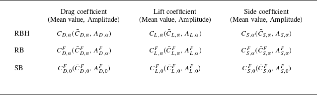
For the oscillating force coefficients, we define the mean value and the amplitude of oscillation for both RB and the drag reduction method RBH, as listed in table 2. The amplitude
 $A_{D}$
of the oscillation of the drag coefficient
 $C_D$
,
 \begin{equation} \begin{aligned} A_{D}=\frac {|C_{Dmax}-C_{Dmin}|}{2}, \end{aligned} \end{equation}
and the amplitude
 $A_{L}$
of the oscillation of the lift coefficient
 $C_L$
,
 \begin{equation} \begin{aligned} A_{L}=\frac {|C_{Lmax}-C_{Lmin}|}{2}, \end{aligned} \end{equation}
are defined. Here,
 $C_{Dmax}$
and
 $C_{Dmin}$
denote the maximum and minimum of the drag coefficient
 $C_D$
, respectively;
 $C_{Lmax}$
and
 $C_{Lmin}$
denote the maximum and minimum of the lift coefficient
 $C_L$
, respectively. To measure the effectiveness of drag reduction method RBH and compare it to RB, three ratios are defined: the drag reduction ratio
 $\eta _1 = {\bar {C}_{D,\alpha }}/{\bar {C}_{D,0}^F}$
and the lift amplitude ratio
 $\eta _2 = {A_{L,\alpha }}/{A_{L,0}^F}$
associated with RBH, and the mean lift ratio
 $\eta _3 = {\bar {C}_{L,\alpha }}/{\bar {C}_{L,\alpha }^F}$
associated with RB and RBH.
Abbreviation for the mean value and amplitude of force coefficients under RBH, RB and SB. The subscript,
 $\alpha$
, denotes the quantity is obtained under the condition of rotating the body with the speed
 $\alpha$
. The superscript,
 $F$
, denotes the rotating body fully exposed to the fluid, and without an
 $F$
, it means that there is a hood over the rear surface.

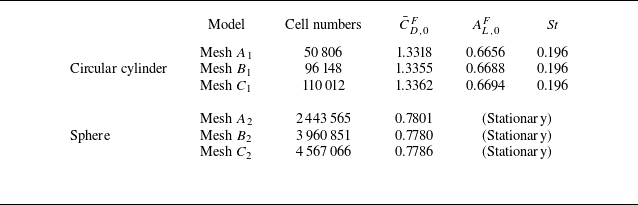
Next, the independence of grid and time step is determined. The grid independence has been checked against three meshes
 $A_i$
,
 $B_i$
and
 $C_i$
(table 3, from the coarser to the finer;
 $i$
= 1, 2 represent the stationary circular cylinder in two dimensions and the stationary sphere, respectively) for computing the force coefficients and Strouhal number. At the time step
 $\delta t$
= 0.005, the calculated results of the finer meshes
 $B_i$
and
 $C_i$
still show some little differences in the force coefficients, but are well within those values published in the literature. Mesh
 $B_i$
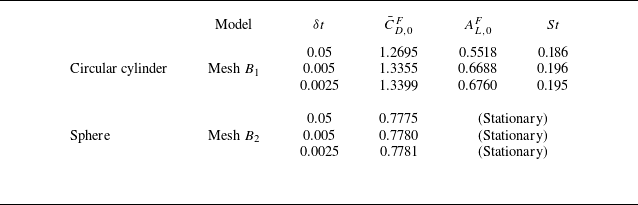
is considered to be acceptable. In table 4, we have also checked the time step independence with
 $\delta t$
= 0.05, 0.005 and 0.0025 with using mesh
 $B_i$
, and have observed smaller variations between the results of
 $\delta t$
= 0.005 and 0.0025, indicating that it is appropriate to employ mesh
 $B_i$
and the time step
 $\delta t$
= 0.005 throughout the study.
Verification of the independence of the grid for the flow over a stationary circular cylinder or a stationary sphere in the unbounded fluid with the dimensionless time step
 $ \delta t$
= 0.005 at
 $Re$
= 200.
 $\bar {C}_{D,0}^F$
and
 $A_{L,0}^F$
are the mean drag coefficient and the amplitude of the lift coefficient fluctuations, respectively.
 $St$
is the Strouhal number, which is related to the vortex shedding frequency.

Verification of the independence of the time step for the flow over a stationary circular cylinder or a stationary sphere with mesh
 $B_i$
in table 3 at
 $Re$
= 200.

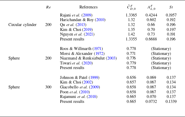
Finally, we verify the numerical results by comparing the mean drag coefficient
 $\bar {C}_{D,0}^F$
, the amplitude
 $A_{L,0}^F$
of the lift coefficient fluctuations and the vortex shedding frequency
 $f_{VS}$
with some known values published previously. The Strouhal number
 $St$
is often used to represent the non-dimensional vortex shedding frequency
 $St = f_{VS}$
. Comparing the mean drag coefficient
 $\bar {C}_{D,0}^F$
, the amplitude
 $A_{L,0}^F$
and Strouhal number
 $St$
with those taken from several known references, the presently calculated results is reasonable, as listed in table 5.
Force coefficients and Strouhal number of the stationary circular cylinder at
 $Re$
= 200 or the stationary sphere at
 $Re$
= 200 and at
 $Re = 300$
with mesh
 $B_i$
in table 3 and the dimensionless time step
 $ \delta t$
= 0.005.

3. Results and discussion
In this section, numerical simulations of flow past a bluff body at low Reynolds numbers are conducted, including flow past a circular cylinder or a sphere with comparisons of RB and RBH results. The evolution of the force coefficients is presented. The velocity force element term, volume force element term and surface force element term of the force coefficients are obtained using FEA, and the reasons for the drag and lift reduction achieved by RBH are analysed in detail. The cases of flow past a circular cylinder at
 $Re$
= 200 is presented in § 3.1 and flow past a sphere at
 $Re$
= 200 and
 $Re$
= 300 are presented in § 3.2.
3.1.
Simultaneous reduction of drag and lift for the circular cylinder at
 $Re$
= 200

This section analyses the behaviours of RB (Magnus effect) and RBH for drag reduction in the range of
 $0 \leqslant \alpha \leqslant 5$
at
 $Re$
= 200. The drag reduction method RBH significantly reduces drag while maintaining a small amount of lift. The detailed FEA shows that although the rotation of the circular cylinder increases the volume force element term in the force coefficients, the strongly negative velocity drag element term
 $C_{DM}$
counteracts the strongly increased volume drag element term
 $C_{DV}$
and the increased surface drag element term
 $C_{DS}$
for the drag coefficient; the decrease in the surface lift element term
 $C_{LS}$
counteracts the increased volume lift element term
 $C_{LV}$
for the lift coefficient.
3.1.1. Force coefficients of the circular cylinder at different rotation speed
In this section, we will discuss the characteristics (mean value, amplitude, frequency, phase diagram, etc.) of the force coefficients of the circular cylinder at different rotational speeds to demonstrate the advantages of exploiting drag reduction method RBH. We also present the shift of the surface separation points of the circular cylinder at different rotational speeds and its connection with variations of the force coefficients.
(Circular cylinder) Force coefficients and three ratios with respect to different rotating speed
 $\alpha$
at
 $Re = 200$
. (a) Force coefficients using RBH. (b,c) Force coefficients using RB. (d) Three ratios measuring the effectiveness of drag reduction. The error bars indicate the amplitude
 $A_{D}$
of oscillation in the drag coefficient
 $C_D$
or the amplitude
 $A_{L}$
of oscillation in the lift coefficient
 $C_L$
.

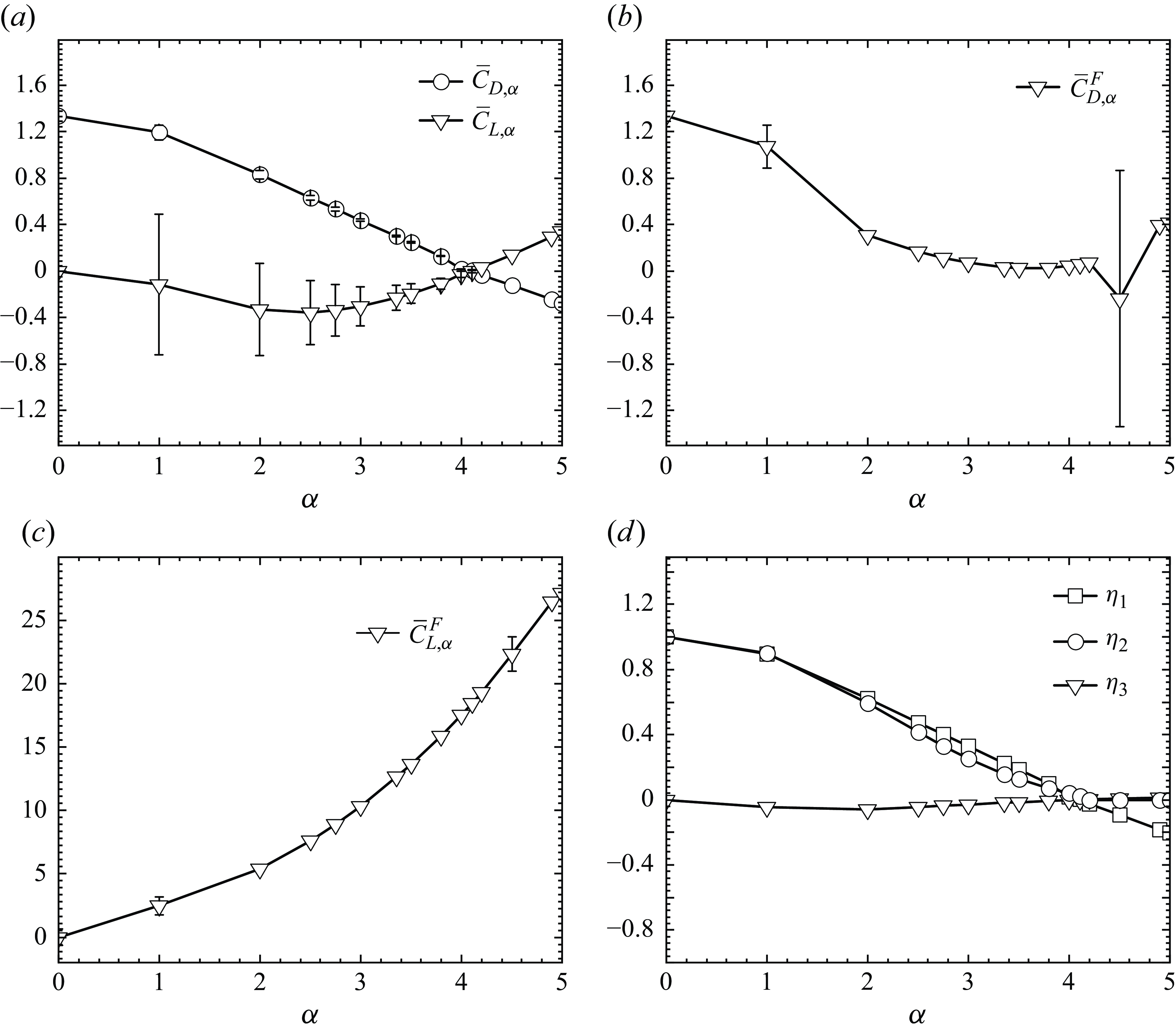
Figure 4 depicts the evolution of the force coefficient of the circular cylinder and three ratios measuring the effectiveness of RBH with respect to
 $\alpha$
. Three important conclusions can be drawn from figure 4.
-
(i) Under RBH, as
$\alpha$
increases from 0 to 5, the mean drag coefficient
$\bar {C}_{D,\alpha }$
decreases monotonically from 1.3355 to −0.2741; the mean lift coefficient
$\bar {C}_{L,\alpha }$
decreases monotonically from 0 to −0.3544 (
$\alpha$
= 2.5), then monotonically increases to 0.3402; in addition, the amplitude of the force coefficients gradually decreases to 0 (
$\alpha$
= 4.2) and the flow field gradually becomes steady, as shown in figure 4(a). -
(ii) Under RB, as
$\alpha$
increases from 0 to 5, the mean drag coefficient
$\bar {C}_{D,\alpha }^F$
decreases monotonically from 1.3355 to 0.0266 (
$\alpha =3.5$
) and then increases monotonically to 0.4154, as shown in figure 4(b); the mean lift coefficient
$\bar {C}_{F,\alpha }^F$
increases monotonically sharply to 27.1415, as shown in figure 4(c); similar to conclusion (i), the amplitude of the force coefficients also diminishes to zero and the flow field also remains steady, except for individual intervals
$4.34 \leqslant \alpha \leqslant 4.7$
(Cheng, Liu & Lam 2001) of the rotational speed cases. Specifically, the flow field changes drastically and the amplitude of the force coefficients becomes very large at
$\alpha$
= 4.5. This phenomenon is known as the vortex shedding mode II and is discussed in the related literature (Cheng, Liu & Lam 2001). -
(iii) Under RBH, as the speed increases from 0 to 5, the drag reduction ratio
$\eta _1$
and the lift amplitude ratio
$\eta _2$
of the lift amplitude decrease, indicating a progressive reduction in the average drag coefficient and the lift coefficient amplitudes. In addition, the mean lift ratio
$\eta _3$
is within
$\pm 0.07$
, indicating that the mean lift coefficient obtained using RBH is significantly less than that obtained using the method RB, as shown in figure 4(d). -
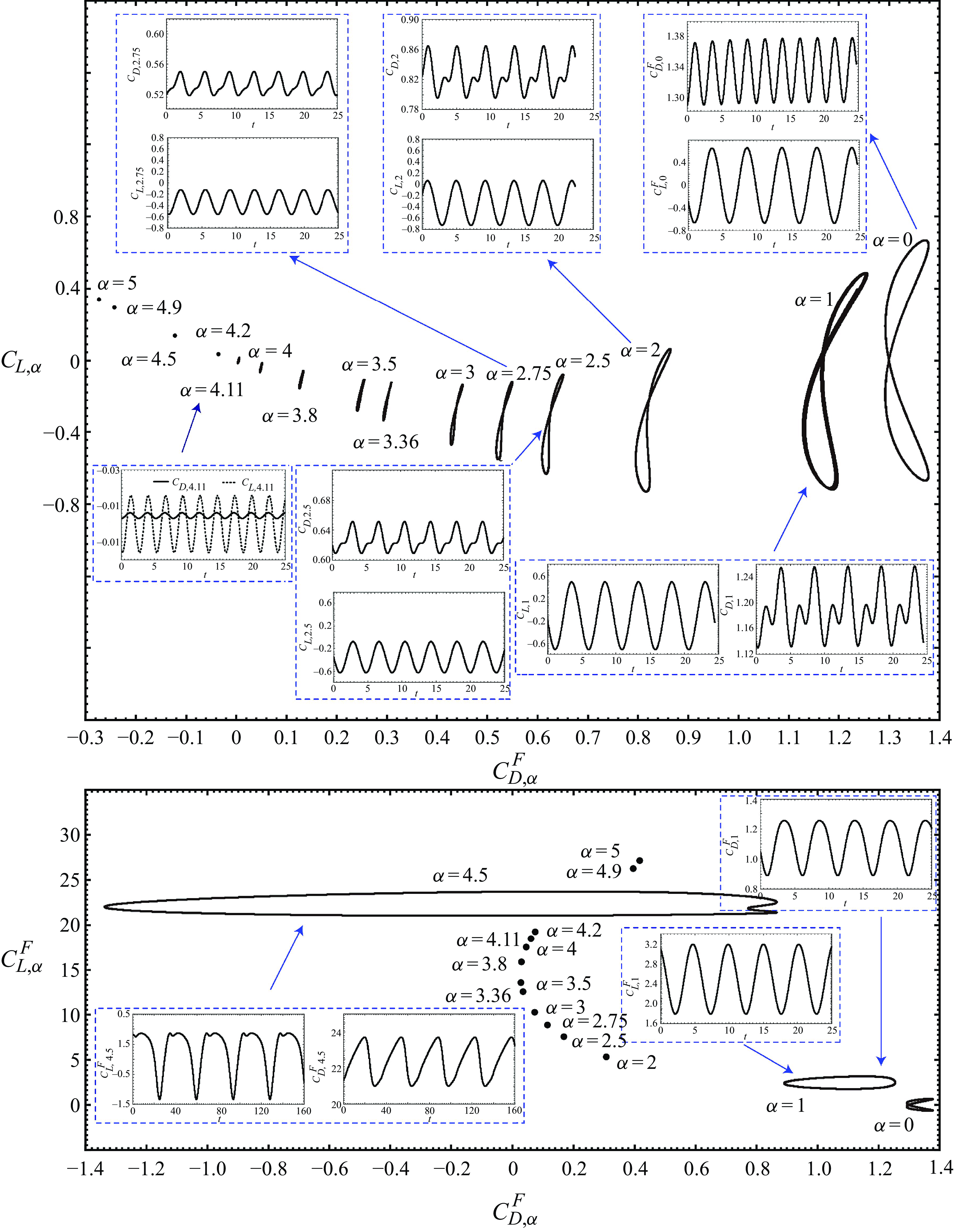
(iv) In the phase diagram of the drag coefficient and the lift coefficient, when
$\alpha =0$
, the diagram shows a relatively full, upper and lower symmetrical 8-figure shape, as shown on the far right of figure 5(a). This is because both coefficients exhibit oscillations of equal amplitude, resembling cosine functions, as illustrated in the time evolution diagram within the blue dashed box in the upper right-hand corner of figure 5(a). At
$\alpha =1$
, the phase diagram becomes shorter and narrower, losing its upper and lower symmetry, since the time evolution of the drag coefficient no longer exhibits oscillations of equal amplitude, resembling trigonometric functions. For details, refer to the time evolution diagram of the drag coefficient in the blue dashed box in the lower right-hand corner of figure 5(a). As
$\alpha$
increases to 4.11, the phase diagram further shortens and narrows, while the flow field remains unsteady and relatively complex. As
$\alpha$
reaches or exceeds 4.2, the phase diagram formed by the lift coefficient and drag coefficient collapses to a point, mainly because both coefficients become constant, indicating a steady flow field. -
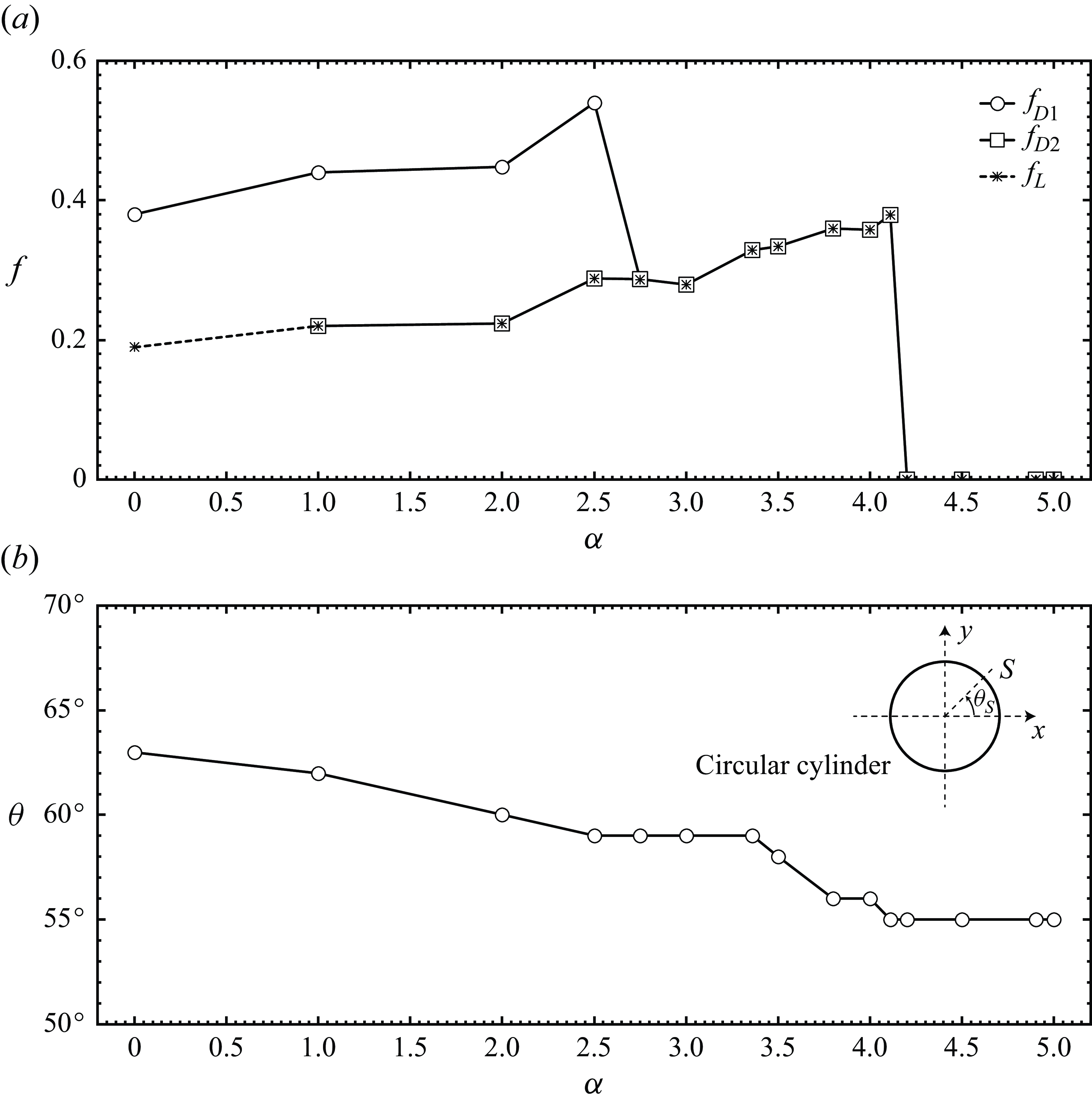
(v) In figure 6(a), as
$\alpha$
increases from 0 to 4.11, the frequency of the lift coefficient (i.e. the vortex shedding frequency) gradually increases using RBH. As
$\alpha$
reaches or exceeds 4.2, the vortex shedding is completely suppressed, resulting in constant values for both the drag coefficient and the lift coefficient. When the circular cylinder is stationary (i.e. when
$\alpha =0$
), the vortex in the wake alternately detaches from the circular cylinder, with the drag coefficient having a single frequency
$f_{D1}$
and the lift coefficient exhibiting a single frequency
$f_L$
, satisfying the relationship
$f_{D1}=2f_L$
. As
$\alpha$
increases from 1 to 2.5, the drag coefficient includes two frequencies
$f_{D1}$
and
$f_{D2}$
, satisfying
$f_{D1}=2f_{D2}$
. As
$\alpha$
increases from 2.75 to 4.11, both the drag coefficient and lift coefficient contain a single frequency
$f_{D1}$
and
$f_L$
, satisfying
$f_{D1}=f_L$
. -
(vi) It is also of interest to observe how the point of separation shifts as
$\alpha$
increases. Here, the separation is defined as occurring at the location (point) on the surface where
$\boldsymbol {\omega } = 0$
, from which a line of separation emerges. As
$\alpha$
gradually increases from 0 to 5, the position of the separation point on the surface of the circular cylinder shifts from
$63^{\circ }$
to
$55^{\circ }$
, as shown in figure 6(b). Shift of the separation point
$S$
towards downstream with increasing
$\alpha$
is accompanied with reduction in the mean value of
$C_D$
and its oscillation
$A_D$
as well as in the lift oscillation
$A_L$
. This is reasonable as the narrower wake indicates a smaller or less violent contribution of the volume vorticity (
$C_{DV}$
and
$C_{LV}$
) to the force coefficients.


Considering both drag and lift coefficients, RBH has greater advantages. As mentioned in the items above, RBH is adopted to achieve significant drag reduction without generating too much lift and the flow gradually becomes steady.
(Circular cylinder) Phase diagram and the time history of the lift coefficient and drag coefficient under (a) the drag reduction method RBH and (b) RB at various
 $\alpha$
with
 $Re = 200$
.

(Circular cylinder) Frequencies of the force coefficients and the separation point at different rotational speeds by using RBH with
 $Re = 200$
. (a) Frequencies (
 $f_{D1}, f_{D2}$
) of the drag coefficient and the frequency
 $f_L$
of the lift coefficient. (b) Position of the separation point
 $S$
on the surface of the circular cylinder and the corresponding angle
 $\theta _s$
.

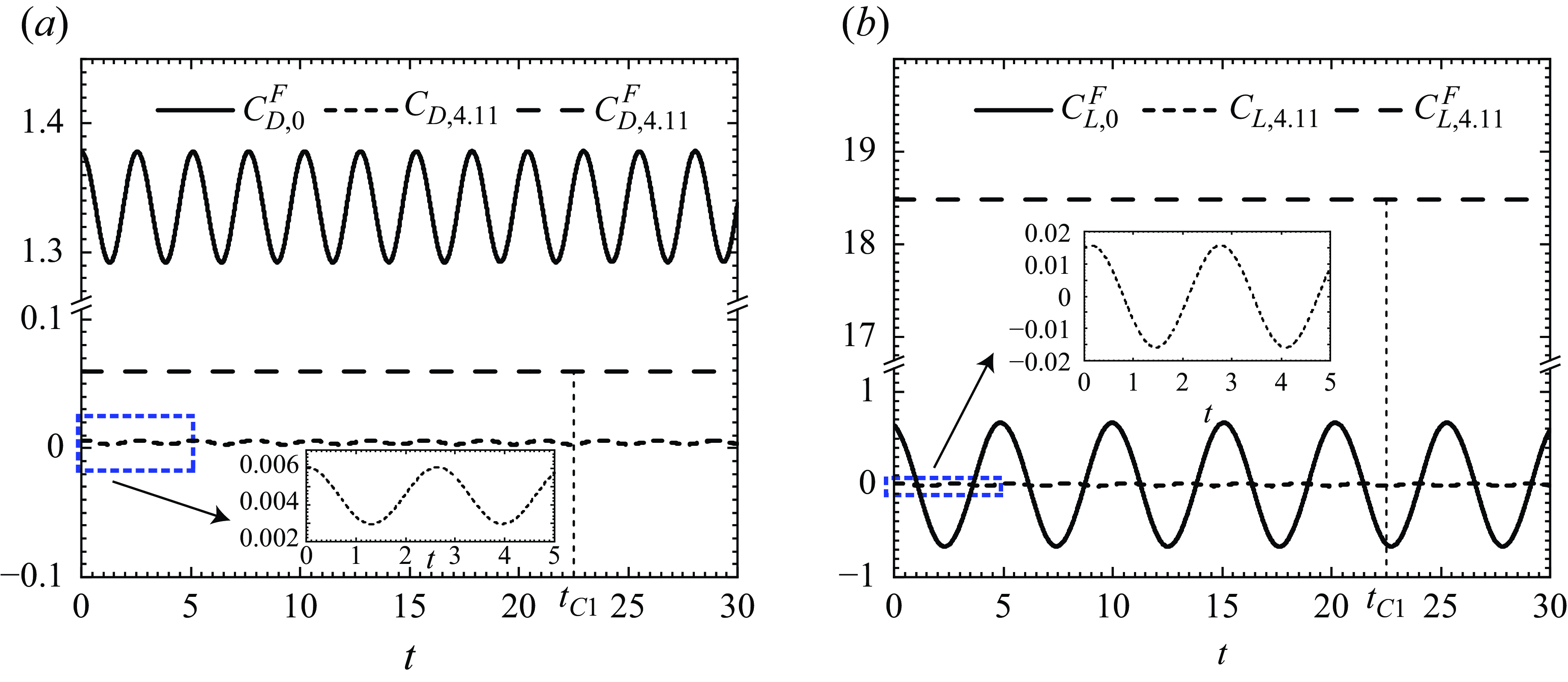
Under RBH, using the data in figure 4(a), we may locate an optimal
 $\alpha _I = 4.11$
, at which
 $\bar {C}_{L, \alpha }=0$
and
 $\bar {C}_{D, \alpha }=0.0045$
. This not only achieves a large reduction in drag, but also keeps the average lift coefficient at 0.
As
 $\alpha$
increases from 0 to 4.11, there are some conclusions in figure 7. Under RBH, the drag coefficient of the circular cylinder decreases from
 $C_{D,0}^F$
with mean value
 $\bar {C}_{D,0}^F=1.3355$
and amplitude
 $A_{D,0}^F=0.0431$
to
 $C_{D, 4.11}$
with small mean value
 $\bar {C}_{D,4.11}=0.0045$
and minimal amplitude
 $A_{D,4.11}=0.0016$
, as shown in figure 7(a); the drag coefficient, compared with that of a stationary circular cylinder, are reduced by 99.66
 $\%$
in the mean from 1.3355 to 0.0045; the lift coefficient of the circular cylinder decreases from
 $C_{L,0}^F$
with mean value
 $\bar {C}_{L,0}^F=0$
and large amplitude
 $A_{L,0}^F=0.6683$
to
 $C_{L,4.11}$
with mean value
 $\bar {C}_{L,4.11}=0$
and minimal amplitude
 $A_{L,4.11}=0.0158$
, as shown in figure 7(b); the amplitude of the lift coefficient, compared with that of a stationary circular cylinder, are reduced by 97.64
 $\%$
in the amplitude from 0.6683 to 0.0158.
(Circular cylinder) Under SB, RB and RBH with
 $Re = 200$
and
 $\alpha =4.11$
, the time history of (a) drag coefficient
 $C_D$
and (b) lift coefficient
 $C_L$
.

Under RB, the drag coefficient of the circular cylinder decreases from
 $C_{D,0}^F$
with mean value
 $\bar {C}_{D,0}^F=1.3355$
and amplitude
 $A_{D,0}^F=0.0431$
to
 $C_{D,\alpha }^F$
with small mean value
 $\bar {C}_{D,4.11}^F=0.0593$
, as shown in figure 7(a); the drag coefficient, compared with that of a stationary circular cylinder, are reduced by 95.56
 $\%$
in the mean from 1.3355 to 0.0593; the lift coefficient of the circular cylinder increases sharply from
 $C_{L,0}^F$
with mean value
 $\bar {C}_{L,0}^F=0$
and large amplitude
 $A_{L,0}^F=0.6683$
to
 $C_{L,4.11}^F$
with large mean value
 $\bar {C}_{L,4.11}^F=18.4861$
, as shown in figure 7(b). Although rotating the circular cylinder can reduce drag as much as rotating only the front half of the circular cylinder, the lift increases dramatically.
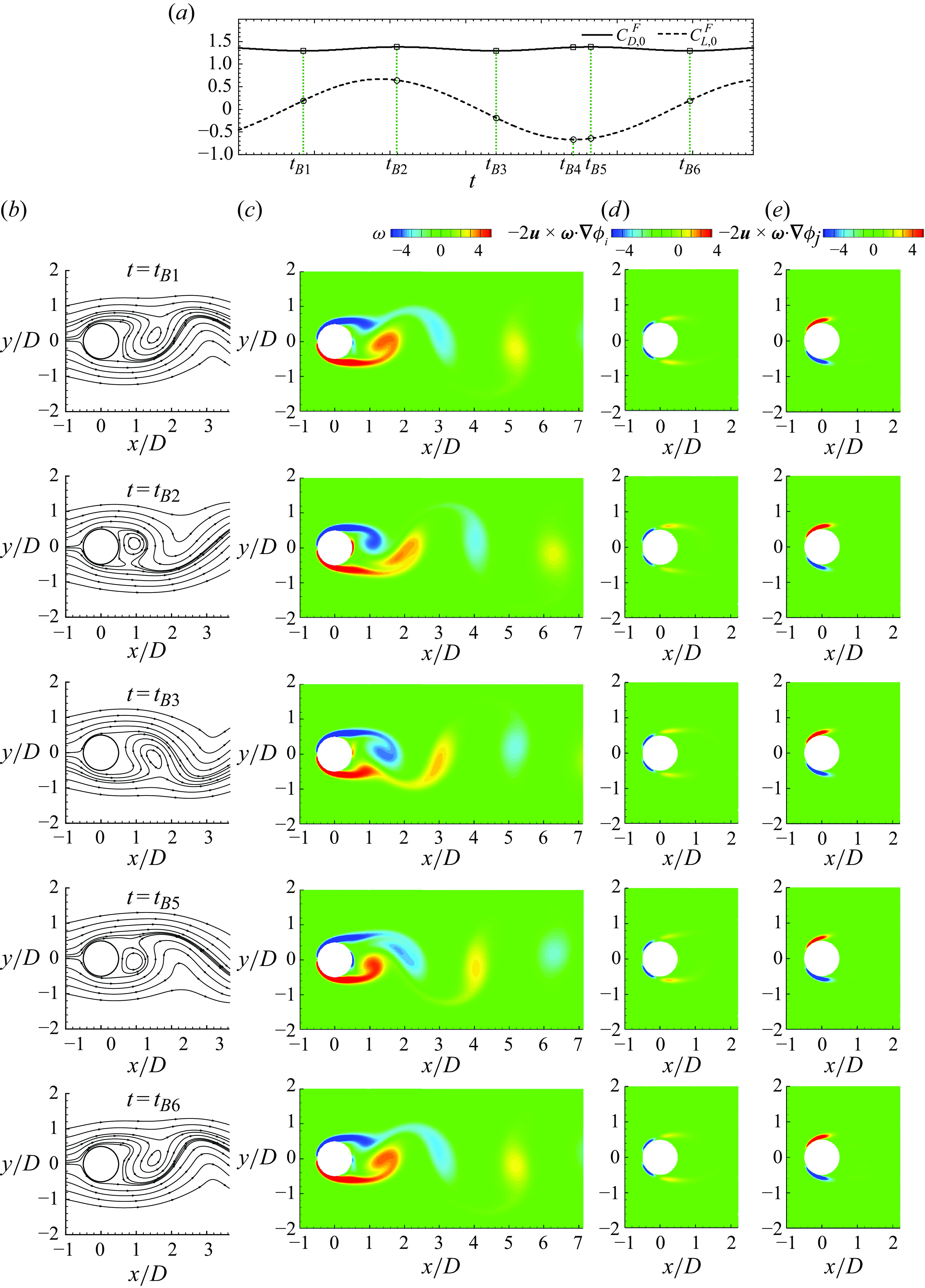
(Circular cylinder) Under SB with
 $Re = 200$
: (a) time history of force coefficients; the flow visualisation demonstrating (b) streamlines; (c) vorticity; (d) magnitude of the volume drag element
 $-2\boldsymbol {u}\times \boldsymbol {\omega }\cdot \boldsymbol {\nabla }\phi _{i}$
in (2.15) for the drag coefficient; and (e) the magnitude of the volume lift element
 $-2\boldsymbol {u}\times \boldsymbol {\omega }\cdot \boldsymbol {\nabla }\phi _{j}$
in (2.20) for the lift coefficient.

As mentioned above, using the optimal rotation speed
 $\alpha _I=4.11$
, the advantages of RBH are thoroughly analysed. Considering both the drag and lift reduction, RBH demonstrates greater advantages.
3.1.2. Analysing lift and drag of the circular cylinder by force element theory
Vortex plays an important role in flow field analysis. Vortex generation, shedding and migration are closely related to the forces exerted on a circular cylinder. As indicated by (2.15) and (2.20), the FEA decomposes the force of the circular cylinder into the volume vorticity force term, the surface vorticity force term and the velocity force term. Among these, the volume vorticity force term reflects the influence of vorticity in the flow field on the force. This section first examines the changes in vorticity and streamlines around the circular cylinder as
 $\alpha$
increases under RBH, and then applies the FEA to investigate the mechanisms behind the drag and lift reduction.
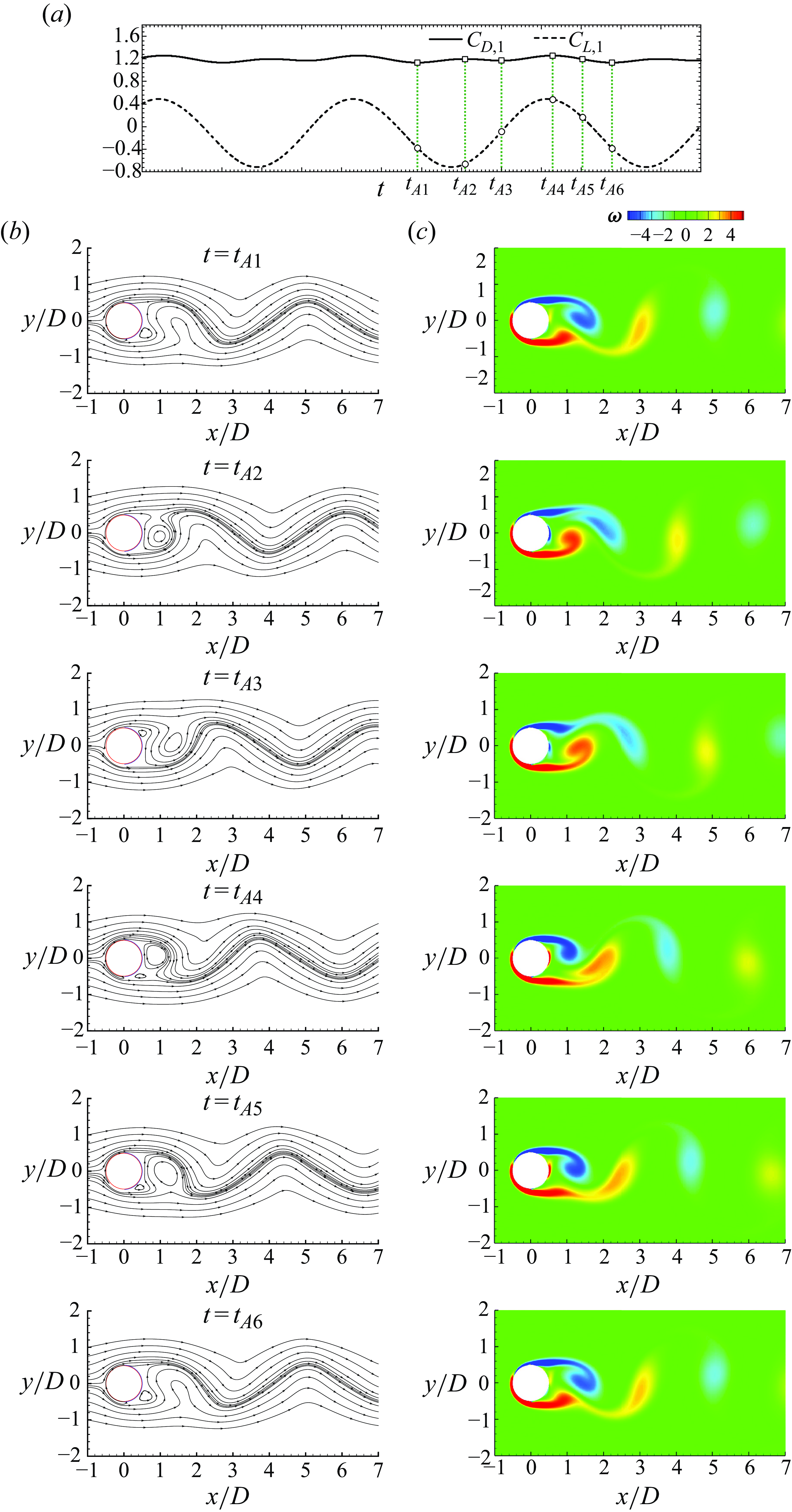
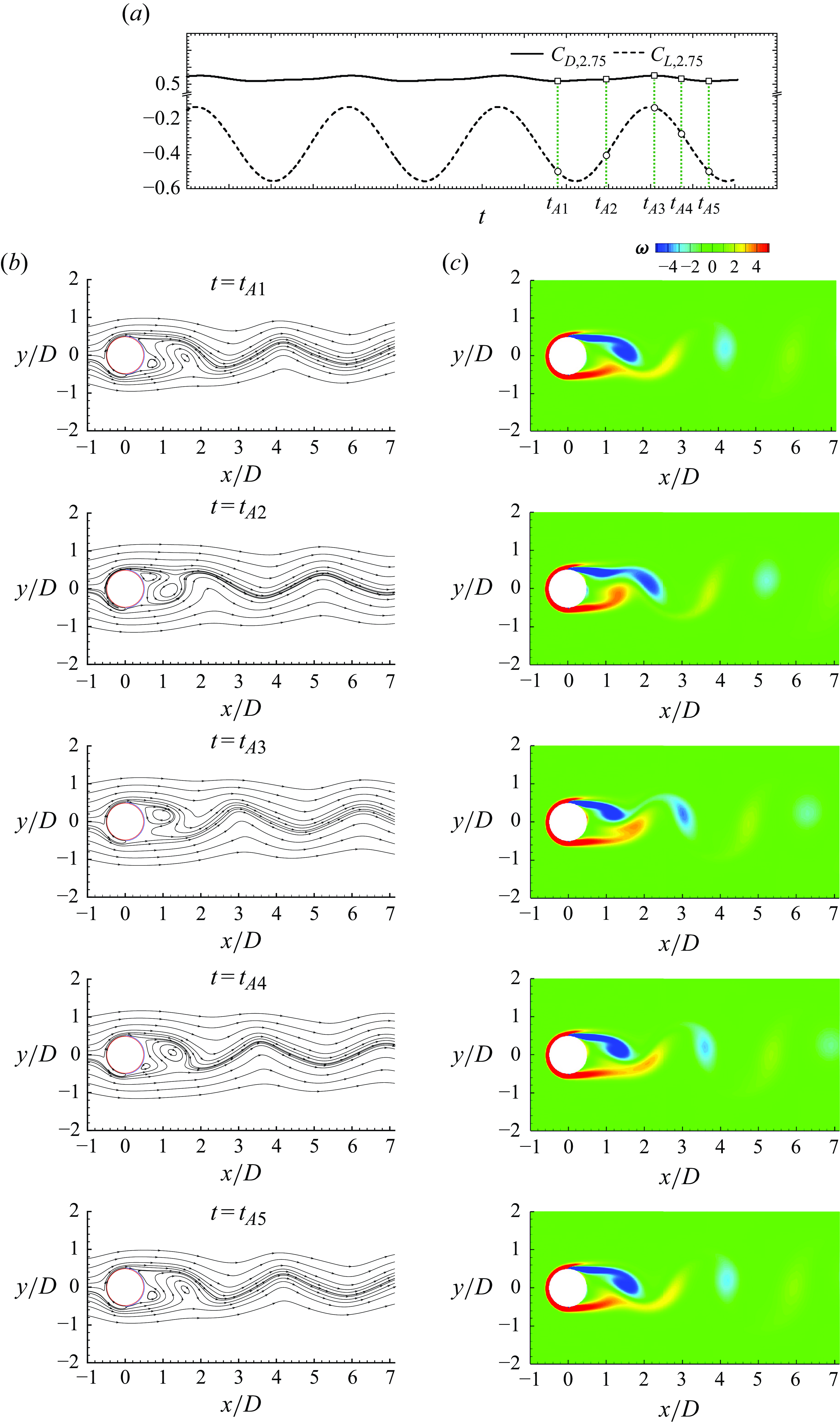
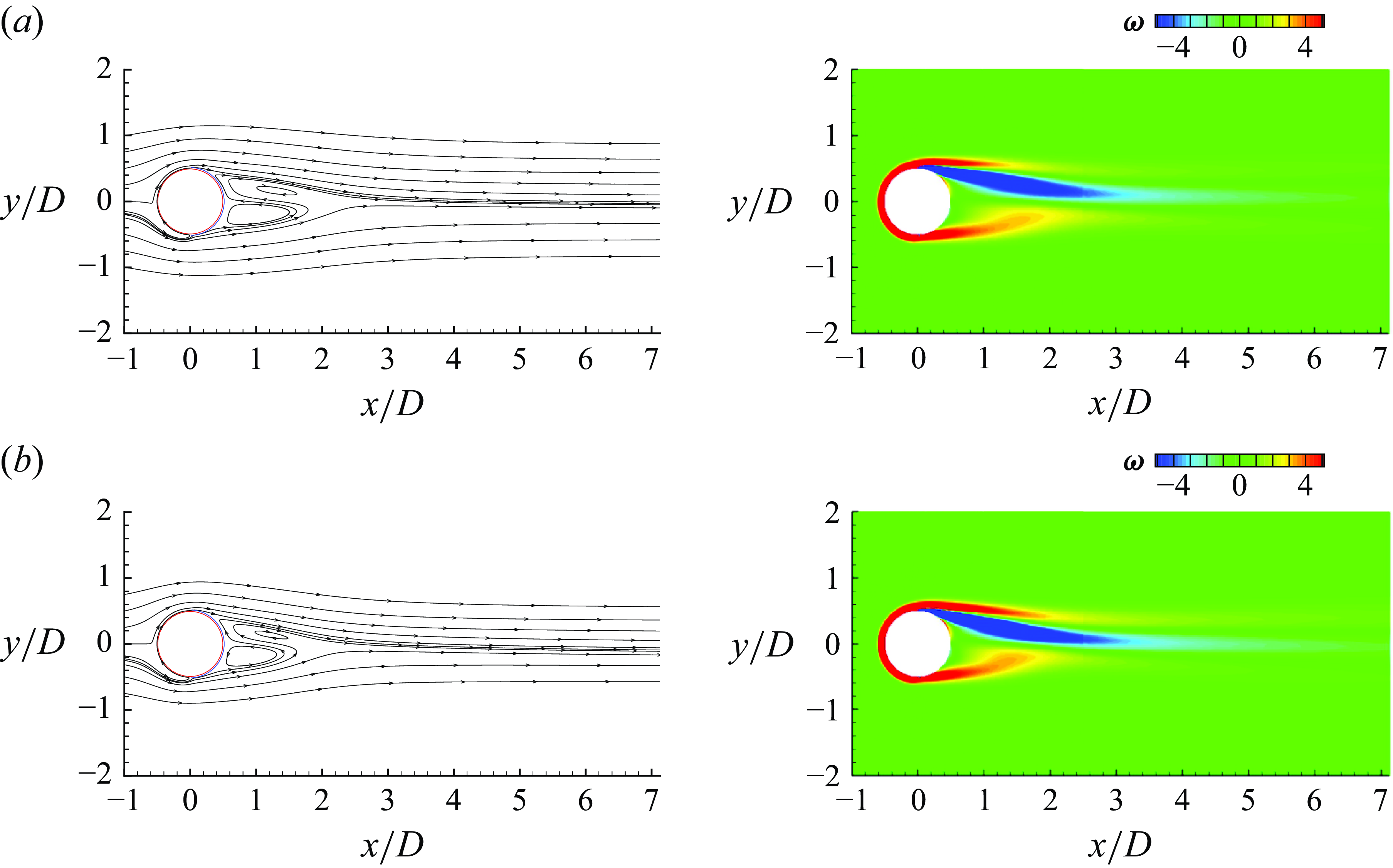
Figures 8–13 illustrate how vorticity and streamlines around the circular cylinder change with different
 $\alpha$
under RBH. At
 $\alpha =0$
, the upper half of the circular cylinder exhibits a negative vorticity, while the lower half exhibits a positive vorticity, as shown in figure 8. As
 $\alpha$
gradually increases, a positive vorticity appears on the upper left part of the circular cylinder when
 $\alpha$
reaches 1, as shown in figure 9. At
 $\alpha =2.75$
, both the lower part and the upper left part of the circular cylinder exhibit positive vorticity, as shown in figure 10. As
 $\alpha$
is further increased to 3.5, the range of positive vorticity on the upper part of the circular cylinder expands, as shown in figure 11. At
 $\alpha =4.11$
, the negative vorticity behind the circular cylinder is completely sandwiched between the two positive vorticity, as shown in figure 12. At
 $\alpha =4.2$
and 5, the vorticity above the circular cylinder is no longer shed, forming a dead water area behind the circular cylinder, as shown in figure 13. At a distance of 3
 $D$
from the centre of the circular cylinder, the streamlines are nearly horizontal and clearly visible. In general, as
 $\alpha$
increases from 0 to 5, the position of the separation point on the circular cylinder decreases from
 $63^{\circ }$
to
 $55^{\circ }$
, indicating a backward movement of the separation point, as shown in figure 6(b). The vorticity region behind the circular cylinder transitions from a fuller state at
 $\alpha =0$
to a flatter and longer state at
 $\alpha =5$
.
(Circular cylinder) Under RBH with
 $Re = 200$
and
 $\alpha =1$
: (a) time history of force coefficients; the flow visualisation demonstrating (b) streamlines and (c) vorticity.

(Circular cylinder) Under RBH with
 $Re = 200$
and
 $\alpha =2.75$
: (a) time history of force coefficients; the flow visualisation demonstrating (b) streamlines and (c) vorticity.

(Circular cylinder) Under RBH with
 $Re = 200$
and
 $\alpha =3.5$
: (a) time history of force coefficients; the flow visualisation demonstrating (b) streamlines and (c) vorticity.

(Circular cylinder) Under RBH with
 $Re = 200$
and
 $\alpha =4.11$
: (a) time history of force coefficients; the flow visualisation demonstrating (b) streamlines; (c) vorticity; (d) magnitude of the volume drag element
 $-2\boldsymbol {u}\times \boldsymbol {\omega }\cdot \boldsymbol {\nabla }\phi _{i}$
in (2.15) for the drag coefficient; and (e) magnitude of the volume lift element
 $-2\boldsymbol {u}\times \boldsymbol {\omega }\cdot \boldsymbol {\nabla }\phi _{j}$
in (2.20) for the lift coefficient.

(Circular cylinder) Under RBH with
 $Re = 200$
and various
 $\alpha$
, the flow visualisation demonstrating the streamlines (first column) and the vorticity (second column) at (a)
 $\alpha =4.2$
and (b)
 $\alpha =5$
.

The distribution of streamlines near the circular cylinder is analysed over a period of time. For flow past a stationary circular cylinder, the vortex periodically sheds in the upper and lower wake, with relatively fuller streamlines near the circular cylinder, as shown in figure 8(b). Under RBH, the circulation region surrounded by the streamlines in the wake is relatively flat and long, and the weak periodic oscillations in the flow field can also be seen in the weak amplitudes of the force coefficients, as shown in figure 12(b). Under RB, the streamlines near the circular cylinder are connected head to tail around the circle and the flow field remains constant, as shown in figure 14(a).
Next, FEA is used to correlate the vorticity around the circular cylinder with the drag coefficient and lift coefficient of the circular cylinder to investigate why the drag coefficient is reduced and the lift coefficient is kept at a low level. The FEA is an analytical method used to extract the volume vorticity force term from the forces acting on a bluff body. The volume drag element term
 $C_{DV}$
and the volume lift element term
 $C_{LV}$
quantify the contribution of the vorticity to drag and lift, respectively.
The specific expressions
 $C_{DV}$
and
 $C_{LV}$
can be found in table 1. Here,
 $\phi _i$
and
 $\phi _j$
are the potential function in the
 $\boldsymbol {i}$
-direction and
 $\boldsymbol {j}$
-direction, respectively, as listed in figure 2. The contour in figure 8(c,d) and figure 12(c,d) is coloured by the magnitude of the volume drag element
 $-2\boldsymbol {u}\times \boldsymbol {\omega } \cdot \nabla \phi _{i}$
and the volume lift element
 $-2\boldsymbol {u}\times \boldsymbol {\omega } \cdot \nabla \phi _{j}$
. The volume drag element
 $-2\boldsymbol {u}\times \boldsymbol {\omega }\cdot \boldsymbol {\nabla }\phi _{i}$
and the volume lift element
 $-2\boldsymbol {u}\times \boldsymbol {\omega }\cdot \boldsymbol {\nabla }\phi _{j}$
serve as the integrands for the volume drag term
 $C_{DV}=-2\int _{V_{R}}\boldsymbol {u}\times \boldsymbol {\omega }\cdot \boldsymbol {\nabla }\phi _{i}\mathrm {d}V$
and the volume lift term
 $C_{LV}=-2\int _{V_{R}}\boldsymbol {u}\times \boldsymbol {\omega }\cdot \boldsymbol {\nabla }\phi _{j}\mathrm {d}V$
, which are the most significant components of
 $C_D$
and
 $C_L$
, respectively, as listed in table 1. Here,
 $C_D^*$
and
 $C_L^*$
represent drag coefficient and lift coefficient obtained by FLUENT, respectively;
 $C_D$
and
 $C_L$
are the sum of the drag element terms and the sum of the lift element terms, respectively;
 $R_m$
indicates the difference between
 $C_D$
and
 $C_D^*$
(or
 $C_L$
and
 $C_L^*$
). The smallness of
 $R_m$
shows close agreements between
 $C_D$
and
 $C_D^*$
, and
 $C_L$
and
 $C_L^*$
.
For flow past a stationary circular cylinder, time instants
 $t_{B2}$
and
 $t_{B4}$
were selected, at which the drag coefficient reaches its maximum value and the lift coefficient reaches its minimum value, respectively. The volume drag element
 $-2\boldsymbol {u}\times \boldsymbol {\omega } \cdot \nabla \phi _{i}$
at the front side of the circular cylinder contributes negatively (region with blue colour) to the drag, while the volume drag element at the back side contributes positively (region with yellow or red colour) to the drag, as shown in figure 8(d). The volume lift element
 $-2\boldsymbol {u}\times \boldsymbol {\omega } \cdot \nabla \phi _{j}$
at the top region of the circular cylinder contributes positively (region with red colour) to the lift, while the volume lift element at the bottom region contributes negatively (region with blue colour) to the lift, as shown in figure 8(e). The contributions of the volume drag element term
 $C_{DV}$
and the surface drag element term
 $C_{DS}$
to the drag are 0.8631 and 0.5094, respectively, as listed in table 6. The contributions of the volume lift element term
 $C_{LV}$
and the surface drag element term
 $C_{LS}$
to the lift are −0.5530 and −0.1123, respectively, as listed in table 7. For flow past a stationary circular cylinder, the volume force element term is larger than the surface drag element term.


(Circular cylinder) Lift coefficient and its corresponding force elements in table 1 at some selected instants under SB, RB, RBH with
 $Re = 200$
and
 $\alpha = 4.11$
.

(Circular cylinder) Under RB with
 $Re = 200$
and
 $\alpha = 4.11$
, the flow visualisation demonstrating: (a) streamlines; (b) vorticity; (c) magnitude of the volume drag element
 $-2\boldsymbol {u}\times \boldsymbol {\omega }\cdot \boldsymbol {\nabla }\phi _{i}$
in (2.15) for the drag coefficient; and (d) magnitude of the volume lift element
 $-2\boldsymbol {u}\times \boldsymbol {\omega }\cdot \boldsymbol {\nabla }\phi _{j}$
in (2.20) for the lift coefficient.

As the circular cylinder rotates, the contribution of vorticity near the circular cylinder to drag and lift becomes complex. The rotating circular cylinder induces the rotation of the surrounding fluid. A larger velocity gradient results in stronger vorticity, indicating a greater contribution of volume force element term to the force coefficient. The contour representing the volume force element of the drag and lift in figures 12(d,e) and 14(c,d) has brighter colours than that in figure 8(d,e).
Under RBH, a time instant
 $t_{A3}$
is selected, at which the drag coefficient reaches its maximum value. It can be noticed that the positive contribution (region with red colour) to the drag coefficient around the circular cylinder is much larger than that of the negative contribution (region with blue colour). The volume drag element term
 $C_{DV}$
is 15.0930, which is much larger than that 0.8631 in the case of a stationary circular cylinder, as listed in table 6. (i) The volume drag element term
 $C_{DV}$
and the surface drag element term
 $C_{DS}$
under RBH at instant time
 $t_{A3}$
, compared with those in the SB at instant time
 $t_{B2}$
, are increased from 0.8631 to 15.0930 and from 0.5094 to 1.7866, respectively; however, the velocity drag element term
 $C_{DM}$
is largely reduced from 0 to −16.8617. Although the rotation of the front half of the circular cylinder makes the volume drag element term
 $C_{DV}$
very large and the surface drag element term
 $C_{DS}$
large, it introduces the velocity drag element term
 $C_{DM}$
making a great contribution to weakening the drag. (ii) The volume lift element term
 $C_{LV}$
and the surface lift element term
 $C_{LS}$
under RBH at instant time
 $t_{A6}$
, compared with those in the SB at instant time
 $t_{B4}$
, is increased from −0.5530 to 1.5627 and is reduced from −0.1123 to −1.5874, respectively. Although the rotation of the front half of the circular cylinder makes the volume lift element term
 $C_{LV}$
large, the surface lift element term
 $C_{LS}$
makes a great contribution to weakening the lift, as listed in table 7.
Under RB, the force coefficients are constant. It can be noticed that the positive contribution (region with red colour) to the lift around the circular cylinder is much larger than that of the negative contribution (region with blue colour), as shown in figure 14(d). The volume lift element term
 $C_{LV}$
is 17.2078, which is much larger than that −0.5530 in the case of a stationary circular cylinder, as listed in table 7. (i) The volume drag element term
 $C_{DV}$
and the surface drag element term
 $C_{DS}$
under RB, compared with those in the SB at instant time
 $t_{B2}$
, is reduced from 0.8631 to −1.2099 and is increased from 0.5094 to 1.2687, respectively. Although the rotation of the circular cylinder makes the surface drag element term
 $C_{DS}$
large, the volume drag element term
 $C_{DV}$
makes a contribution to weakening the drag. (ii) The volume lift element term
 $C_{LV}$
and the surface lift element term
 $C_{LS}$
under RB, compared with those in the SB at instant time
 $t_{B4}$
, is increased from −0.5530 to 17.2078 and from −0.1123 to 1.2708, respectively. The rotation of the total circular cylinder makes the volume lift element term
 $C_{LV}$
very large and the surface lift element term
 $C_{LS}$
large.
By reduction, it means that the force component along the flow direction is reduced, but without significantly incurring the other orthogonal components. The RB and RBH at
 $\alpha =4.11$
are extensively analysed using FEA for flow past a stationary circular cylinder. Under RBH, the drag is greatly reduced for the following reason: a large negative velocity drag element term
 $C_{DM}$
is introduced to offset the sharply increased volume drag element term
 $C_{DV}$
and slightly increased surface drag element term
 $C_{DS}$
. The lift is maintained at a small level for the following reason: a negative surface lift element term
 $C_{LS}$
counteracts the increased volume lift element term
 $C_{LV}$
. Under RB, the drag is greatly reduced for the following reason: a negative volume drag element term
 $C_{DV}$
offsets the slightly increased surface drag element term
 $C_{DS}$
in the drag. The lift is increased sharply for the following reasons: dramatically increased volume lift element term
 $C_{LV}$
and the slightly increased surface lift element term
 $C_{LS}$
.
(Circular cylinder) Surface pressure distribution of the circular cylinder under (a) SB, (b) RB and (c) RBH.

3.1.3. Surface pressure distribution (circular cylinder)
Pressure plus friction force analysis is of course a powerful (and traditional) analysis for identifying form drag/lift and in particular through surface force analysis. This approach has not been pursued too much in this study (to save space), as we have highlighted in the title ‘from the perspective of force element analysis’. In fact, in our previous work (Lee et al. Reference Lee, Hsieh, Chang and Chu2012), we did this side by side (pressure-friction versus force element analysis) and showed that it is sufficient to adopt one of the two alternatives. Our thought begins with the fact: body force is due to body motion, and motion directly generates velocity and vorticity which in turn results in pressure distribution on the body surface and within the flow. It is noticed that surface frictional force is relatively quite small, so we focus on the examination of the surface pressure distribution.
This section examines the pressure coefficient
 $C_P$
on the surface of the circular cylinder under SB, RB and RBH. Since the pressure in this paper is dimensionless according to
 $\rho U_\infty ^2$
, the pressure coefficient
 $C_P$
on the surface of the circular cylinder and the sphere are defined as
 \begin{equation} C_P=\dfrac {P^*(\theta )-P^*(0)}{\rho U_\infty ^2} \; \quad \mbox {at} \; r=D/2 \end{equation}
and
 \begin{equation} C_P=\dfrac {P^*(\Phi ,\theta )-P^*(0,0)}{\rho U_\infty ^2} \; \quad \mbox {at} \; r=D/2, \end{equation}
respectively. The coordinates of the reference pressure points on the surfaces of the circular cylinder and the sphere are (
 $D$
/2, 0) and (
 $D$
/2, 0, 0), respectively. The pressure values at these points are
 $P^*(\theta )$
and
 $P^*(\Phi ,\theta )$
, respectively;
 $P^*(\theta )$
and
 $P^*(\Phi ,\theta )$
represent the pressure on the surfaces of the circular cylinder and the sphere, respectively.
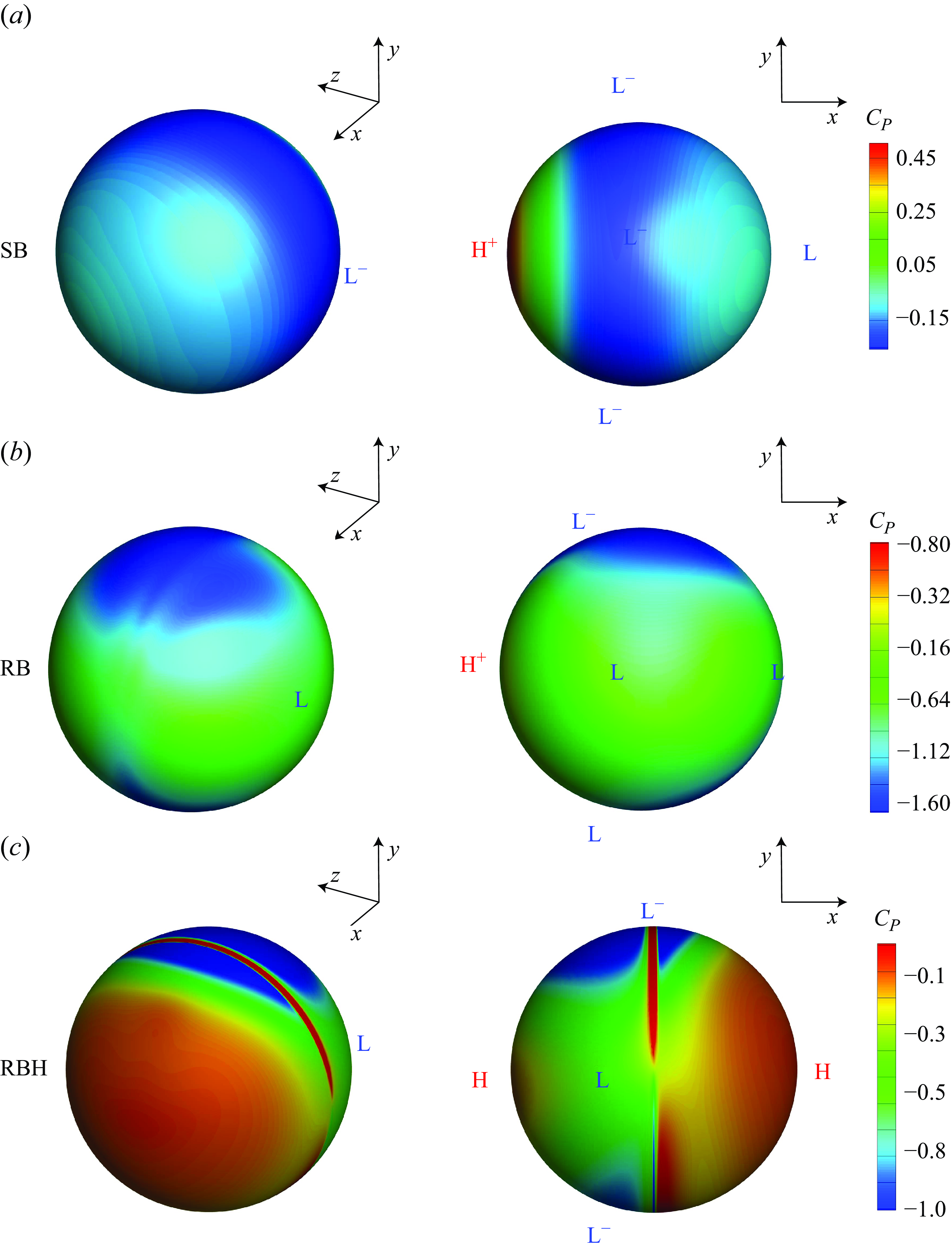
It is evident from the
 $C_P$
colour plots that the
 $C_P$
distributions are much different among the cases SB, RB and RBH. In particular, the locations of higher, high, low and lower
 $C_P$
are marked as H
 $^+$
, H, L and L
 $^-$
, respectively.
In the case of SB,
 $C_P$
exhibits higher values on the front surface, indicating substantial drag, yet, the
 $C_P$
distribution is roughly symmetric about the x-axis, suggesting a small
 $C_L$
, as shown in figure 15(a).
In the case of RB (Magnus effect),
 $C_P$
has higher values on the lower surface, signifying a substantial lift, yet the
 $C_P$
distribution is somewhat symmetric about the y-axis, indicating a small value of
 $C_L$
, as shown in figure 15(b).
In the case of RBH (half-rotation),
 $C_P$
has lower and comparable values on both upper and lower surfaces, yet in contrast,
 $C_P$
has higher and comparable values on both front and rear surfaces. This outstanding distribution results in small values of both
 $C_D$
and
 $C_L$
, a simultaneous reduction of drag and lift, as shown in figure 15(c).
3.2.
Simultaneous reduction of drag and lift for the sphere at
$Re$
= 200 and
$Re$
= 300


In this section, the drag reduction problem of flow around a stationary sphere is studied at
 $Re$
= 200 and
 $Re$
= 300. This involves the steady axisymmetric flow at
 $Re$
= 200 and the unsteady plane-symmetric flow at
 $Re$
= 300 (Yun, Kim & Choi Reference Yun, Kim and Choi2006). The effects of RB and the drag reduction method RBH with
 $0 \leqslant \alpha \leqslant 7$
are analysed. For RBH and RB at a fixed rotational speed, FEA was used to analyse the force coefficient of the sphere and the flow field around the sphere in detail, and to provide reasons for the drag and lift reduction.
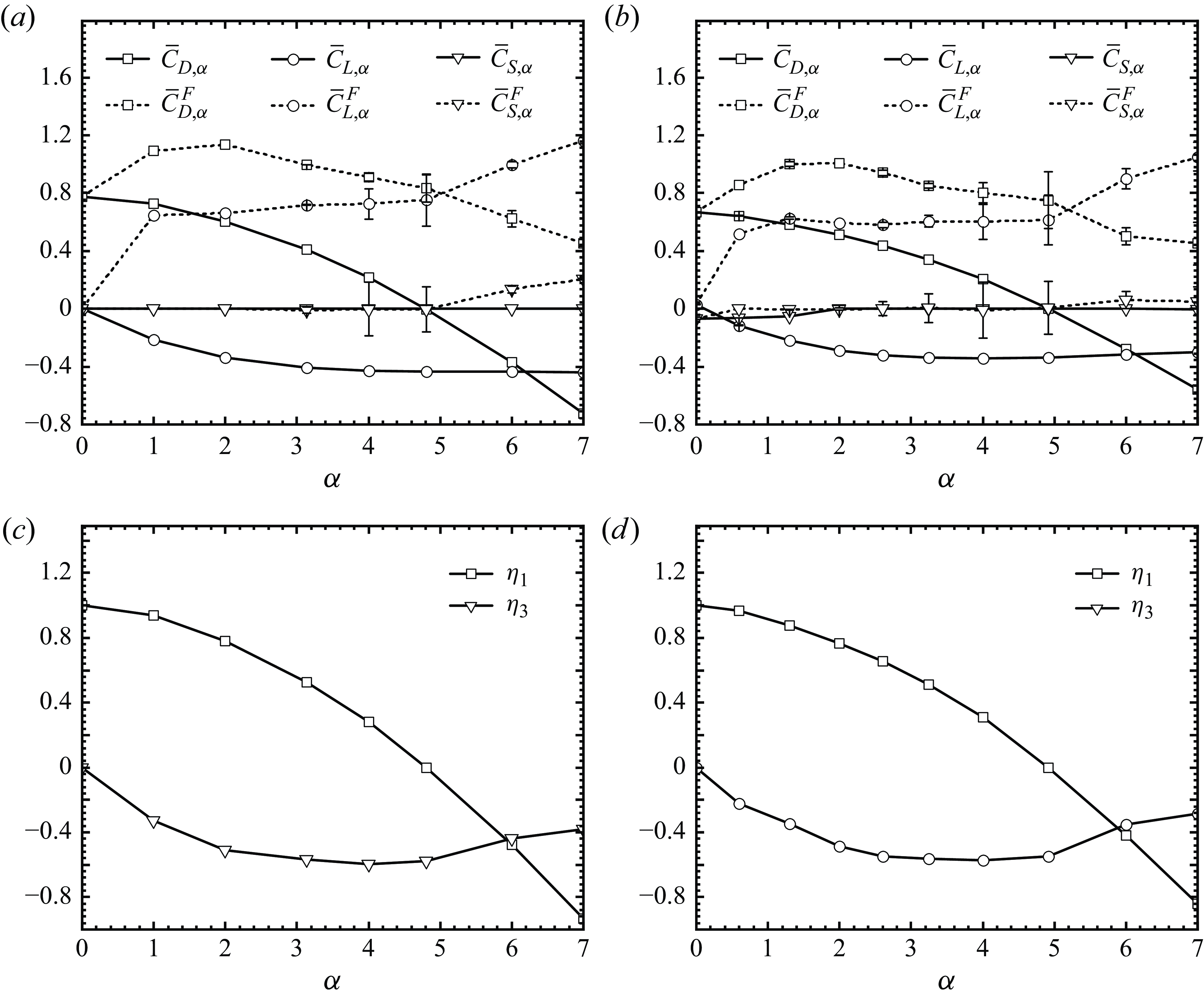
(Sphere) (a,b) Force coefficients and (c,d) two ratios (the drag reduction ratio
 $\eta _1$
and the mean lift ratio
 $\eta _3$
) measuring the effectiveness of drag reduction with respect to the different rotating speed
 $\alpha$
at the Reynolds number (a,c)
 $Re$
= 200 and (b,d)
 $Re$
= 300. The error bars indicate the amplitude
 $A_{D}$
of oscillation in the drag coefficient
 $C_D$
or the amplitude
 $A_{L}$
of oscillation in the lift coefficient
 $C_L$
.

3.2.1. Force coefficients of the sphere at different rotation speed
This section primarily discusses the characteristics of the force coefficients of the sphere at different rotational speeds to demonstrate the advantages of RBH. Figure 16 depicts the evolution of the force coefficients (mean value and amplitude) and two ratios (the drag reduction ratio
 $\eta _1$
and the mean lift ratio
 $\eta _3$
) with respect to various
 $\alpha$
.
Under RBH, as
 $\alpha$
increases from 0 to 7: (i) the mean drag coefficient
 $\bar {C}_{D,\alpha }$
decreases monotonically from 0.7788 to −0.7231 at
 $Re$
= 200 and from 0.6651 to −0.5593 at
 $Re = 300$
; (ii) the mean lift coefficient
 $\bar {C}_{L,\alpha }$
decreases monotonically from 0.0043 to −0.4402 at
 $Re$
= 200 and from 0.0732 to −0.3002 at
 $Re = 300$
; (iii) the side force coefficient is maintained at approximately 0; (iv) the amplitude of the force coefficients rapidly decreases to zero; (v) in addition, the drag coefficient decreases sharply while the lift coefficient of the sphere changes weakly at
 $4 \leqslant \alpha \leqslant 7$
, as shown in figure 16(a,b).
Under RB, as
 $\alpha$
increases from 0 to 7: (i) for
 $Re$
= 200, the mean drag coefficient
 $\bar {C}_{D,\alpha }^F$
increases monotonically from 0.7760 to 1.1361(
 $\alpha =2$
) and then decreases monotonically to 0.4549; the mean lift coefficient
 $\bar {C}_{L,\alpha }^F$
increases from 0 to 1.1620, as shown in figure 16(a); (ii) for
 $Re$
= 300, the mean drag coefficient
 $\bar {C}_{D,\alpha }^F$
increases monotonically from 0.6651 to 1.006 (
 $\alpha =2$
) and then decreases monotonically to 0.4515; the mean lift coefficient
 $\bar {C}_{L,\alpha }^F$
increases from 0.0301 to 1.0515, as shown in figure 16(b).
As
 $\alpha$
increases from 0 to 7, the drag reduction ratio
 $\eta _1$
decreases, indicating a progressive reduction in the average drag coefficient; the mean lift ratio
 $\eta _3$
decreases to negative first and then increases, indicating that the mean lift coefficient obtained using the drag reduction method RBH is less than that obtained using RB, as shown in figure 16(c,d). Under RBH, using the data in figure 16(a,b), we may locate an optimal
 $\alpha = \alpha _I$
= 4.81 for
 $Re$
= 200 and
 $\alpha = \alpha _I$
= 4.92 for
 $Re = 300$
, at which
 $\bar {C}_{D, \alpha }$
equals 0.
Under RBH: (i) for
 $Re$
= 200, the drag coefficient of the sphere decreases from
 $C_{D,0}^F=0.7780$
to
 $\bar {C}_{D,4.81}=0$
; the drag coefficient, compared with that of a stationary sphere, are reduced by 100
 $\%$
in the value from 0.7780 to 0; the lift coefficient of the sphere decreases from
 $C_{L,0}^F=0.0015$
to
 $C_{L,4.81}$
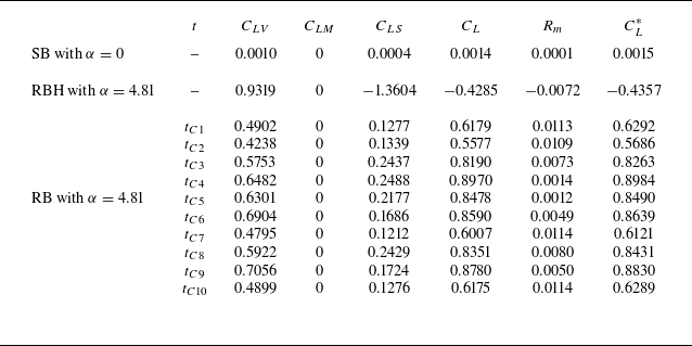
= −0.4357, as listed in tables 8 and 9; (ii) for
 $Re = 300$
, the drag coefficient of the sphere decreases from
 $C_{D,0}^F$
with mean value
 $\bar {C}_{D,0}^F=0.6651$
and amplitude
 $A_{D,0}^F=0.0016$
to
 $C_{D,4.92}=0$
; the lift coefficient of the sphere decreases from
 $C_{L,0}^F$
with mean value
 $\bar {C}_{L,0}^F=0.0302$
and amplitude
 $A_{L,0}^F=0.0032$
to
 $C_{L,4.92}$
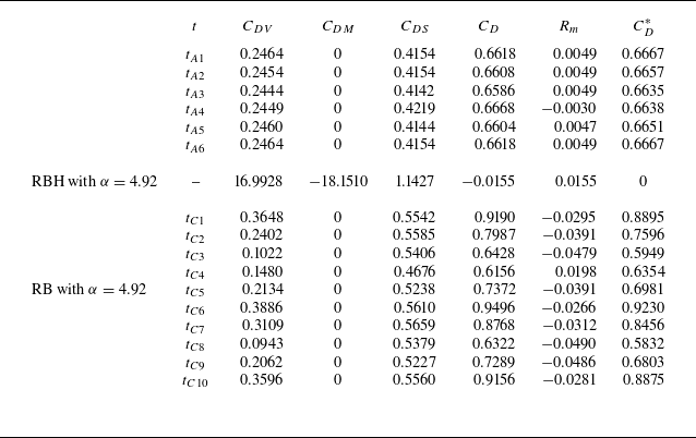
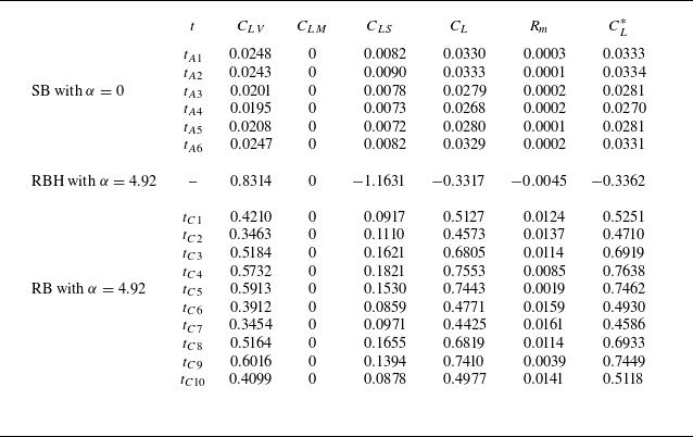
= −0.3362, as listed in tables 10 and 11.


(Sphere) Force element terms of lift coefficient in table 1 at some selected instants under SB, RB, RBH with
 $Re = 200$
and
 $\alpha = 4.81$
.

(Sphere) Force element terms of drag coefficient in table 1 at some selected instants under SB, RB, RBH with
 $Re = 300$
and
 $\alpha = 4.92$
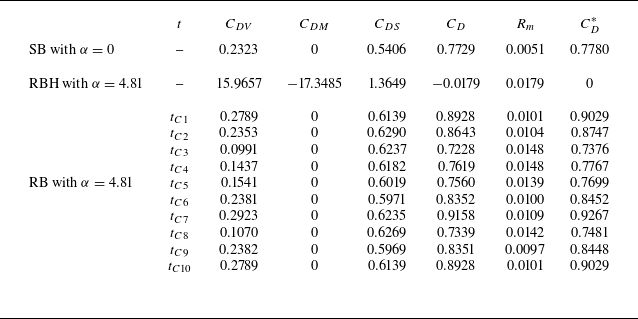
. The instant times from
 $t_{A1}$
to
 $t_{A6}$
is presented in figure 18(a). The instant times from
 $t_{C1}$
to
 $t_{C10}$
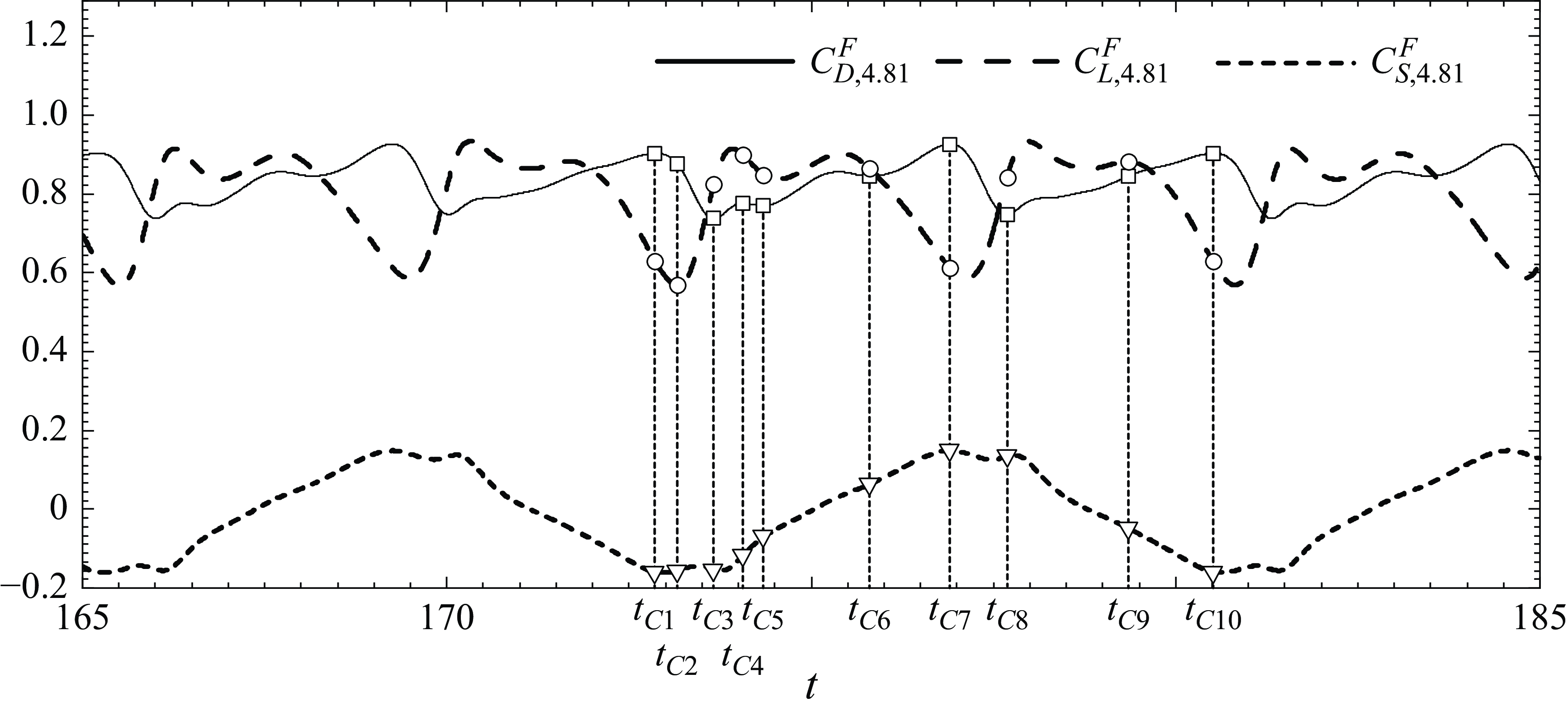
is presented in figure 21(a).

(Sphere) Force element terms of lift coefficient in table 1 at some selected instants under SB, RB, RBH with
 $Re = 300$
and
 $\alpha = 4.92$
.

Under RB: (i) for
 $Re$
= 200, the drag coefficient of the sphere increases from
 $C_{D,0}^F=0.7780$
to
 $\bar {C}_{D,4.81}^F$
with mean value
 $\bar {C}_{D,4.81}^F=0.8321$
and amplitude
 $A_{D,4.81}^F=0.0946$
; the lift coefficient of the sphere increases from
 $C_{L,0}^F=0.0015$
to
 $C_{L,4.81}^F$
with mean value
 $\bar {C}_{L,4.81}^F=0.7335$
and amplitude
 $A_{L,4.81}^F=0.1649$
, as listed in tables 8 and 9; (ii) for
 $Re$
= 300, the drag coefficient of the sphere increases from
 $C_{D,0}^F$
with mean value
 $\bar {C}_{D,0}^F=0.6651$
and amplitude
 $A_{D,0}^F=0.0016$
to
 $\bar {C}_{D,4.92}^F$
with mean value
 $\bar {C}_{D,4.92}^F=0.7531$
and amplitude
 $A_{D,4.92}^F=0.1699$
; the lift coefficient of the sphere increases from
 $C_{L,0}^F$
with mean value
 $\bar {C}_{L,0}^F=0.0302$
and amplitude
 $A_{L,0}^F=0.0032$
to
 $\bar {C}_{L,4.92}^F$
with mean value
 $\bar {C}_{L,4.92}^F=0.6112$
and amplitude
 $A_{L,4.92}^F=0.1526$
, as listed in tables 10 and 11.
(Sphere) Force coefficients (
 $C_D (t)$
,
 $C_L(t)$
,
 $C_S(t)$
) in the windows of
 $165\leqslant t \leqslant 185$
instants under RB with
 $Re = 200$
and
 $\alpha = 4.81$
.

(Sphere) (a) Force coefficients (
 $C_D (t)$
,
 $C_L(t)$
,
 $C_S(t)$
) of the sphere in the windows of
 $1300\leqslant t \leqslant 1340$
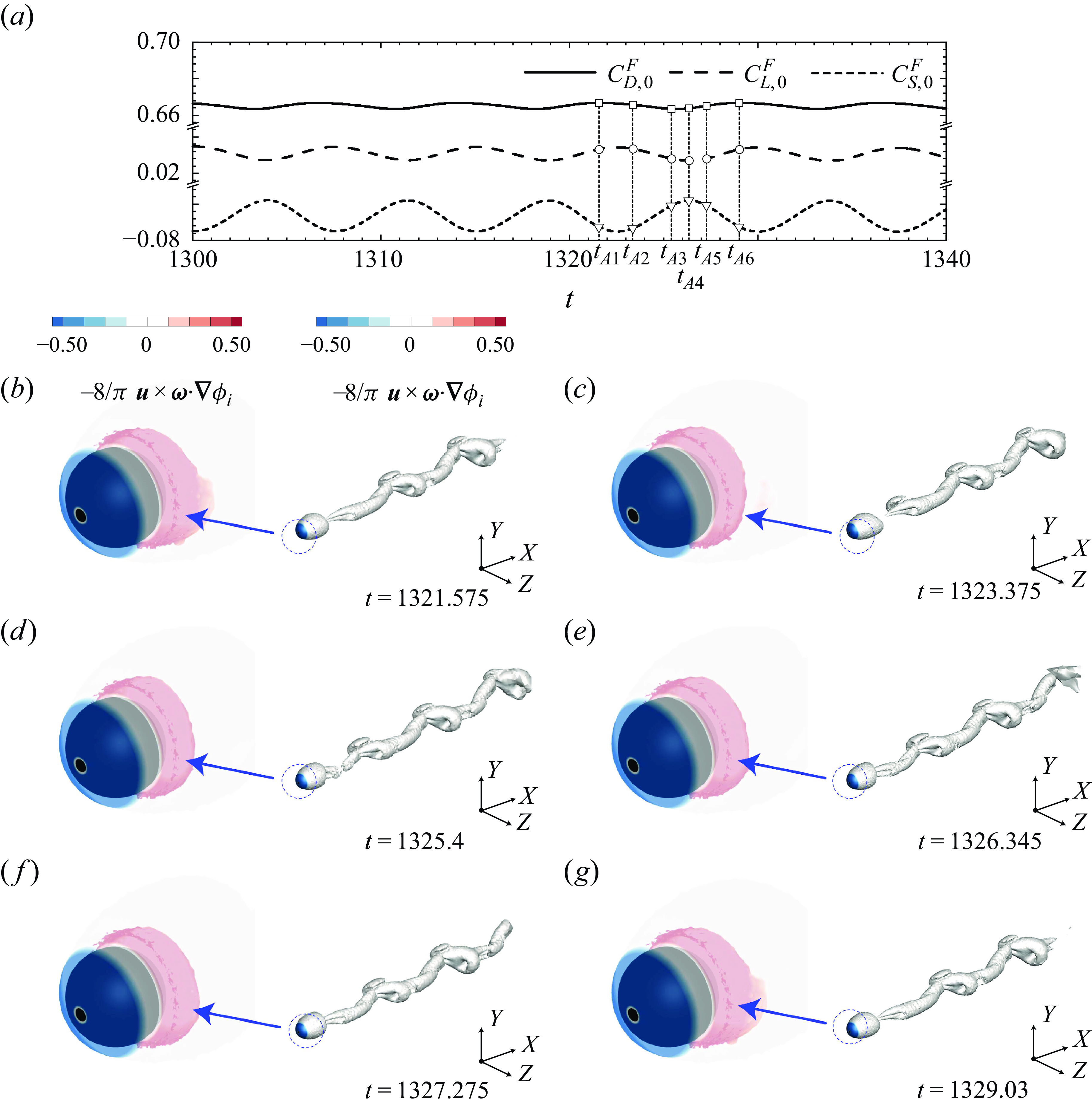
. (b–g) Vorticity in Q-plot at selected instants under SB with
 $Re = 300$
. The vorticity contours and local transparent enlarged view demonstrate the magnitude of volume drag element
 $- ({8}/{\pi }) \boldsymbol {u}\times \boldsymbol {\omega }\cdot \boldsymbol {\nabla }\phi _{i}$
in (2.15) for the drag coefficient.

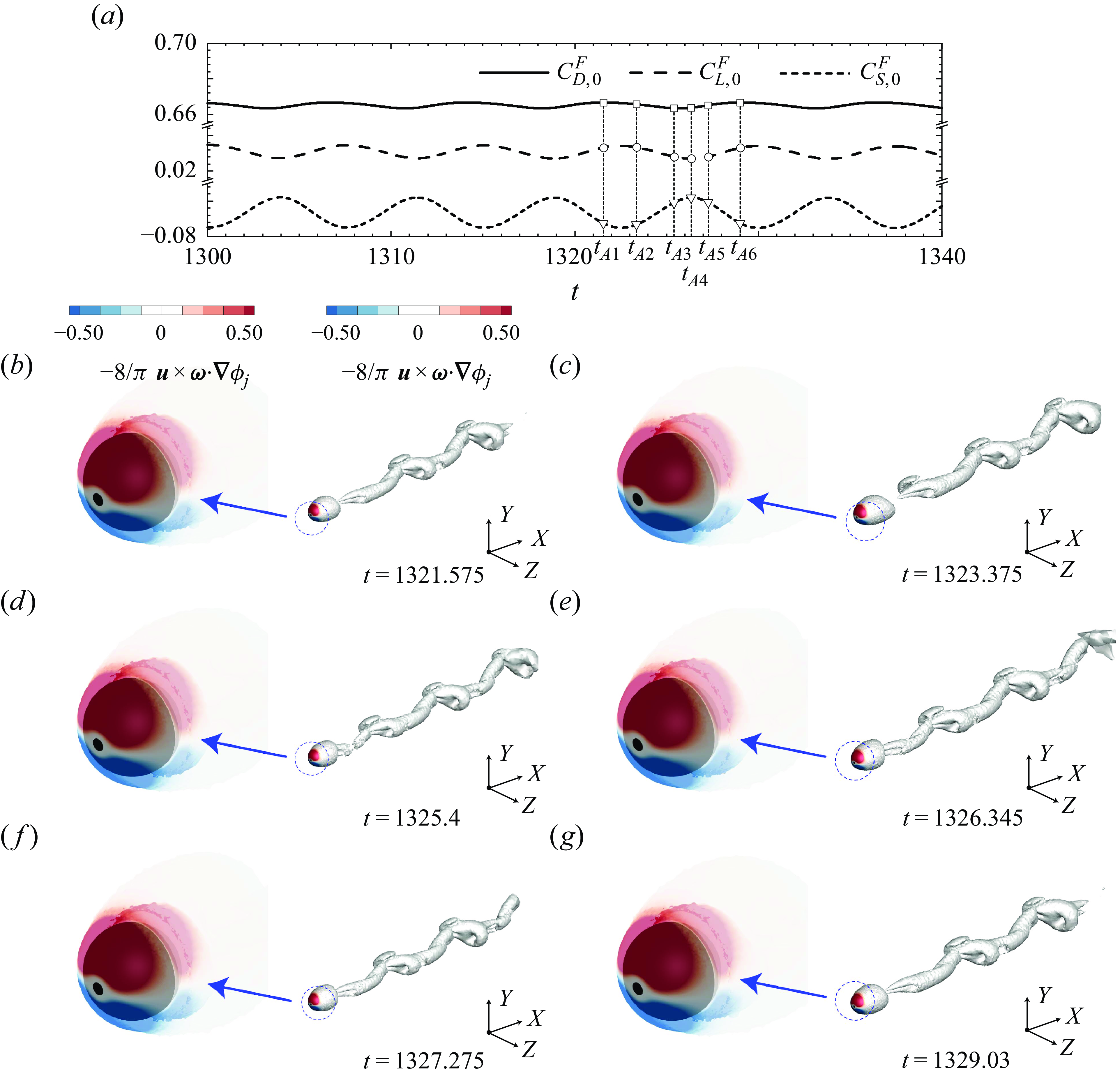
(Sphere) (a) Force coefficients (
 $C_D (t)$
,
 $C_L(t)$
,
 $C_S(t)$
) in the windows of
 $1300\leqslant t \leqslant 1340$
. (b–g) Vorticity in Q-plot at selected instants under SB with
 $Re = 300$
. The vorticity contours and local transparent enlarged view demonstrate the magnitude of volume lift element
 $- ({8}/{\pi }) \boldsymbol {u}\times \boldsymbol {\omega }\cdot \boldsymbol {\nabla }\phi _{j}$
in (2.20) for the lift coefficient.

As mentioned above, using the optimal rotation speed
 $\alpha _I=4.81$
for
 $Re$
= 200 and
 $\alpha _I=4.92$
for
 $Re = 300$
, the advantages of RBH are thoroughly analysed. Considering the effect of drag reduction, RBH demonstrates greater advantages.
3.2.2. Analysing lift and drag of the sphere by force element theory
Although the sphere is a highly symmetric, structurally simple three-dimensional geometry, a wide variety of vortex patterns appear in the wake when the Reynolds number increases.
First, the variation of the flow field is analysed by examining the changes in the vorticity pattern. For flow past a stationary sphere, the flow field presents a steady axisymmetry with vortex ring at
 $Re$
= 200 and an unsteady plane-symmetry with constant strength of the hairpin vortices periodically shedding in the wake at
 $Re$
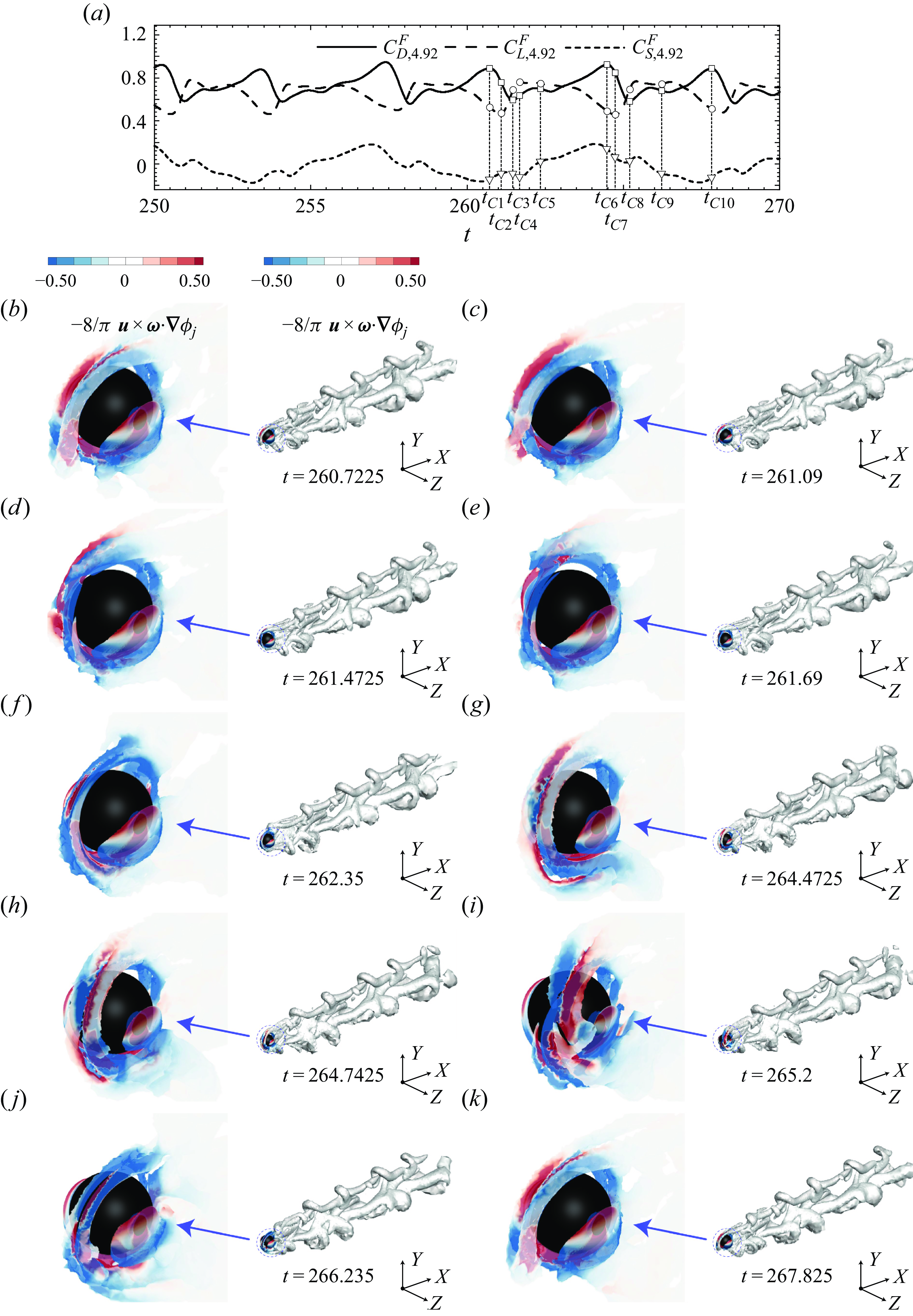
= 300 (Yun et al. Reference Yun, Kim and Choi2006). Figures 18 and 19 illustrate the changes in vorticity at six specific time instants during a vortex shedding cycle for flow past a stationary sphere, highlighting the periodic downstream shedding of the hairpin vortex. When RB is used, the sphere rotates around the transverse axis, driving the surrounding fluid motion and causing complex changes in the flow field. Figures 21 and 22 show the changes in vorticity at ten specific time instants in a vortex shedding cycle when RB is used with
 $\alpha = 4.92$
. Although the vorticity presents a certain periodicity, the variation is complicated. When RBH is applied, specifically with the sphere rotating around its transverse axis while a stationary hood is placed over the rear half, and
 $\alpha$
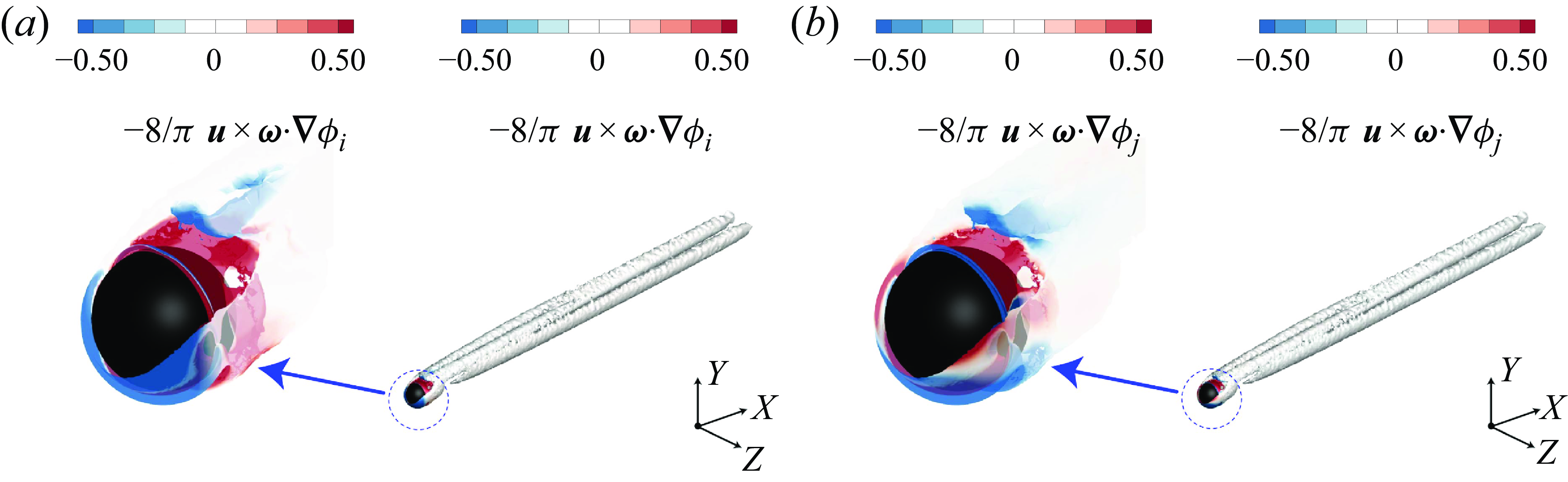
exceeds 0.6, the force coefficients of the sphere stabilise, vortex shedding is suppressed, and the flow field rapidly achieves a steady, plane-symmetric state with a double-threaded structure. Figure 20 illustrates the vorticity distribution around the sphere when RBH is implemented at a rotation speed of 4.92.
Second, changes in the force coefficients and flow field are analysed using FEA to elucidate the reason for drag and lift reduction. Figure 3 depicts the auxiliary potential flows
 $\phi _{i}$
and
 $\phi _{j}$
in the
 $x$
-direction and
 $y$
-direction, respectively. In figures 18–22, the vorticity are identified by defining iso-surfaces using the Q-criterion method of the level 0.0015. The Q-criterion (Hunt, Wray & Moin Reference Hunt, Wray and Moin1988) is defined by
 $ Q \equiv 1/2 ( \Omega ^{2}-S ^{2} )$
, where
 $ \Omega$
and
 $ S$
are the square norms
 $\Omega =\sqrt {2\Omega _{ij}\Omega _{ij}}$
and
 $S=\sqrt {2 S_{ij}S_{ij}}$
with the vorticity tensor
 $\Omega _{ij}= ({1}/{2}) (\partial v_{i}/\partial x_{j}-\partial v_{j}/\partial x_{i} )$
and the strain rate tensor
 $S_{ij}=1/2 (\partial v_{i}/\partial x_{j}+\partial v_{j}/\partial x_{i} )$
. The vorticity contours and local transparent enlarged view is coloured by the magnitude of the volume drag element
 $-({8}/{\pi })\boldsymbol {u}\times \boldsymbol {\omega }\cdot \boldsymbol {\nabla }\phi _{i}$
for the drag coefficient and the volume lift element
 $-({8}/{\pi }) \boldsymbol {u}\times \boldsymbol {\omega }\cdot \boldsymbol {\nabla }\phi _{j}$
for the lift coefficient. The volume drag element
 $-({8}/{\pi }) \boldsymbol {u}\times \boldsymbol {\omega }\cdot \boldsymbol {\nabla }\phi _{i}$
and the volume lift element
 $-({8}/{\pi }) \boldsymbol {u}\times \boldsymbol {\omega }\cdot \boldsymbol {\nabla }\phi _{j}$
serve as the integrands for the volume drag term
 $C_{DV}=-({8}/{\pi }) \int _{V_{R}}\boldsymbol {u}\times \boldsymbol {\omega }\cdot \boldsymbol {\nabla }\phi _{i}\mathrm {d}V$
and the volume lift term
 $C_{LV}=-({8}/{\pi }) \int _{V_{R}}\boldsymbol {u}\times \boldsymbol {\omega }\cdot \boldsymbol {\nabla }\phi _{j}\mathrm {d}V$
, which are the most significant components of the drag coefficient
 $C_D$
and the lift coefficient
 $C_L$
, respectively, as shown in table 1.
(Sphere) Vorticity in Q-plot at a selected instant under RBH with
 $Re = 300$
and
 $\alpha = 4.92$
. The vorticity contours and local transparent enlarged view demonstrate the magnitude: (a) of the volume drag element
 $-({8}/{\pi }) \boldsymbol {u}\times \boldsymbol {\omega }\cdot \boldsymbol {\nabla }\phi _{i}$
in (2.15) for the drag coefficient and (b) of the volume lift element
 $-({8}/{\pi }) \boldsymbol {u}\times \boldsymbol {\omega }\cdot \boldsymbol {\nabla }\phi _{j}$
in (2.20) for the lift coefficient.

(Sphere) (a) Force coefficients (
 $C_D (t)$
,
 $C_L(t)$
,
 $C_S(t)$
) in the windows of
 $250\leqslant t \leqslant 270$
. (b–k) Vorticity in Q-plot at selected instants under RB with
 $Re = 300$
and
 $\alpha = 4.92$
. The vorticity contours and local transparent enlarged view demonstrate the magnitude of volume drag element
 $-({8}/{\pi }) \boldsymbol {u}\times \boldsymbol {\omega }\cdot \boldsymbol {\nabla }\phi _{i}$
in (2.15) for the drag coefficient.

(Sphere) (a) Force coefficients (
 $C_D (t)$
,
 $C_L(t)$
,
 $C_S(t)$
) in the windows of
 $250 \leqslant t \leqslant 270$
. (b–k) Vorticity in Q-plot at selected instants under RB with
 $Re = 300$
and
 $\alpha = 4.92$
. The vorticity contours and local transparent enlarged view demonstrate the magnitude of volume lift element
 $-({8}/{\pi }) \boldsymbol {u}\times \boldsymbol {\omega }\cdot \boldsymbol {\nabla }\phi _{j}$
in (2.20) for the lift coefficient.

For flow past a stationary sphere at
 $Re$
= 300, the volume drag element
 $-({8}/{\pi }) \boldsymbol {u}\times \boldsymbol {\omega } \cdot \nabla \phi _{i}$
at the front side of the sphere contributes negatively (region with blue colour) to the drag, while the volume drag element at the rear side of the sphere contributes positively (region with red colour) to the drag, as shown in figure 18; the volume lift element
 $-({8}/{\pi }) \boldsymbol {u}\times \boldsymbol {\omega } \cdot \nabla \phi _{j}$
at the top region of the sphere contributes positively (region with red colour) to the lift, while the volume lift element at the bottom region contributes negatively (region with blue colour) to the lift, as shown in figure 19. For
 $Re$
= 300, the volume drag element term
 $C_{DV}$
and the surface drag element term
 $C_{DS}$
have the mean values 0.2456 and 0.4161, respectively, as listed in table 10; the volume lift element term
 $C_{LV}$
and the surface lift element term
 $C_{LS}$
are 0.0224 and 0.0080, respectively, as listed in table 11. For
 $Re$
= 200, the volume drag element term
 $C_{DV}$
and the surface drag element term
 $C_{DS}$
are 0.2323 and 0.5406, respectively, as listed in table 8; the volume lift element term
 $C_{LV}$
and the surface lift element term
 $C_{LS}$
are 0.0010 and 0.0004, respectively, as listed in table 9. For flow past a stationary sphere, the value of volume drag element term
 $C_{DV}$
is smaller than the surface drag element term
 $C_{DS}$
for the drag coefficient, while the value of volume lift element term
 $C_{LV}$
is larger than the surface lift element term
 $C_{LS}$
for the lift coefficient.
As the sphere rotates along the negative
 $z$
-axis at different speeds
 $\alpha$
, the contribution of the vorticity near the sphere to lift and drag becomes complex. The rotating sphere induces the rotation of the surrounding fluid. A larger velocity gradient results in stronger vorticity, indicating a greater contribution of the volume force element term to the force coefficient. In figure 20(a) of RBH and figure 21 of RB, the contours representing the volume drag element
 $-({8}/{\pi }) \boldsymbol {u}\times \boldsymbol {\omega } \cdot \nabla \phi _{i}$
of the drag have brighter colours than that in figure 18 of the SB for
 $Re$
= 300.
Under RBH, the force coefficients are constant. It can be noticed that the positive contribution (region with red colour) to the drag coefficient around the sphere is much larger than that of the negative contribution (region with blue colour), as shown in figure 20(a) for
 $Re$
= 300 at
 $\alpha$
= 4.92.
For
 $Re$
= 200 at
 $\alpha$
= 4.81: (i) the volume drag element term
 $C_{DV}$
and the surface drag element term
 $C_{DS}$
under RBH, compared with those in the SB, are increased from 0.2323 to 15.9657 and from 0.5406 to 1.3649, respectively; however, the velocity drag element term
 $C_{DM}$
is largely reduced from 0 to −17.3485, as listed in table 8; (ii) the volume lift element term
 $C_{LV}$
and the surface lift element term
 $C_{LS}$
under RBH, compared with those in the SB, are increased from 0.0010 to 0.9319 and reduced from 0.0004 to −1.3604, respectively, as listed in table 9.
For
 $Re$
= 300 at
 $\alpha$
= 4.92: (i) the volume drag element term
 $C_{DV}$
and the surface drag element term
 $C_{DS}$
under RBH, compared with those in the SB, are increased from a mean value 0.2456 to a constant 16.9928 and from a mean value 0.4161 to a constant 1.1427, respectively; however, the velocity drag element term
 $C_{DM}$
is largely reduced from 0 to −18.1510, as listed in table 10; (ii) the volume lift element term
 $C_{LV}$
and the surface lift element term
 $C_{LS}$
under RBH, compared with those in the SB, are increased from a mean value 0.0224 to a constant 0.8314 and reduced from a mean value 0.0080 to a constant −1.1631, respectively, as listed in table 11.
Although RBH makes the volume drag element term
 $C_{DV}$
very large, it introduces the negative velocity drag element term
 $C_{DM}$
making a great contribution to weakening the drag of the sphere. Although RBH makes the volume lift element term
 $C_{LV}$
large, the surface lift element term
 $C_{LS}$
makes a great contribution to weakening the lift of the sphere.
Under RB, the force coefficients are not constant. For
 $Re$
= 200 at
 $\alpha$
= 4.81: (i) the volume drag element term
 $C_{DV}$
and the surface drag element term
 $C_{DS}$
under RB, compared with those in the SB, are decreased from a constant 0.2323 to a mean value 0.2066 and increased from a constant 0.5406 to a mean value 0.6145, respectively, as listed in table 8; (ii) the volume lift element term
 $C_{LV}$
and the surface lift element term
 $C_{LS}$
under RB, compared with those in the SB, are increased from a constant 0.0010 to a mean value 0.5725 and from a constant 0.0004 to a mean value 0.1805, respectively, as shown in table 9. For
 $Re$
= 300 at
 $\alpha$
= 4.92: (i) the volume drag element term
 $C_{DV}$
and the surface drag element term
 $C_{DS}$
under RB, compared with those in the SB, are decreased from a mean value 0.2456 to a mean value 0.2428 and increased from a mean value 0.4161 to a mean value 0.5388, respectively, as listed in table 10; (ii) the volume lift element term
 $C_{LV}$
and the surface lift element term
 $C_{LS}$
under RB, compared with those in the SB, are increased from a mean value 0.0224 to a mean value 0.4715 and from 0.0080 to a mean value 0.1276, respectively, as listed in table 11.
(Sphere) Surface pressure distribution of the sphere under (a) SB, (b) RB and (c) RBH.

The rotation of the sphere does not change the volume drag element term
 $C_{DV}$
and the surface drag element term
 $C_{DS}$
much, but it does make the volume lift element term
 $C_{LV}$
and the surface lift element term
 $C_{LS}$
in the lift coefficient large.
In summary, flow past a stationary sphere (SB with
 $Re$
= 200 and
 $Re$
= 300; and RBH and RB with
 $Re$
= 200 at
 $\alpha$
= 4.81 and
 $Re$
= 300 at
 $\alpha$
= 4.92) are extensively analysed using FEA. In RBH, the drag is greatly reduced for the following reasons: a large negative velocity drag element term
 $C_{DM}$
is introduced to offset the sharply increased volume drag element term
 $C_{DV}$
and the slightly increased surface drag element term
 $C_{DS}$
. The lift changes to negative for the following reason: the negative surface lift element term
 $C_{LS}$
counteracts the increased volume lift element term
 $C_{LV}$
in the lift. Under RB, the effect of drag reduction is not good and the drag begins to decrease at
 $\alpha \geqslant 5$
. The lift is increased sharply for the following reasons: dramatically increased volume lift element term
 $C_{LV}$
and the slightly increased surface lift element term
 $C_{LS}$
.
3.2.3. Surface pressure distribution (sphere)
This section examines the pressure coefficient on the surface of the sphere under SB, RBH and RB. The pressure coefficient, as given by (3.2), is shown in the distribution on the surface of the sphere in figure 23. In the colour
 $C_P$
plots for the sphere, the locations of higher, high, low and lower
 $C_P$
are marked as H
 $^+$
, H, L and L
 $^-$
, respectively.
Similar to the cases for the circular cylinder, the
 $C_P$
distribution leads to a substantial
 $C_D$
and a small
 $C_L$
for SB, a significant
 $C_D$
and
 $C_L$
(along with a small side force) for RB, and a simultaneous reduction of the force coefficients in all the three directions, naturally including
 $C_D$
and
 $C_L$
, for RBH.
It is noticed that in the case of RBH, there is a sharp change in
 $C_P$
(spike) in a narrow region, which has little contribution to the entire force on the sphere. The spike is across the interface between the rotating and non-rotating surfaces. The letter H, L
 $^-$
or L we have marked for
 $C_P$
neglects this sharp change, and is determined by the trend of
 $C_P$
in the neighbouring region of the spike.
4. Concluding remarks
Full rotation, the Magnus effect, for a circular cylinder or a sphere indicates an increase in lift with the increasing rotational speed. By half-rotation, the Magnus effect disappears, thus basically achieving reduction in the lift. However, the purpose is also to simultaneously reduce the drag, and this is fortunately indicated by the FEA that the velocity drag element term provides a significant negative contribution to the drag.
In this paper, we have followed this line of thought to complete a detailed analysis of the physical mechanism through carefully examining the connection of the hydrodynamic forces and the underlying flow behaviour.
This study considers: (a) flow past a rotating circular cylinder at
 $Re$
= 200 with rotational speed
 $\alpha$
ranging from 0 to 5 and (b) flow past a rotating sphere at
 $Re$
= 200 and 300 with rotational speed
 $\alpha$
ranging from 0 to 7. The main results can be summarised as follows.
(a) It has been shown that RBH is able to achieve large drag reduction, maintain small lift coefficient, reduce the amplitude of the force coefficients and result in a stabilised flow field.
(b1) For flow past a rotating circular cylinder under RBH at
 $Re$
= 200: (i) as
 $\alpha$
increases, the average drag coefficient
 $\bar {C}_{D,\alpha }$
shows a monotonically decreasing trend, while the average lift coefficient
 $\bar {C}_{L,\alpha }$
first gradually decreases and then gradually increases; moreover, (ii) the amplitude of the force coefficients gradually decreases to 0 at
 $\alpha =4.2$
and the flow field gradually stabilises; (iii) the average drag coefficient decreases from
 $C_{D,0}^F=1.3355$
to
 $C_{D,4.11}=0.0045$
, marking a reduction of 99.66
 $\%$
; meanwhile, the mean lift coefficient remains nearly constant at 0, while the lift amplitude decreased from
 $A_{L,0}^F=0.6683$
to
 $A_{L,4.11}=0.0158$
, indicating a reduction of 97.64
 $\%$
.
(b2) For flow past a rotating sphere under RBH at
 $Re$
= 200 and
 $Re$
= 300: (i) as
 $\alpha$
increases, the average drag coefficient
 $\bar {C}_{D,\alpha }$
shows a monotonically decreasing trend, while the average lift coefficient
 $\bar {C}_{L,\alpha }$
first gradually decreases and then maintains a constant negative value; furthermore, (ii) the amplitude of the force coefficients rapidly decreases to 0 at
 $\alpha =0.6$
and the flow field quickly stabilises at
 $Re$
= 300; (iii) the amplitude of the force coefficients maintain the constant value 0 and the flow field remains steady at
 $Re$
= 200; (iv) with
 $Re$
= 200 and the increasing
 $\alpha$
from 0 to 4.81, the average drag coefficient decreases from
 $C_{D,0}^F=0.7780$
to
 $C_{D,4.81}=0$
, marking a reduction of 100
 $\%$
; meanwhile, the mean lift coefficient is decreased from
 $C_{L,0}^F=0$
to
 $C_{L,4.81}=-0.4357$
; (iv) with
 $Re$
= 300 and the increasing
 $\alpha$
from 0 to 4.92, the average drag coefficient decreases from
 $C_{D,0}^F=0.6651$
to
 $C_{D,4.92}=0$
, marking a reduction of 100
 $\%$
; meanwhile, the mean lift coefficient is decreased from
 $C_{L,0}^F=0.0302$
to
 $C_{L,4.92}=-0.3362$
.
(c) By using RBH, the flow field around a circular cylinder or a sphere becomes steady. (i) For flow past a rotating (half) circular cylinder at
 $Re$
= 200, with the increasing rotational speed, vortex shedding is gradually suppressed and the circulation region becomes long and flat. The vortex shedding is completely suppressed at
 $\alpha =4.2$
. (ii) For flow past a rotating sphere under RBH at
 $Re$
= 200, with the increasing rotational speed, the flow field rapidly changes from steady axis-symmetric flow with stationary vortex ring to a steady plane-symmetric flow with double-threaded structure. (iii) For flow past a rotating sphere under RBH at
 $Re$
= 300, the vortex shedding is completely suppressed at
 $\alpha =0.6$
. The flow field rapidly changes from unsteady plane-symmetric flow with hairpin vortex periodically shedding downstream to a steady plane-symmetric flow with double-threaded structure.
(d) The reasons for the reduction in drag and lift using RBH have been analysed in detail using FEA. The reduction in drag is due to the introduction of a large negative velocity drag element term
 $C_{DM}$
by rotating only the front half of the circular cylinder or the sphere, which counteracts the sharply increasing volume drag element term
 $C_{DV}$
and the increasing surface drag element term
 $C_{DS}$
. The lift decreases because, although the front half of the circular cylinder or the sphere is rotated, no velocity lift element term
 $C_{LM}$
is introduced and the reduction in the surface lift element term
 $C_{LS}$
weakens the increase in the volume lift element term
 $C_{LV}$
.
For flow past a rotating circular cylinder under RBH at
 $Re$
= 200 with the optimal rotational speed
 $\alpha _I = 4.11$
, the volume drag element term
 $C_{DV}$
and the surface drag element term
 $C_{DS}$
under RBH at instant time
 $t_{A3}$
, compared with those in the SB at instant time
 $t_{B2}$
, are increased from 0.8631 to 15.0930 and from 0.5094 to 1.7866, respectively; however, the velocity drag element term
 $C_{DM}$
is largely reduced from 0 to −16.8617.
For flow past a rotating sphere under RBH at
 $Re$
= 200 with the optimal rotational speed
 $\alpha _I = 4.81$
, the volume drag element term
 $C_{DV}$
and the surface drag element term
 $C_{DS}$
under RBH, compared with those in the SB, are increased from 0.2323 to 15.9657 and from 0.5406 to 1.3649, respectively; however, the velocity drag element term
 $C_{DM}$
is largely reduced from 0 to −17.3485; the volume lift element term
 $C_{LV}$
and the surface lift element term
 $C_{LS}$
under RBH, compared with those in the SB, is increased from 0.0010 to 0.9319 and is reduced from 0.0004 to −1.3604, respectively. For more details, refer to tables 8 and 9.
For flow past a rotating sphere under RBH at
 $Re$
= 300 with the optimal rotational speed
 $\alpha _I = 4.92$
, the volume drag element term
 $C_{DV}$
and the surface drag element term
 $C_{DS}$
under RBH at instant time
 $t_{A1}$
, compared with those in the SB, are increased from a mean value 0.2456 to a constant 16.9928 and from a mean value 0.4154 to a constant 1.1427, respectively; however, the velocity drag element term
 $C_{DM}$
is largely reduced from 0 to −18.1510; the volume lift element term
 $C_{LV}$
and the surface lift element term
 $C_{LS}$
under RBH, compared with those in the SB, is increased from a mean value 0.0224 to a constant 0.8314 and is reduced from a mean value 0.0080 to a constant −1.1631, respectively. For more details, refer to tables 10 and 11.
(e) In addition to the force element analysis, we have also examined the surface
 $C_P$
distribution on the body. It shows transition from the pattern for SB, substantial drag and little lift; to RB, significant lift and little drag; to RBH, little drag and little lift.
In conclusion, the simultaneous reduction consists of three steps of thinking: (i) by placing a hood adjacent to the rear half of the body, the Magnus effect is largely turned off; the lift is expected to decrease, or say, be small; (ii) the negative velocity element, by rotating only the front half of the body, apparently provides a significant reduction in drag; then we proceed with the feasibility analysis, (iii) check that the volume and surface vorticity drag elements do not change or increase so much to compensate for the reduction in drag credited to the velocity elements. The success of simultaneous reduction has been checked against the shift of the separation points, the flow pattern, the vorticity pattern, the plots for the relative importance of the three force elements, as well as the surface pressure distribution. As a side remark, the simultaneous reduction is even more significant when we deal with the turbulent flow. The result will be reported elsewhere.
Acknowledgements.
The authors would like to acknowledge the support of Guangxi University in providing the computing facilities.
Funding.
The authors would like to thank the financial support by the National Natural Science Foundation of China (11672077) and the Ministry of Science and Technology (Taiwan) under Project No. MOST 112-2221-E-002-002-MY3.
Declaration of interests.
The authors report no conflict of interest.
Author contributions.
Sheng-Sheng Lu: Methodology, Software, Data curation, Formal analysis, Investigation, Validation, Visualisation, Writing – original draft. Chien Cheng Chang: Conceptualisation, Methodology, Formal analysis, Investigation, Validation, Resources, Funding acquisition, Project administration, Supervision, Writing – original draft, Writing – review and editing.