I. INTRODUCTION
The degradation of mechanical properties of metals by irradiation with high-energy particles, neutrons, protons, or ions has been investigated extensively. Reference Odette and Lucas1–Reference Fukuya3 It has been shown that the irradiation damage leads to a loss of ductility, an increase in the yield strength and hardness values, and the appearance of a distinct yield point. Reference Makin and Minter4–Reference Eyre and Bartlett8 Irradiation can also lead to secondary detrimental effects such as susceptibility to stress corrosion cracking and lower failure strain during creep deformation. Reference Was and Bruemmer9–Reference Gilbert, Chin and Duncan11 This degradation of mechanical properties has important implications in the monitoring of current nuclear reactors as well as in the development of the next generation of reactor structural materials. Reference Chant and Murty12,Reference Kirk, Santos, Eason, Wright and Odette13 Advances in both areas require a fundamental understanding between the short- and long-term microstructural changes induced by irradiation damage and their effects on the mechanical properties.
A persistent challenge in understanding the effects of irradiation damage is the temporal and spatial scales involved. The initial impact of high-energy particles causes damage initiation at the picosecond timescale and at atomic length scales. Reference Souidi, Hou, Becquart, Malerba, Domain and Stoller14,Reference Stoller, Odette and Wirth15 The degradation of mechanical properties, however, can continue to evolve over the course of decades and involves interactions spanning multiple grains. Reference Kirk, Santos, Eason, Wright and Odette13 As the conditions encountered in application cannot be replicated in a single experiment, the development of accurate simulations is vital. This includes computer simulations as well as experiments capable of simulating the effects experienced by materials in application. This process should involve synergy between computational and experimental work such that the one validates and informs the other. A difficulty in this process is designing and conducting experiments and simulations that can be directly correlated with each other as timescales and boundary conditions differ significantly. Recently, progress has been made in coupling time-resolved in situ transmission electron microscopy (TEM) experiments with three-dimensional analysis of the evolved microstructural state. This approach has been applied to just a few experiments including dislocation interactions with grain boundaries, Reference Kacher and Robertson16–Reference Kacher, Liu and Robertson18 ion damage distribution in electron transparent foils, Reference Xu, Wirth, Li and Kirk19 ion damage in Au nanoparticles, Reference Bufford, Pratt, Boyle and Hattar20 and deformation channels in ion-irradiated stainless steel. Reference Kacher, Liu and Robertson21 This study reviews these advances and is organized as follows: An introduction to diffraction-contrast electron tomography, formation of irradiation damage in structural materials, the interaction of dislocations with individual irradiation defects, the creation and evolution of deformation channels in irradiated materials, and the interaction of deformation channels with grain boundaries.
II. DIFFRACTION-CONTRAST ELECTRON TOMOGRAPHY
Traditional TEM micrographs provide a two-dimensional projection of a three-dimensional volume of material. Electron tomography overcomes this limitation by combining a series of aligned images collected from a single region but over a wide angular range into a three-dimensional representation of that region. Complications arising from dynamic contrast conditions when imaging crystalline materials have historically limited the application of electron tomography to the life sciences. Recently however, Midgely et al. have shown that by carefully maintaining consistent imaging conditions during image acquisition, the contrast variations between images can be minimized and a series of images suitable for tomographic reconstruction can be acquired. Reference Barnard, Sharp, Tong and Midgley22,Reference Barnard, Sharp, Tong and Midgley23 Further advances in the application of diffraction-contrast electron tomography by Robertson and coworkers have demonstrated that by using a reconstructed tomogram as the basis for construction of a three-dimensional model of the microstructure, requirements in the tomogram quality and resolution can be significantly reduced. Reference Liu, House, Kacher, Tanaka, Higashida and Robertson24 This allows three-dimensional characterization of complex structures to be achieved in spite of limitations in the angular range (generally limited by TEM holders to at or below 80°) over which images can be acquired, making the technique more generally applicable.
III. IRRADIATION DAMAGE IN STRUCTURAL MATERIALS
An immediately apparent microstructural effect of irradiation damage is the appearance of vacancies and interstitials that may exist in isolation or aggregate to form two- and three-dimensional defects. These have a hardening effect on the matrix and decorate and pin glissile dislocations. Reference Souidi, Hou, Becquart, Malerba, Domain and Stoller14,Reference Briceno, Fenske, Dadfarnia, Sofronis and Robertson25 The resulting defects have been characterized postirradiation using x-ray Reference Smallman and Westmacott26 and electron microscopy Reference Sharp6,Reference Eyre and Bartlett8,Reference Mazey, Barnes and Howie27,Reference Jenkins28 techniques as well as during in situ TEM ion- and electron-irradiation, Reference Hattar, Bufford and Buller29–Reference Yao, Hernandez-Mayoral, Jenkins and Kirk35 but the initial cascade event is beyond the spatial and temporal resolution of current experimental tools. Reference Souidi, Hou, Becquart, Malerba, Domain and Stoller14,Reference Stoller, Odette and Wirth15
TEM examination of irradiated metals has provided information on the evolution of the defect structures as a function of material parameters and irradiation conditions; the reader is referred to the Jenkins and Kirk and references therein for details on characterization mechanisms as well as insight into the type of information that can be obtained by such characterization. Reference Jenkins and Kirk36 In situ TEM ion Reference Ishino37–Reference Hinks40 and electron Reference Egerton, Li and Malac41 irradiation experiments provide insight into the evolution of irradiation damage and the behavior of irradiation produced interstitial and vacancy loops Reference Jenkins, Yao, Hernandez-Mayoral and Kirk34,Reference Kirk, Robertson, King, Ryan and Philippides42,Reference Gilbert, Yao, Kirk, Jenkins and Dudarev43 ; the threshold displacement voltage Reference Kenik and Mitchell44 ; and the one-dimensional glide of small loops. Reference Hayashi, Fukmuto and Matsui45–Reference Arakawa, Ono, Isshiki, Mimura, Uchikoshi and Mori47 Determining the nature of the loops, especially ones on the order of a few nanometers in diameter, remains a significant challenge. Reference Jenkins and Kirk36 Despite the advances that have occurred, gaps remain in our understanding. For example, direct experimental insight into the formation of the higher energy a<100> loops over a/2<111> loops in Fe-iron and the role of substitutional impurities such as Cr in the distribution of the loop Burgers vector types is lacking. Reference Hernandez-Mayoral, Yao, Jenkins and Kirk33–Reference Yao, Hernandez-Mayoral, Jenkins and Kirk35 This makes it impossible to assess the different mechanisms that have been proposed to explain this observation; e.g., the validity of the Eyre and Bullough Reference Eyre and Bullough48 mechanism over those proposed by Chen et al., Reference Chen, Gao, Jung and Sauvage49 Wirth et al., Reference Marian, Wirth and Perlado50 and Xu et al. Reference Xu, Stoller, Osetsky and Terentyev51 For the in situ TEM ion irradiations, the issues remain the influence of the free surfaces on the types of dislocations formed, the Burgers vectors of the formed loops, and the distribution of interstitial and vacancy loops throughout the electron transparent foil. Herein, the emphasis is on the using of electron tomography to determine the spatial distribution of ion-irradiation produced loops as a function of distance from the free surface and comparing the experimental results with those predicted using computer simulations.
In simulating self-ion irradiation damage of Fe thin films, Aliaga et al. showed that the presence of free surfaces has a significant effect on the type of defects produced. Reference Aliaga, Prokhodtseva, Schaeublin and Caturla52 As interstitials have a higher mobility, many escape through the free surface, leaving an imbalance of vacancies in the matrix. Stoller et al. also investigated the effect of a free surface on the production of irradiation damage, focusing on the effect of damage initiation in relation to the surface. Reference Stoller53,Reference Stoller and Guiriec54 Similar to Aliaga et al., they observed a higher number of surviving vacancy clusters near the surface in relation to the number of surviving interstitial clusters. The average size of the vacancy clusters also increased near the surface. Interstitial clusters, in contrast, first increased in density and then decreased with decreasing distance to the free surface. Fewer computational studies exist on the effect of nearby grain boundaries on irradiation damage Reference Bai, Voter, Hoagland, Nastasi and Uberuaga55–Reference Chen, Wang, Chen and Shao57 despite numerous experimental studies showing the effects of different grain boundary types on irradiation-induced defects. Reference Sun, Yu, Lee, Liu, Wang, Shao, Maloy, Hartwig and Zhang58–Reference Li, Hattar and Misra61 Bai et al. used atomistic simulations to show that grain boundaries can annihilate vacancies during irradiation by emitting interstitials. Reference Bai, Voter, Hoagland, Nastasi and Uberuaga55 These interstitials are initially trapped in the boundary after ion-impact damage, but can be attracted to nearby vacancies. As the interstitials have a higher mobility than vacancies, they can diffuse and combine with vacancy defects produced during irradiation, reducing the damage near grain boundaries. Chen et al. similarly showed that grain boundary annihilation of vacancy defects does not occur through vacancy diffusion to the grain boundaries. Reference Chen, Wang, Chen and Shao57 In their simulations, they showed that chains of defects are created that can connect to a grain boundary, facilitating defect annihilation through an exchange process. Neither study identified the range at which defect annihilation could occur, making comparison to experiment difficult.
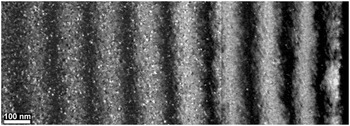
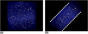
For the purpose of model information and validation, Li et al. coupled in situ TEM irradiation with electron tomography to characterize defect distributions in ion-irradiated Mo as a function of particle energy, dose, and film thickness. Reference Xu, Wirth, Li and Kirk19,Reference Li, Kirk, Baldo, Xu and Wirth30 The application of electron tomography enabled quantification of the impact of the proximity of the free surfaces on the defect population. The samples were irradiated to different ion doses in situ at the intermediate voltage electron microscope facility in Argonne National Laboratory with 1 MeV Kr ions at a temperature of 353 K. The foil thickness was estimated using the thickness fringes method. Reference Edington62 It should be noted that this method of estimating the foil thickness has an error associated with it that is dependent on the diffraction vector used, the accuracy of excitation error measurements, and uncertainty in determining the thickness fringe peaks. Reference Fultz and Howe63 An example of the observed change in the damage with increasing foil thickness can be seen in Fig. 1. Li et al. found that the free surfaces act as sinks to irradiation-induced defects, resulting in a linear dependence of the areal defect density on the foil thickness. Defect densities surrounding a grain boundary were also investigated and showed a similar sink-effect, though not as strong as at the free surfaces. Electron tomography was applied to a 110-nm thick region of the Mo sample irradiated to 5 × 10¹² ions/cm2 to characterize the through-thickness defect distribution. At this thickness, it is expected that the majority of the ions will pass through the foil, with approximately 7% of the total remaining embedded in it. In the reconstructed tomogram, it was found that the defect density decreased as the foil surface was approached. A 10 nm-thick denuded zone existed at both foil surfaces from which all visible irradiation-induced defects had escaped (see Fig. 2 for views of the reconstructed tomogram). This result is in contrast with those from the computer simulations of Stoller that showed larger vacancy clusters existing near the surfaces. Reference Stoller53 However, it should be noted that the simulations were conducted at 100 K in Fe while the experiments were conducted nominally at 353 K in Mo, changing the kinetics of the interaction. Li et al. reported that the experimentally measured defect distribution was asymmetric, with a higher defect density at the exit surface of the foil. This agreed well with expected stopping and range of ions in matter (SRIM) damage profiles.
Composite dark-field image showing increasing defect distribution with increasing thickness (from right to left) in Mo. The sample was irradiated in situ to 5 × 10¹² ions/cm2 with 1 MeV Kr ions (image reproduced with permission from Ref. Reference Xu, Wirth, Li and Kirk19).

Front (a) and profile (b) views of a tomogram showing defect distribution in an irradiated Mo sample. Image is false-colored with irradiation-induced defects highlighted in yellow. Free surfaces are indicated in (b) by dotted line. Image modified from supplementary video in Ref. Reference Li, Kirk, Baldo, Xu and Wirth30.

Li et al. compared the defect depth distributions obtained experimentally with computer simulations in which the irradiation and environmental conditions matched those used in the experiments (see Refs. Reference Li, Kirk, Baldo, Xu and Wirth30 and Reference Xu, Wirth, Li and Kirk64 for details on the simulation technique). Despite challenges in quantitatively comparing the results, such as estimating the population of ‘invisible’ defects, those that are in a g·b = 0 condition, the experiments and simulations agreed to within an order of magnitude when comparing variations in defect density with foil thickness. Encouragingly, both simulation and experiment showed a similar denuded zone at the foil surfaces, although in the simulations no asymmetry in the defect distribution near the two surfaces was found. This was highlighted as an area of further research. This initial work in modeling and characterizing irradiation damage in thin films, where results of computer simulations can be verified via direct observation in the TEM, was considered important as it establishes the fidelity of the computational approach before applying it to bulk materials.
IV. SINGLE DEFECT INTERACTIONS
Irradiation-induced defects capable of interacting with dislocations appear in a number of forms. Here, we focus on the interaction of dislocations with stacking-fault tetrahedra, which are three-dimensional vacancy defects. This form of irradiation damage is most common in low stacking-fault energy materials and occurs as vacancies agglomerate postirradiation into a low-energy configuration. Reference Wirth, Bulatov and De La Rubia65–Reference Silcox and Hirsch67 As the interaction of dislocations with these defects often leads to flow localization and channel formation, understanding the governing interaction mechanisms is necessary. Reference Dlaz de la Rubia, Zhib, Khraishi, Wirth, Victoria and Caturia68–Reference Farrell, Byun and Hashimoto70
Multiple experimental studies exist involving in situ TEM deformation on dislocation interactions with stacking-fault tetrahedra and Frank loops. Reference Zinkle and Matsukawa71–Reference Schaublin, Yao, Spatig and Victoria73 Zinkle and Matsukawa noted the ability of dislocations to annihilate stacking-fault tetrahedra in Au; here the tetrahedra were created by quenching in a population of vacancies rather than by irradiation. Reference Zinkle and Matsukawa71 The observed interactions resulted in superjogs forming on the glissile dislocations, creating a barrier to further glide. In observing dislocation interactions with stacking-fault tetrahedra and Frank loops in rapidly quenched Cu and Au, Robach et al. showed that the end result of a dislocation interaction with a tetrahedron could be annihilation, shearing, or conversion into new defects such as dislocation loops or truncated tetrahedra. Reference Robertson, Robach, Lee and Wirth74 They also showed that a single dislocation interaction was often insufficient to fully annihilate a stacking-fault tetrahedron. Schaublin et al. investigated the barrier strength of stacking-fault tetrahedra to dislocation glide using in situ TEM deformation of proton-irradiated copper. Reference Schaublin, Yao, Spatig and Victoria73 By measuring the curvature of the dislocations immediately prior to breaking away from being pinned at a tetrahedron, the average stress needed to overcome the obstacle was found to be approximately 100 MPa, significantly higher than the critically resolved shear strength of pure Cu, which is under 1 MPa. Reference Wadhwa and Dhaliwal75 Briceno et al. also investigated the interaction of dislocations with stacking-fault tetrahedra via in situ TEM deformation in quenched Au. Reference Briceño, Kacher and Robertson76 They tracked the motion of a single screw dislocation as it propagated through and interacted with a field of stacking-fault tetrahedra. This experiment eliminated the influence of such variables as external stress state and dislocation type on the resulting interaction. They reported that the interaction depended on the location and position of the slip plane intersection with the tetrahedron, i.e., on the face or edge and the distance from the vertex. Upon encountering the edge of a stacking-fault tetrahedron, the dislocation was pinned momentarily before cross-slipping and bypassing the obstacle. In contrast, when the dislocation intersected the face of a tetrahedron, the result was either partial or complete annihilation of the tetrahedron. In the case of partial annihilation, a smaller tetrahedron was left after the interaction. As all variables remained equal, the different outcomes were attributed to the location on the face of the tetrahedron intersected by the slip plane of the dislocation. Intersecting closer to the vertex resulted in partial annihilation. A difference in the reaction time was also noted. The cross-slip process required tens of seconds to complete whereas the annihilation occurred in a fraction of a second, leading to the conclusion that cross-slip interactions were the rate-limiting step during deformation.
Osetsky et al. have simulated the interactions of dislocations with stacking-fault tetrahedra using a variety of test temperatures, strain rates, and geometries to explain differences seen in experimental results. Reference Osetsky, Matsukawa, Stoller and Zinkle77–Reference Osetsky, Stoller, Rodney and Bacon79 For both edge and screw dislocations interacting with a stacking-fault tetrahedron, they observed that if the dislocation intersects the tetrahedron near the vertex, no lasting damage occurred. The vertex shifted a single Burgers vector but quickly recovered. This interaction changed when the glide plane intersected near the base of the tetrahedron. Edge dislocations caused the formation of a ledge on the tetrahedron, which, after the intersection of multiple dislocations, could result in the tetrahedron shearing completely into two separate defects. Gliding screw dislocations resulted in the unfaulting of the tetrahedron, leaving behind a much smaller tetrahedron. Depending on the proximity of the free surface, the absorbed vacancies either formed a superjog on the dislocation or escaped through the free surface, allowing further unimpeded glide of the screw dislocations. Similar to the experimental observations, the simulations show that a single dislocation interaction with a stacking-fault tetrahedron is often insufficient for complete annihilation. Rather the tetrahedra are either sheared or truncated. The strength of these interactions, or the applied stress needed for the dislocations to overcome the tetrahedra, varied between 80 and 180 MPa, similar to the values seen experimentally. Reference Schaublin, Yao, Spatig and Victoria73
Wirth et al. similarly used atomistic simulations to investigate the interactions of dislocations with stacking-fault tetrahedra. Reference Wirth, Bulatov and De La Diaz Rubia80 In simulating edge dislocations interacting with a perfect stacking-fault tetrahedron, they noted that the tetrahedron acted as a hard obstacle to dislocation motion and that the intersecting edge dislocations sheared but did not annihilate it. Even after the intersection of five dislocations with a single tetrahedron, the tetrahedron remained largely intact. Replacing the perfect tetrahedron with overlapping truncated tetrahedra resulted in annihilation of the tetrahedra with the vacancies absorbed onto the dislocation. A consequence of this interaction is that a superjog forms on the dislocation, which can render it sessile.
In comparing simulations to experiments, it is seen that the same variety of interactions occur: Shearing of a stacking-fault tetrahedron and partial and complete annihilation. They are also similar in that both show that multiple dislocations can intersect a single stacking-fault tetrahedron without annihilating it. However, more detailed comparisons remain difficult due to resolution limitations in electron microscopy. Specifically, the need for high-resolution three-dimensional characterization during in situ TEM deformation remains a significant challenge due to the relatively short time over which these interactions occur. This higher resolution is necessary to accurately measure geometrical details such as the location of the intersection of the glide plane with the tetrahedron as well as to characterize the morphological changes of the tetrahedron caused by intersecting dislocations.
V. DEFORMATION CHANNEL FORMATION
A distinctive feature of deformed irradiated materials is the prevalence of localized flow into deformation channels. Reference Sharp6,Reference Eyre and Bartlett8,Reference Dlaz de la Rubia, Zhib, Khraishi, Wirth, Victoria and Caturia68–Reference Farrell, Byun and Hashimoto70 These channels form as dislocations propagate through the matrix and interact with existing irradiation-induced defects. As a channel is formed in the matrix, a path of lower defect density is established in which the majority of the plasticity is concentrated. Reference Dlaz de la Rubia, Zhib, Khraishi, Wirth, Victoria and Caturia68 The formation of these channels is difficult to simulate computationally as it involves the interactions of hundreds of defects over timescales unobtainable with atomistic simulations, though channels have been successfully produced computationally using dislocation dynamics simulations informed by atomistic modeling. Reference Dlaz de la Rubia, Zhib, Khraishi, Wirth, Victoria and Caturia68,Reference Khraishi, Zbib, De La Rubia and Victoria69,Reference Ghoniem, Tong, Huang, Singh and Wen81,Reference Ghoniem, Tong, Singh and Sun82 Questions remain on the influence of irradiation-induced defects on glissile dislocation behavior, the factors determining the width of deformation channels, the evolution of the structure of the channels, and the interaction of the channels with other defects such as grain boundaries.
In situ TEM ion irradiation has been coupled with straining to explore the effects of irradiation on dislocation behavior and the process by which deformation channels are formed. Robach et al. Reference Robach, Robertson, Wirth and Arsenlis72 and later Briceno et al. Reference Briceno, Fenske, Dadfarnia, Sofronis and Robertson25 investigated the effect of irradiation-induced defects on the mobility of dislocations. Briceno et al. began their experiments by straining unirradiated stainless steel samples in situ in the TEM. Once dislocation activity was observed, the tension on the sample was relaxed, removing the driving force for further dislocation activity. The sample was then irradiated without removing it from the TEM using 1 MeV Kr ions to a dose of approximately 3 × 10¹⁷ ions/m2. Strain was again applied and the same dislocations were observed. The previously glissile dislocations were pinned by the irradiation-induced defects, demonstrating that the irradiation-induced damage acted as barriers to dislocation motion and that higher shear stresses were now needed to move these dislocations.
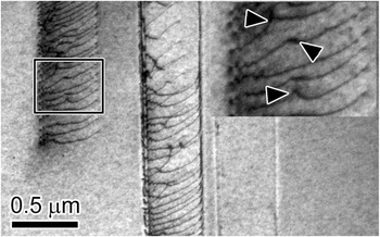
Further straining of these samples caused new dislocations to nucleate and propagate through the matrix. These dislocations nucleated either at grain boundary sources or from cracks emanating from the edges of the sample. Interestingly, the dislocations nucleating at the grain boundaries emerged from a volume of material rather than a single point, which gives the channel a natural width that is equal to the projected area of the source width on the slip plane. The irradiation-induced defects, which were assumed to be Frank loops, acted as barriers to dislocation motion, resulting in the dislocations moving in short, jerky steps. This led to higher than usual dislocation densities in grain interiors, culminating in dislocation pileups forming against invisible barriers. This is demonstrated in Fig. 3 in which a dense dislocation pileup, formed during in situ TEM straining of an irradiated stainless steel sample, is highlighted. Kinks on the dislocations, suggesting interactions with individual irradiation defects, are highlighted in the inset of Fig. 3, suggesting that irradiation-induced defects remain in the deformation channel after the passage of multiple dislocations.
Dislocation pileup formed in grain interior during in situ TEM straining of an ion-irradiated stainless steel sample. Arrowheads in the inset indicate regions where dislocations are interacting with irradiation-induced defects. Image modified with permission from Ref. Reference Kacher, Liu and Robertson21.

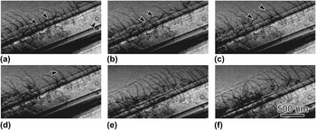
Although the propagating dislocations appeared to annihilate the majority of the irradiation-induced defects, significant levels of dislocation debris remained in the channel interiors. Glissile dislocations interacting with the remaining dislocation debris resulted in cross-slip interactions, leading to the development of complex dislocation configurations lining the channel boundaries. Figure 4 shows an example of a channel formed during in situ TEM deformation of an irradiated stainless steel sample. Dislocation debris, such as the loop indicated in Fig. 4(a), is still present. This loop was presumably formed from a pinch-off reaction caused by a dislocation interacting with an irradiation-induced defect and not directly from the irradiation itself. The channel boundaries appear to be composed of dense tangles of dislocations. Video taken during straining of the sample shows that these channel walls can act as nucleation sites for dislocation multiplication. A single dislocation in the form of a half loop emerging from the channel boundary and its motion is followed by arrowheads in Figs. 4(a)–4(d). This dislocation cross-slips from the channel and continues to glide through the matrix, effectively increasing the width of the deformation channel.
Dislocation half-loop emerging from defect free channel boundary during in situ TEM straining of an irradiated stainless steel sample. The half loop is indicated by arrowheads. A dislocation loop present in the channel interior is also indicated by an arrowhead in (a). Snapshot times are (a) 1.4, (b) 3.8, (c) 23.4, (d) 23.9, (e) 89.5, and (f) 118.3 s. Image is modified from Ref. Reference Kacher, Liu and Robertson21.

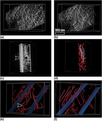
To reveal the three-dimensional structure within the deformation channel, Kacher et al. used the electron tomography technique as applied to dislocation structures. Reference Liu, House, Kacher, Tanaka, Higashida and Robertson24 They extracted a select volume from the electron transparent region of the straining sample by using focused-ion beam (FIB) machining. Reference Kacher, Liu and Robertson21 Loading the extracted volume on a double-tilt holder enabled them to acquire images of the same area every degree over an angular range of 56° while maintaining the same diffraction-contrast condition. A tomogram was then reconstructed from the aligned image series using a weighted-back projection algorithm. The small angular range used produced a low-resolution tomogram, which resulted in the dislocation images being elongated in specific viewing directions. However, by using diffraction contrast theory as well as using the tomogram as a template, a three-dimensional model of the dislocation structure was created. Select views of the tomogram and dislocation model constructed from the tomogram are shown in Fig. 5. In the tomogram, the dislocations appear as white lines; i.e., they are opposite of the bright-field images. Also apparent in the tomogram is a high density of small white dots. This is the ion damage produced by the FIB machining. Rotating the tomogram to a different viewing direction reveals the extent of the FIB damage; the layer boundary is marked by arrowheads in Fig. 5(c). In the three-dimensional model [Figs. 5(d)–5(f)], the image boundary was moved beneath the ion-damage layer. The model shows the confinement of the dislocations to the channel, although the dislocations have a complex line direction, which is unexpected if this channel had become an easy glide path. The arrowhead in Fig. 5(e) indicates a dislocation that has cross-slipped to overcome an invisible barrier. The dislocation wall bounding the channel is comprised of long straight parallel dislocations that reside on parallel planes through the foil thickness [Fig. 5(d)]. Other dislocations with glide paths that intersect this wall of dislocations would be blocked, which would establish the conditions for forming a dislocating source from within the dislocation wall. This provides an explanation for the dynamic observations that showed the walls serving as dislocation sources.
(a–c) Views of a reconstructed tomogram of a deformation channel. FIB-induced damage layer is indicated in (c). Dotted white lines indicate foil surfaces. (d–f) Three-dimensional dislocation model constructed from tomogram reconstruction. The approximate location of channel boundaries is indicated by blue planes. Elongated dislocations lining the channel are highlighted in blue in (d). A helical shaped dislocation is indicated by an arrowhead in (e). Image is modified with permission from Ref. Reference Kacher, Liu and Robertson21.

Due to the length scales involved, the full evolution of a deformation channel cannot be simulated using atomistic methods. Instead, dislocation dynamics, informed by experiment and molecular dynamics modeling, have been used to simulate the formation and evolution of defect free channels and strain localization in irradiated materials. Reference Dlaz de la Rubia, Zhib, Khraishi, Wirth, Victoria and Caturia68,Reference Khraishi, Zbib, De La Rubia and Victoria69,Reference Ghoniem, Tong, Huang, Singh and Wen81,Reference Ghoniem, Tong, Singh and Sun82 A primary feature in these simulations that can be compared to results obtained via TEM is the mechanism determining the channel width and growth. Ghoniem et al. reported that the channel width was established through dislocation climb mechanisms. Reference Ghoniem, Tong, Huang, Singh and Wen81,Reference Ghoniem, Tong, Singh and Sun82 As dislocations propagated through the irradiation-hardened matrix and absorbed stacking-fault tetrahedra and irradiation-induced loops, excess vacancies were incorporated into the glissile dislocation, resulting in climb. As such, the size of the defects was considered an important variable as larger defects contained more vacancies. Diaz de la Rubia and coworkers similarly used dislocation dynamics to model channel formation and strain localization, though they came to a different conclusion. Reference Dlaz de la Rubia, Zhib, Khraishi, Wirth, Victoria and Caturia68,Reference Khraishi, Zbib, De La Rubia and Victoria69 They found that dislocation interactions with the irradiation-induced defects resulted in dislocation cross-slip to avoid the obstacles. As the shear stress encouraged dislocation glide in the original glide direction, double cross-slip would take place. Each double cross-slip event expanded the width of the channel boundaries and created sources for additional dislocation generation. The channel width was ultimately limited by the formation of dipoles that exerted a back stress on the expanding dislocations. Both simulations relied on a simulated Frank–Read source within the simulation cell to generate the dislocations responsible for initiating the deformation channel. The activation of such a source is inconsistent with the experimental observations.
In comparing the simulations with the in situ TEM deformation experiments, it was seen that double cross-slip was a prominent feature, lending support for the cross-slip mechanism of channel widening. However, the origin of the cross-slip event was shown experimentally to be driven by more than just the interaction with the original defect. Cross-slip was triggered to overcome obstacles within the channel following its formation; this mechanism was not captured in the simulation. Simulations by both groups showed elongated dislocations lining the channel boundaries, though the mechanism for their generation, cross-slip as opposed to dislocation climb, varied significantly. Experimentally, it is seen that the dislocations along the edges of the channels form via cross-slip events. Additionally, and in contrast to the experimental results, neither simulation considered the volume from which dislocations nucleated as an important variable determining the width of the channels.
VI. DEFORMATION CHANNEL INTERACTIONS WITH GRAIN BOUNDARIES
Localized deformation, specifically deformation channel interactions with grain boundaries, has been suggested to be important for the mechanical properties of irradiated metallic alloys and as a key factor in explaining irradiation assisted stress corrosion cracking. Reference Was and Bruemmer9,Reference West, McMurtrey, Zhijie and Was10,Reference McMurtrey, Cui, Robertson, Farkas and Was83,Reference McMurtrey, Was, Patrick and Farkas84 Cracking of irradiated materials in corrosive environments has been correlated to the inclination of the grain boundary normal with respect to the loading direction and to the misorientation of the grain boundary, with random high angle grain boundaries being the most susceptible. Reference West, McMurtrey, Zhijie and Was10,Reference McMurtrey, Was, Patrick and Farkas84 However, the mechanism of localized dislocation interactions with grain boundaries in irradiated metals is just beginning to be explored.
In situ TEM deformation facilitates the comparison between the dislocation interactions with the grain boundaries and slip transfer mechanisms in irradiated and unirradiated materials. An advantage of conducting deformation experiments in situ in the TEM is that it allows the full evolution of an interaction to be observed, including the order in which events occur. This information is vital in determining the dominant mechanisms responsible for slip transfer. In unirradiated metals, the early stages of the interaction of dislocations with grain boundaries have been studied extensively. Reference Kacher and Robertson16,Reference Lee, Robertson and Birnbaum85,Reference Bieler, Eisenlohr, Roters, Kumar, Mason, Crimp and Raabe86 These studies have shown that dislocation pile-ups can form against grain boundaries and that dislocations can be incorporated into the grain boundary. The outgoing slip system is activated by the grain boundary and is enabled by the local stress state associated with the pile-up of incoming dislocations. This generally results in dislocations propagating quickly from the nucleation site at the boundary, suggesting that dislocation nucleation, not propagation, is the rate-limiting step. Two dominant criteria have been established that dictate which system will be activated by the grain boundary, these are Reference Lee, Robertson and Birnbaum85 :
-
(i) The magnitude of the Burgers vector of the dislocations left at the grain boundary |b r| by the transmission event should be minimized; i.e., b r = b in − b out, where b in and b out are the Burgers vector of the incoming and outgoing dislocations, respectively.
-
(ii) The resolved shear stress acting on the possible slip systems in the adjoining grain should be maximized.
Of these, the slip system activated by the grain boundary in response to an impinging slip system is determined primarily by the first criterion in unirradiated materials. Reference Kacher and Robertson16,Reference Lee, Robertson and Birnbaum87–Reference Sangid, Ezaz, Sehitoglu and Robertson89 That is, the dominant system activated by the grain boundary will minimize the strain energy density accumulation in the grain boundary. The second criterion is important in that the emitted slip system must experience sufficient shear stress to ensure dislocation motion away from the nucleation site and into the grain.
The mechanism of slip transfer in irradiated metals is not well understood, compared to that in unirradiated metals. The recent work by Cui et al. focused on quantitative analysis of dislocation interactions with grain boundaries during in situ TEM deformation of ion-irradiated stainless steel samples.
Reference Cui, Kacher, McMurtrey, Was and Robertson90,Reference Cui, McMurtrey, Was and Robertson91
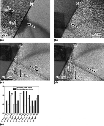
An example of slip transmission in an irradiated metal is shown in Fig. 6, which shows the interaction of glissile screw dislocations,
 ${a \mathord{\left/ {\vphantom {a 2}} \right. \kern-\nulldelimiterspace} 2}\left[ {011} \right]_{{\rm{in}}} \left( {1\bar 11} \right)_{{\rm{in}}}$
, with a [101]/110° grain boundary in a 1 dpa Kr+ irradiated 304 stainless steel. Dislocations are seen to pileup at the grain boundary, resulting in a buildup of elastic strain in the neighboring grain but no slip transmission. The initial dislocation response of the grain boundary was the back-emission of a dislocation system originating at the intersection of the grain boundary and the incoming dislocation system, labeled 1c
in in Fig. 6(a). Further straining resulted in the emission of a limited number of dislocations that extended a short distance into the neighboring grain. As more dislocations piled up at the grain boundary, two new systems activated labeled 1a
out,
 ${a \mathord{\left/ {\vphantom {a 2}} \right. \kern-\nulldelimiterspace} 2}\left[ {0\bar 11} \right]_{{\rm{out}}} \left( {111} \right)_{{\rm{out}}}$
, and 1b
out,
 ${a \mathord{\left/ {\vphantom {a 2}} \right. \kern-\nulldelimiterspace} 2}\left[ {0\bar 11} \right]_{{\rm{out}}} \left( {\bar 111} \right)_{{\rm{out}}}$
and the magnitude of the local stress increased [Figs. 6(c) and 6(d)]. These systems operated concurrently until an avalanche of dislocations emitted from the boundary.
Bright-field electron micrographs showing the outcome of the interaction of screw dislocations against a [101]/110° grain boundary in 1 dpa Kr+ irradiated 304 stainless steel (Ref. Reference Silcox and Hirsch67). (a) Formation of the dislocation pile-up. Black arrow indicates the strain accommodation in the form of an elastic distortion emanating from the grain boundary. (b) Outgoing dislocations (arrowed) nucleated in the adjoining grain but these did not propagate far from the grain boundary and their activity was limited. (c) Slip transmission. (d) “Avalanche” of dislocations was emitted from the grain boundary. (e) Burgers vector of the residual grain boundary dislocation left after the interaction for each possible emitted slip system as well as the normalized resolved shear stress acting on the systems. Activated systems are labeled as 1a and 1b.

Comparing the shear stress acting on systems 1a out and 1b out from the dislocations piled up at the boundary to all available dislocation systems, it was found that systems 1a out and 1b out both experience the maximum stress [Fig. 6(e)]. In addition, both systems generate grain boundary dislocations with the smallest Burgers vector. From this and other experiments, it was found that the transmission criteria for slip through a grain boundary developed for unirradiated face-centered cubic (FCC) metals are applicable in irradiated FCC systems with the caveat that the resolved shear stress increases in importance. That is, slip transmission is governed by the magnitude of the Burgers vector of the dislocations or the increase in the strain energy density generated in the grain boundary. However, in contrast to unirradiated FCC metals, for these dislocations to be released from the grain boundary source the magnitude of the resolved shear stress experienced by that slip system must be of sufficient magnitude to propagate the dislocations through the obstacle field. This effectively increases the required shear stress for the activation of a dislocation system. McMurtrey et al., based on macroscale experiments, have similarly concluded that the shear stress is a critical factor in differentiating between the responses of the grain boundary. Reference McMurtrey, Cui, Robertson, Farkas and Was83
VII. FUTURE DIRECTIONS
In situ TEM irradiation and deformation experiments coupled with computer simulations are powerful techniques in elucidating the evolution of irradiation damage as well as its effect on dislocation behavior. The addition of electron tomography also marks a significant achievement as it overcomes shortcomings associated with the two-dimensional nature of images acquired in the electron microscope and allows more direct comparison to simulation. This study has highlighted successful combinations of simulations and experiments in areas such as defect distribution during ion-irradiation of thin films and dislocations interacting with isolated defects. There are, however, significant barriers to overcome for a more successful integration of simulation and experiment from both the experimental and modeling approach. This includes the ability to obtain higher resolution tomograms of dislocation interactions during in situ TEM deformation experiments, allowing the experimental validation and clarification of dislocation interactions with irradiation-induced defects. Currently, small jogs and kinks, expected to form during interactions with stacking-fault tetrahedra, or the ledges formed on the tetrahedra from interactions with gliding dislocations are below the resolution of TEM characterization in three dimensions. It is expected that further concerted effort to combine experimental and simulation efforts such that the results from each can be directly compared will significantly advance the understanding of irradiation damage effects in materials.
ACKNOWLEDGMENTS
This work was supported financially by the US Department of Energy under Award No. DE-FG02-08ER46525 (BC and IMR) and the US Department of Energy Office of Basic Energy Sciences under Award No. DEFG-02-07ER46443 (JK and IMR).