NOMENCLATURE
- Cd
drag coefficient
- CL, Cl
lift coefficient
- C Lmax
maximum lift coefficient
- Cm
pitching moment coefficient
- Cµ
blowing momentum coefficient
- Cnβ
directional stability
- Cp
pressure coefficient
- Hi
incompressible boundary layer shape factor
- M
free stream Mach number
- N
instability amplification factor
- Pi
free stream total pressure
- Q
second invariant of the velocity gradient tensor (used for vorticesvisualisation)
- S
abscissa along a streamline
- V
free-stream velocity
- α
incidence
- β
sideslip
- AIP
aerodynamic interface plane
- 3AF/AAAF
Association Aéronautique Astronautique de France
- AoA
angle-of-attack
- CDI
circumferential distortion intensity
- CFD
computational fluid dynamics
- CNRS
French National Centre for Scientific Research
- DES
detached eddy simulation
- DGA
Délégation Générale pour l'Armement
- DSTL
Defence Science and Technology Laboratory
- EARSM
explicit algebraic Reynolds stress model
- HLFC
hybrid laminar flow control
- HTP
horizontal tail plane
- IR
infrared
- LO
low observability
- NLF
natural laminar flow
- OASPL
overall sound pressure level
- ONERA
Office National d'Etudes et Recherches Aérospatiales
- RANS
Reynolds-averaged Navier-Stokes
- RDI
radial distortion intensity
- S2MA
S2 Modane-Avrieux WT
- SST
shear stress tensor
- UCAV
unmanned or uninhabited combat aerial vehicle
- VG
vortex generator
- WT
wind tunnel
Symbols
Abbreviations
1.0 INTRODUCTION
Flow control is not a new research topic. Some of the activities on flow control in France began just after the Second World War with Philippe Poisson-Quinton from the Office National d'Etudes et Recherches Aérospatiales (ONERA). Since the end of the 1940s, he worked on boundary-layer control(Reference Rebuffet and Poisson-Quinton1) and also on circulation control(Reference Malavard, Poisson-Quinton and Jousserandot2) considering steady blowing and suction on configurations of wings with flaps. In his publication from 1948(Reference Poisson-Quinton3), he defined the blowing momentum coefficient Cµ, which is still massively used to quantify the energy cost of blowing flow control.
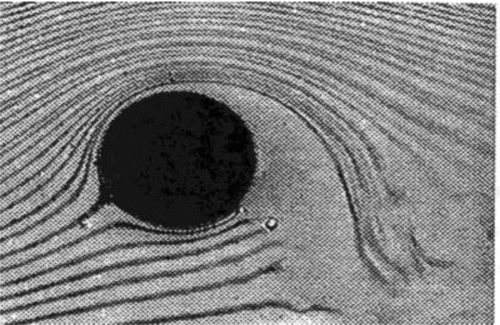
An example of flow control application in other domains than aeronautics is the turbo sail, which was developed in 1982 by Malavard and Charrier for Commandant Cousteau and tested on two ships: Moulin à Vent and Alcyone. The turbo sail generated lateral lift on a mast with an elliptic section, circulation improvement being obtained with steady suction for boundary layer re-attachment and lift increase by a small flap, as shown in the water tunnel experiment from ONERA(Reference Werle4) (see Fig. 1). Some renewal occurred in the early 1990s in the United States (with scientists like Wygnanski and Seifert(Reference Seifert, Bachar, Koss, Wygnanski and Shepshelovich5) or Glezer and Amitay(Reference Glezer and Amitay6)) with new ideas based on unsteady ways of actuation, such as pulsed jets or synthetic jets, located at the most sensitive points of the flow and able to re-attach separated flows at a reduced energy cost as compared to classical means (see Fig. 2).
Water-tunnel visualisations at ONERA of the turbo sail aerofoil (a) without and (b) with flow control.

Flow separation control on a cylinder using synthetic jet actuation(Reference Glezer and Amitay6).
In France, Pierre Perrier from Dassault Aviation, who was well aware of these new research orientations, anticipated the potentialities of such flow controls(Reference Perrier, GAD-EL-HAK, POLLARD and BONNET (Eds)7). The idea was to inject the right perturbation at the right place to benefit from the amplification effect given by the flow. Since the mid 1990s, he initiated a lot of research activities in this domain at ONERA, in the French National Centre for Scientific Research (CNRS) laboratories and in universities (e.g. Ecole Centrale de Lyon, LEA Poitiers, IMFT Toulouse, LPMO Besançon, LML Lille, IEMN Lille, Ladhyx, IRPHE Marseille and ENSICA Toulouse). He did not spare his time and energy to successfully federate the scientific community around the multidisciplinary challenges of active fluid mechanics. In most of the topics, fundamental research was performed by CNRS laboratories doing parametric studies. It helped in defining more applied configurations to be studied at ONERA. Dassault Aviation was in charge of the flow control design and the coordination of the projects.
Flow control was studied both for military and civil aircraft applications (see Figs 3 and 4). The first potential applications concerned the improvement of combat aircraft manoeuvrability and its ability to experience high angles-of-attack (AoAs), as well as the regularisation of the global aerodynamic forces and moments. The contributing subjects were the control of forebody vortices in order to control the yawing moment at a high AoA, the control of wing vortex breakdown in order to complement the effect of the classical control surfaces, the control of the flow in the air intake and air duct in order to improve its efficiency at a very high AoA, and the thrust vector control in order to vectorise the thrust without any moveable nozzle parts. Another potential centre of interest was plume-mixing enhancement for stealth purpose.
Potential applications of flow control (a) on a combat aircraft and (b) and on a UCAV.
Potential applications of flow control on a business jet.
For an un-manned or un-inhabited combat aerial vehicle (UCAV) platform, potential applications of flow control were aimed to help in the design when doing the trade-off between aerodynamics and low observability (LO). Among them we can list wing stability improvement in low-speed high-lift conditions, separation control in the highly bent air duct for LO purpose, vibration control in the open weapon bay for store release, fluidic control surfaces and fluidic thrust vector control which may help during flight phases with high requirements on LO.
For a business jet, potential applications are related to flow separation control on the high-lift configuration in order to improve the lift-to-drag ratio during take-off and the maximum lift coefficient during landing, to laminarity control to reduce friction drag during cruise, to the extension of buffet limits of the wing and to flow separation control at the rear fuselage in cruise conditions, as well as to the reduction of engine noise by increasing the plume mixing.
First, a set of examples illustrating different types of flow control will be presented, the most studied one being separation control, then the control of free shear layers, circulation control and laminarity control. In a second part (see section 6.0), the integration challenges of these technologies will be addressed.
2.0 EXAMPLES OF FLOW SEPARATION CONTROL
For flow separation control, we will consider four examples: the first one is related combat aircraft manoeuvres, the following two are for UCAV and the last one addresses buffet for a business jet.
2.1 Control of forebody vortices
The first example corresponds to the control of forebody vortices. It is the best illustration of the amplification of a small perturbation by the flow. The associated flow problem will be described.
On a fighter aircraft with a conic forebody, flow separates on the sides above a given AoA creating two vortices. Above an AoA of 45° (see Fig. 5), a vortex asymmetry dominates the flow creating a lateral force and an unpredictable yawing moment on the aircraft, since the asymmetry is dependent on the forebody tip-surface imperfections. Moreover, at high AoA, the fin becomes inactive since it is wrapped in a separated zone of the flow. This leads to a yaw instability.
Flow characteristics on a fighter aircraft with conical forebody at high AoA.
The idea of the flow control is to take advantage of the extreme flow sensitivity at the tip(Reference Courty and Van8,Reference Rosenblum, Courty and Van9) . By generating a calibrated asymmetry (side blowing, rotating micro-strake, etc.), one can trigger the vortex asymmetry on one side or another. The designed actuator, which is only a few centimetres long for flight conditions, is shown in Fig. 6(a). For axial blowing, only a mass flow of 1g/s is needed at full scale(Reference Courty10), which is quite negligible as compared to the engine mass flow. By achieving a duty cycle of 50% between port and starboard blowing, we bring symmetry to the average flow. For a different duty cycle, we get a new yaw control device with a linear effect of side force and yawing moment with the duty cycle (see Fig. 6(b)).
Flow control actuator and its effect on the forebody lateral force.
Comparison of yaw efficiency versus AoA on a generic fighter aircraft for a rudder deflection, a forebody strake and forebody blowing in natural transition and triggered transition modes.
When the efficiency of the rudder drops with AoA, the efficiency of the blowing increases and replaces it. A particular attention must be paid to the state of the forebody boundary layer. When it is laminar or turbulent (non-triggered case and triggered transition in the graph), a significant efficiency is obtained. In transitional mode, the efficiency drops. Therefore, the boundary-layer state has to be taken into account when using such a device.
2.2 Stability control in low-speed, high-lift conditions
Stability was one of the major contributions of Frederick William Lanchester to aerodynamics. In his book, Aerial Flight, published in 1907(Reference Lanchester11), he not only expressed the first comprehensive theory of lift and drag, but also addressed the stability issue, which was fundamental to aviation.
Stability issues limit the flight domain of UCAV wings in low-speed, high-lift conditions and have a direct impact on the approach speed. Trying to delay the longitudinal and directional instabilities using flow control may help compromise between cruise and low speed when designing the UCAV wing.
One example which illustrates the use of flow control for UCAV stability improvement was developed during a fruitful French/UK joint study involving industry (BAE Systems, QinetiQ, Dassault Aviation) and ONERA under the support of the Defence Science and Technology Laboratory (DSTL) and Délégation Générale pour l'Armement (DGA). The objective was to investigate the potential performance increase brought by flow control in approach conditions when designing the UCAV wing as a trade-off between low-speed and high-speed conditions. Figures 8 and 9 present the aerodynamic characterisation of one of these designs, which was performed in the Warton low-speed wind tunnel at BAE Systems. On such a configuration, the maximum usable CL is firstly limited, not by C Lmax, but by the pitch-up instability, which is associated to a whirlwind vortex on this class of wings. This vortex deviates the flow over the wing in the spanwise direction and promotes flow separation. A second limit in CL comes from the directional instability, which corresponds to the same flow phenomenon as pitch-up, but on the leeward wing only. In the case of this generic wing, the limiting value is related to the lateral behaviour.
Flow characterisation on a generic UCAV wing in BAE Systems Warton low-speed wind tunnel (LSWT).
Characterisation of longitudinal and directional stabilities on the generic UCAV wing.
Improvement of longitudinal and directional stabilities with fluidic flow control.
Oil flow visualisation close to the directional stability limit with fluidic flow control.
Several mechanical and fluidic devices were investigated using computational fluid dynamics (CFD) and wind-tunnel (WT) tests in order to delay or even remove flow separation. One of the best performing one was seen to be blowing through a slot in the leading-edge region, which allowed suppressing pitch-up (a pitch-down was observed), and delaying the directional instability by nearly 3° in α, thus leading to an improvement in max usable CL which is expressed in Fig. 10.
The wing and flow control design was based on Reynolds-averaged Navier-Stokes (RANS) CFD. Since the stability limits are linked to wide flow separated regions, a wide scattering of CFD results was experienced with respect to the instability prediction. As an example, for pitch-up on this wing (see Fig. 12(a)), the kω shear stress tensor (SST) model was the turbulence model which predicted flow topology the best, whereas the k-kl explicit algebraic Reynolds stress model (EARSM) better predicted the pitch-up break. Concerning the directional instability (see Fig. 12(b)), the k-kl EARSM computations were closer to the test results than kω SST, which created a wrong flow pattern on the windward wing. This last result was obtained by all the partners, independently from mesh refinement. This illustrates the difficulty to tackle the stability problems with a unique turbulence model. Depending on flow topologies, one model may be more appropriate than another.
RANS prediction of longitudinal and directional stabilities.
2.3 Flow separation control in a highly convoluted air duct
Another example, which illustrates flow separation control in the case of internal flows, corresponds to a second study which was performed within the frame of the France/UK collaboration in advanced aerodynamics and involved the same partners. This research topic supported by DSTL and DGA was dedicated to flow control in highly convoluted UCAV air ducts. A communication related to this subject has already been presented by Ian Whitmore from BAE Systems during the Royal Aeronautical Society Applied Aerodynamics Conference from July 2012 in Bristol(Reference Whitmore, Weatherhill, Stevens, Green, Vallee, Bourasseau and Massonnat12).
The associated context can be described as follows. The convolution is one of the design possibilities for an air duct. It contributes to the compactness of the UCAV propulsion system, to the optical hiding of the engine face and thus to some attenuation of radar cross-section (RCS). Due to the short duct length, the air duct presents higher curvatures which may generate flow separations and which are responsible for high levels of swirl and unsteadiness within the duct.
The air duct designer has to provide a level of flow quality at the aerodynamic interface plane (AIP) which is compatible with the engine manufacturer requirements. The metrics for it is mainly described by dynamic total pressure distortion and swirl. During testing the AIP flow quality and inhomogeneity are characterised by two components: the radial distortion intensity (RDI) and the circumferential distortion intensity (CDI). The engine's tolerance to dynamic total pressure is represented by a doghouse or igloo plot, which has to contain all the dynamic distortion vectors as in Fig. 13.
A typical doghouse plot for dynamic distortion compared to engine tolerance.
The design objective is to minimise the impact of flow separation bubbles. The main flow features which are observed in the clean duct (see Fig. 14) are the following: In relation to the first bend there is some bottom boundary-layer thickening (contributing to RDI in the outermost annulus) and also generating small lateral vortices on the sides. But the main contribution to unsteady flow corresponds to the 3D-horseshoe separation in the second bend roof, the consequence being a big separation bubble inducing swirl and circumferential distortion in the AIP.
Clean duct designed by Dassault Aviation.
This clean duct was characterised during tests at ONERA R4 Modane. The AIP was instrumented with a total pressure rake, which could be turned to get intermediate average values. It exhibits the same flow phenomena as those identified in the CFD (see Fig. 15(a)). Moreover, the testing gives access to the dynamic distortion plot (Fig. 15(b)) showing the cloud of instantaneous distortion points. Flow control technique was applied to improve the flow quality. Two regions were defined, where flow control could be applied: the one associated to the first bend and the one corresponding to the second bend.
Clean duct characterisation in the AIP at ONERA R4 Modane.
The flow control study was shared in two phases: the first one was dedicated to flow control using mechanical vortex generators (VGs) and the second one to the transposition to air jet VGs. During the first phase, Dassault Aviation optimised the VG's definition and arrangement, either to minimise the swirl or to minimise distortion. The CFD design was followed by the R4 testing: the main results were that VGs for swirl reduction (see Fig. 16) allowed dividing the maximum swirl by a factor of two and reducing CDI, whereas VGs for distortion reduction (see Fig. 17) gave some improvement both in RDI and CDI, even reducing maximum swirl by one fourth. The same design principles were transposed to air jet VGs a second time. The second testing phase corresponding to the air jets gave very promising results.
Effect of mechanical VGs designed for swirl reduction on average total pressure.
Effect of mechanical VGs designed for distortion reduction on average total pressure.
2.4 Buffet control
The last example for flow separation control is related to buffet control using mechanical VGs or air jet VGs to delay the buffet onset limit. Pneumatic VGs are preferable to mechanical ones since they have less drag penalty during the nominal cruise.
Some experimental tests had been performed by ONERA on an OAT15A wing in the T2 WT (see Fig. 18) showing that co-rotating mechanical VGs could be placed at a long distance from the shock location (15% of chord), while still being efficient. RANS computations were able to simulate the improvement brought by the VGs.
Effect of mechanical VGs on OAT15A wing for buffet onset delay.
A numerical parametric study was performed in 2003 for air jet VGs in order to prepare a future experimental test. These studies included several air jet VG locations, spacing, blowing velocities, pitch-and-tilt angles and injected mass flow on a generic business jet wing section at Mach 0.8 for a given local CL corresponding to buffet onset. An example of such RANS computation is given in Fig. 19, which shows the ability of the air jet VGs (with supersonic blowing jet) to suppress boundary-layer separation. This is confirmed by the significant reduction of the boundary-layer shape parameter Hi from 6 to 2.5 at the trailing edge and the modification of the Cp slope after the shock.
Effect of air jet VGs on boundary-layer shape factor and Cp plots in a generic business jet wing section.
We had to wait until 2010 to get an experimental validation of the efficiency of fluidic VGs for buffet control within the European Commission AVERT project (Aerodynamic Validation of Emission Reducing Technologies, coordinator Airbus Operations Ltd, Contract N° A5-CT-2006-030914)(Reference Dandois, Molton, Lepage, Geeraert, Brunet, Dor and Coustols13). These demonstration tests were financially supported by Airbus Operations Ltd, Airbus Operations SL, Alenia Aeronautica, Dassault Aviation, ONERA and the EU. This experimental activity was performed in ONERA S2 Modane WT (S2MA) on a half-wing configuration. Air jet VGs located at 15% of the chord were able to suppress the flow separation associated to buffet onset and to delay the buffet limit even better than mechanical VGs or trailing-edge devices (see Figs 20 and 21).
Oil flow visualisations at ONERA S2 Modane-Avrieux WT (S2MA) of the effect of air jet VGs to delay buffet onset.
Effect of air jet VGs, mechanical VGs and fluidic trailing-edge devices (FTED) on the buffet onset limit (ONERA S2MA WT test result).
3.0 CONTROL OF FREE SHEAR LAYERS
The next class of flow control is related to free shear layers, which can be found in engine plume or weapon bays.
To illustrate the flow control of a free shear layer, some other results coming from the French/UK collaboration on advanced aerodynamics will be considered. This third subject is related to the improvement of the aerodynamics of weapon bays in order to reduce vibrations. This research study involved BAE Systems, Dassault Aviation and ONERA and was supported by DSTL and DGA. Such a flow is characterised by its fully 3D aspect, its high turbulence level, its unsteadiness associated to the flow separation and the behaviour of the resulting shear layer. Due to all these flow characteristics, the most appropriate CFD method to simulate such a flow is detached eddy simulation (DES).
The associated flow physics can be recalled as follows. The overall dimensions of the cavity play a role on the detailed unsteady flow characteristics. The incoming fuselage boundary layer separates at the beginning of the cavity, generates a shear layer which develops according to the Kelvin-Helmhotz instability and interacts with the rear wall of the weapon bay. This interaction generates an acoustic wave which propagates upstream.
The overall interactions with the cavity geometry generate a self-sustained aeroacoustic mechanism. Some periodicity in pressure fluctuations leads to the acoustic Rossiter modes associated to specific frequencies.
Figure 22 illustrates the comparison of a non-controlled situation (Fig. 23(a)) and a controlled case with a flat spoiler (Fig. 23(b)). The main effect of the spoiler is to deflect the shear layer and thus to reduce its interaction with the cavity rear wall.
Instantaneous Q criterion in the symmetry plane (a) without and (b) with a spoiler at the front wall.
CFD characterisation of the cavity aerodynamics without and with flow control devices.
The study was dedicated to improve the aerodynamics of the weapon bay in a high transonic regime through the improvement of the cavity design and flow control devices. The investigated devices were either mechanical or fluidic. The parametric studies performed at Dassault Aviation corresponded to nearly 70 DES computations which were run during a three months period, which shows the considerable computational effort which was performed on the subject. Figure 23(a) shows some typical results coming from the numerical study. It is customary in cavity flow studies to report the unsteady pressure level on the cavity ceiling and walls as the overall sound-pressure level (OASPL) expressed in decibels. It represents the ratio of the unsteady pressure to the standard pressure for the minimum audible sound. This graph shows how the acoustics of the uncontrolled case is improved by some of the investigated devices, for which pressure fluctuations on the ceiling and rear wall are attenuated. Figure 23(b) shows how the devices interact with the shear layer and modify the interaction with the cavity ceiling.
A WT test campaign was performed at ONERA S1 Modane in order to test several of these flow control solutions. Among them a fluidic device was tested and confirmed the potential improvement which had been seen before with CFD (see Fig. 24(b)). The dynamic pressure reduction inside the cavity was observed, even for the lowest blowing mass flow values, and increasing this mass flow further led to a saturation of the effect. When compared to a mechanical solution, the use of a fluidic device solution could present the advantage of being effective even during the opening of the cavity doors.
Results of the effect of a fluidic device tested at ONERA S1MA.
These tests allowed performing the numerical validation of DES methods as compared to the experimental data. In Fig. 25 we present this comparison on one of the controlled test cases. It shows that the DES with a standard mesh (20 Million nodes) is sufficient to capture the unsteady pressure behaviour of the cavity. Refining the mesh isotropically (160 Million nodes) brings little improvement. There is still one measurement point showing some discrepancy, due to the fact that it is located in a high gradient region.
Comparison of OASPL between CFD and test results for a controlled case.
4.0 CIRCULATION CONTROL
The context of fluidic control surfaces was to be able to control the UCAV without moving conventional control surfaces during flight phases where LO is required. Potential candidates were fluidic aileron, fluidic flaps or spoilers and fluidic thrust vectoring.
An aileron is based on circulation control, and a natural means of doing that is to do the actuation at the trailing edge. It is why Dassault Aviation designed a fluidic aileron based on the Coanda effect, with some slot blowing close to the rounded trailing edge in order to be able to deflect the surrounding flow either downwards or upwards. This design was performed with fast computations based on 2D with sweep effect RANS (see Fig. 26(a)) and transposition to 3D. A proof-of-principle test was performed at ONERA Lille. Then, the pneumatic system was designed and integrated in the experimental validation aircraft (AVE) in order to test the effect of the blowing system at full scale in an F1 WT (see Fig. 26(b)). The outcome was a comparison of the fluidic aileron to a mechanical one, showing as much efficiency as a 30° deflected aileron (see Fig. 27(a)). Some flight tests of AVE took place in October and November 2008 in order to identify the fluidic aileron in flight (see Fig. 26(c)). Similar aileron efficiencies, as in WTs, were deduced from flight tests.
Several phases of the fluidic control surfaces study.
Efficiency of fluidic control surfaces versus blowing mass flow compared to mechanical control surfaces (WT test and CFD results).
A similar methodology was applied for yaw control surfaces based on differential flaps, either fluidic or mechanical. Here again, significant yawing moment efficiencies were obtained and confirmed during flight tests, fluidic scissors’ flaps being more efficient than the piano variant (see Fig. 27(b)). The next steps would be to test the platform control using control laws based on fluidic control surfaces and also to perform the transposition to cruise conditions.
5.0 LAMINARITY CONTROL
The last example concerns laminarity control. It is the very first type of flow control experienced at Dassault Aviation.
For purpose of transonic cruise drag reduction, postponing laminar-turbulent boundary-layer transition is an important issue which can be met by wing shape optimisation for low-sweep leading-edge angles (NLF or natural laminar flow), or coupled with localised suction for higher sweep-angle (hybrid laminar flow control or HLFC). Studies in these purposes have been undertaken by Dassault Aviation leading to flight test demonstrations (see Fig. 28):
• Falcon 50 with natural laminar fin (1985-1987)
• Falcon 50 with HLFC laminar glove (1987-1990) which allowed setting up suction for hybrid laminarity and assessing transition criteria in real flight conditions(Reference Bulgubure and Arnal14,Reference Courty, Bulgubure and Arnal15) .
• Falcon 900 with HLFC laminar glove (1993-1997) which demonstrated suction technology viability, leading-edge anti-contamination bump, set-up and validation of the computation tools (3D boundary layer and stability analysis).
Flight demonstrations of laminarity control on Falcon jets.
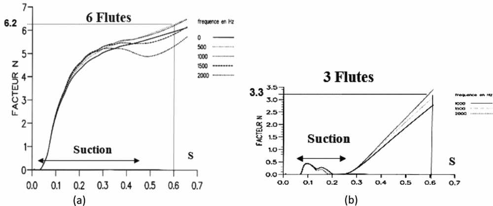
The laminarity control of a wing is a good illustration of the impact of numerical and theoretical progress, and thus, better knowledge of the underlying flow physics on the flow control efficiency. All this progress was achieved thanks to the efficient collaboration between Dassault Aviation and Daniel Arnal and his team from ONERA Toulouse. As an example, the linear stability code from ONERA(Reference Arnal16-Reference Arnal, Casalis and Houdeville19) computing the amplification N-factor had been used to design the HLFC suction system with six suction flutes (see Fig. 29). A complementary refined analysis from Daniel Arnal with a non-local stability code solving parabolised stability equations allowed for optimising the number and position of suction flutes (see Fig. 30). By concentrating the suction flutes in the region where the instabilities begin to grow, it is possible to dampen them drastically (i.e. the N-factor at abscissa 0.6 is divided by two, allowing a further extension of the laminar region).
Falcon 50 HLFC glove equipped with suction flutes.
N factor amplification with (a) initial and (b) optimised suction location and width.
More recently, Dassault Aviation has investigated extended natural laminarity on the wings within the European project Cleansky, in Smart Fixed Wing Aircraft Integrated Technology Demonstrator. The research leading to these results has received funding from the European Union's Seventh Framework Programme (FP7/2007-2013) for the Cleansky Joint Technology Initiative under grant agreement CSJU-GAM-SFWA-2008-001. In order to help for future flight tests and to gain confidence in terms of allowable roughness and waviness of the wing surface, as well as for being able to give acceptable manufacturing tolerances, some in-flight demonstrations have been recently performed on a Falcon 7X Horizontal Tail Plane. In-flight conditions and optimum horizontal tail plane (HTP) settings have been computed in order to show a sufficient laminar extension on the HTP upper side. An infrared (IR) camera was mounted on top of the vertical tail plane to obtain IR images of the HTP upper surface (see Fig. 31). Some calibrated steps have been glued on the HTP and their effect on transition has been measured in-flight in order to assess the critical heights of details leading or not leading to transition(Reference Courty, Tran and Petit20). The nature of instabilities, Tolmienn Schlichting or cross flow, has been characterised by computation(Reference Gross, Courty, Tran, Mallet, Arnal and Vermeersch21). Dassault Aviation is now contributing to the HLFC research effort with Airbus and European research centres within the European project, AFLoNext.
Flight tests of NLF on F7X HTP and example of data given by IR measurement. (a)(b)
6.0 INTEGRATION CHALLENGES OF FLOW CONTROL TECHNOLOGIES
After all these examples, one key point is related to the integration challenges associated to these technologies. In order to have them ready for an aircraft programme, we must increase the associated Technology Readiness Level so that it gets a sufficient maturity to be chosen. The first steps of the maturation process may be listed as follows:
• Concept definition and design
• Proof of principle
• Integrated design and WT assessment
• System development for flight tests and integration to a demonstration platform
• Flight tests of the technology
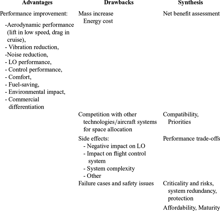
However, the most important thing is to be able, very early in a project, to know the technologies which are relevant to be considered. Therefore, it is mandatory for each of the flow control technologies to be able to draw a multi-disciplinary synthesis table, which will show all the foreseen aspects of the technology in relation to its integration aspects. It may help to make decisions about whether to choose the technology for a given programme.
Table 1 shows some idea of what could be such a table addressing advantages, drawbacks and questions to be answered. The advantages consist mostly in the quantification of performance improvement. The direct associated drawbacks are the mass increase and the energy cost which need to be taken into account in order to assess the consolidated net benefit.
Multi-disciplinary synthesis table for technology assessment with respect to potential application projects
Two other aspects which have to be considered concern, on one side, the side effects of the technology on other aircraft technologies and systems and the performance trade-offs to be considered. On the other side, we must consider the competition with other technologies and aircraft systems for space allocation, which raises questions about priorities and compatibility.
Another aspect is related to operational aspects and certification issues addressing failure cases and criticality of the technology. A project manager will always ask the question, “If it fails, do we lose the aircraft?” This leads to two options: either you try to get enough redundancies to keep the technology on board or you only retain non-critical technologies.
Then, there are also interrogations about the economic aspects (e.g. what is the associated cost?) and about maturity.
7.0 CONCLUDING REMARKS
During the last 25 years, a lot of progress has been performed on many subjects related to what was called “active fluid mechanics.” This progress would not have been possible at Dassault Aviation without the help of CNRS laboratories, ONERA, European Research centres, and the following industries: Snecma, BAE Systems, QinetiQ, Airbus and other European industrial partners. All this research was achieved thanks to the support and funding of DGA, DSTL, DGAC and European Union.
Industrial demonstrations, which are more concerned with robustness of the technologies, are sometimes far from the initial target of minimising the perturbation energy. There is still some place for fundamental research on the way to take advantage of flow instabilities. Moreover, closed-loop flow control may be a promising option in order to reduce the power consumption. The CNRS research network “GDR on Flow Separation Control,” managed by Azeddine Kourta, focuses on these two topics.
A lot of research on actuators and sensors is still needed to get mature technology in agreement with aeronautical requirements. From a system point of view, simplicity of the actuation systems is preferred.
The next question is how far are we from the application. Some flow control technologies have been slowed down by the foreseen safety issues, by an insufficient overall benefit or by a lack of feedback. However, we should not give up all of them. A significant amount of work is still needed to bring them to the required maturity level and to make them compatible with the certification regulations.
Concerning potential short term applications of flow control on future aircraft programmes, the following technologies sound promising:
• For business jets: HLFC in complement to NLF design and also the use of passive acoustic devices.
• For military aircraft: besides existing passive technologies, such as a rod or spoiler for weapon bays, we could mention cooling technologies which are means of thermal control using flow modifications with injections, perhaps not as demonstrative as flow separation control, but which are essential for new platforms. There is still some place for innovation on such a subject.
Acknowledgements
The author would like to acknowledge the following with grateful thanks:
• DGA and DGAC in France, DSTL in the UK and the European Commission for supporting and funding an important part of the research on active aerodynamics.
• Pierre Perrier for anticipating the potentialities of flow control, for federating the scientific community around its challenges and launching so many interesting research activities.
• Jean-Claude Courty for successfully monitoring and contributing to the active fluid mechanics research topics at Dassault Aviation.
• Numerous colleagues from Dassault Aviation Aerodynamic team, who contributed to the presented material.
• -All the partners from CNRS, ONERA, European research centres, French and European industry who collaborated with Dassault Aviation on this research field.
• The colleagues from BAE Systems, who helped in reviewing the lecture material and this adapted written version.
• The Committee of the RAeS Aerodynamics Specialist Group for the opportunity to share in such a promising topic.