1. INTRODUCTION
In previous papers, the mechanisms causing equipment damage in case of a failure of the machine protection system was discussed, assuming that the entire beam is deflected onto a copper target (Tahir et al., Reference Tahir, Kain, Schmidt, Shutov, Lomonosov, Gryaznov, Piriz, Temporal, Hoffmann and Fortov2005d, Reference Tahir, Goddard, Kain, Schmidt, Shutov, Lomonosov, Piriz, Temporal, Hoffmann and Fortov2005e). Another failure scenario is the deflection of the beam, or part of it, into carbon material. Carbon collimators and beam absorbers are installed in many locations around the Large Hadron Collider (LHC) close to the beam, since carbon is the material that is most suitable to absorb the beam energy without being damaged. In case of a failure, it is very likely that such absorbers are hit first, for example, when the beam is accidentally deflected.
In this paper, the results of two-dimensional hydrodynamic simulations of heating of a solid carbon cylinder with a radius of 2.5 cm whose one face is irradiated by the LHC beam with nominal parameters are presented. The hydrodynamic simulations have been carried out using the BIG-2 computer code (Fortov et al., Reference Fortov, Goel, Munz, Ni, Shutov and Vorbiev1996) while the energy loss of the 7 TeV protons in carbon is calculated using the well known FLUKA code (Fasso et al., Reference Fasso, Ferrari, Roesler, Sala, Battistoni, Cerutti, Gadioli, Garzelli, Ballarini, Ottolenghi, Empl and Ranft2003, Reference Fasso, Ferrari, Ranft and Sala2005). Our calculations suggest that the LHC beam may penetrate up to 10 m in solid carbon.
Due to its robustness, carbon is very widely used in construction of the production targets for generating radioactive beams (Tahir et al., Reference Tahir, Weick, Iwase, Geissel, Hoffmann, Kindler, Lommel, Radon, Münzenberg and Sümerrer2005a, Reference Tahir, Shutov, Kim, Matveichev, Ostrik, Lomonosov, Piriz and Hoffmann2008a, Reference Tahir, Kim, Matveichev, Ostrik, Shutov, Lomonosov, Piriz, Lopez Cela and Hoffmann2008b, Reference Tahir, Matveichev, Kim, Ostrik, Shutov, Lomonosov, Sultonov, Piriz, Lopez Cela and Hoffmann2009a).
In Section 2, we discuss the problem of machine protection while in Section 3, the LHC beam parameters are presented. In Section 4, the problem of proton energy loss in graphite is discussed, while hydrodynamic simulation results are given in Section 5. The conclusions drawn from this work are noted in Section 6.
2. MACHINE PROTECTION AND BEAM ABSOEBERS
As explained in Schmidt (Reference Schmidt, Assmann, Carlier, Dehning, Denz, Goddard, Holzer, Kain, Puccio, Todd, Uythoven, Wenninger and Zerlauth2006), requirements for safe operation necessitate early detection of failures within the equipment, and active monitoring of the beam with fast and reliable beam instrumentation (mainly beam loss monitors).
When operating with circulating beams, the time constants for beam loss after a failure extends from ≈ ms to many seconds that requires that the failures must be detected sufficiently early and transmitted to the beam interlock system that triggers a beam dump.
The role of the LHC beam dumping system is to safely dispose of the beam when beam operation must be interrupted for any reason. Fast kicker magnets deflect the beam in the horizontal plane. Downstream of the kicker, the beam is deflected vertically by septum magnets. A short distance further downstream, diluter kicker magnets are used to paint the bunches in both horizonal and vertical directions to reduce the beam density on the dump block. The beam is transferred through a 700 m long extraction line to increase the transverse r.m.s. (root mean square) beam size from approximately 0.2 mm to 1.5 mm and to spread the bunches further on the dump block. The overall shape is produced by the deflection of the extraction and dilution kickers. For nominal beam parameters, the maximum temperature in the beam dump block is expected to be on the order of about 800°C.
One of the failures to be considered is dilution kicker magnets not being fired, the beam would hit the beam dump block without being sufficiently diluted, with a beam size of about 1.5 mm.
Another failure case is a partial deflection of the beam by the kicker magnets. The beam would hit a set of beam absorbers some hundred meters downstream. The beam size is on the order of 0.5 mm. If the deflection angle is slightly less, the beam would travel through part of the machine and hit a beam absorber in another straight section of the LHC, with a beam size of a fraction of a mm.
This is one of the worst case failures, and the simulation results presented in this paper use the parameters for this case.
3. LHC BEAM PARAMETERS
The LHC has been installed in a tunnel with a circumference of 26.8 km that was previously used for the Large Electron Positron Collider (LEP). Two counter rotating proton beams will circulate in separate beam pipes and will be accelerated to particle energies of 7 TeV. The protons in the two beams will then be made to collide at a center of mass energy of 14 TeV. In order to achieve the required collision rate, each beam will consist of a bunch train with each bunch consisting of 1.15×10¹¹ protons. The total number of bunches in each beam will be 2808 so that the total number of protons per beam will be about 3×10¹⁴. The bunch length will be 0.5 ns and two neighboring bunches will be separated by 25 ns while the intensity distribution in radial direction will be Gaussian with the standard deviation, σ = 0.2 mm, which is a typical value. In the center of the physics detectors, the beam will be focused to a much smaller size, down to a σ of 20 µm. The total duration of the beam is on the order of 89 µs.
4. ENERGY DEPOSITION BY PROTONS IN GRAPHITE
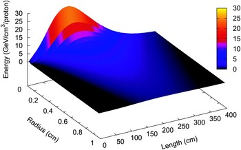
In this section, we present results of energy loss of 7 TeV/c LHC protons in a solid graphite target, which have been calculated using the FLUKA code (Fasso et al., Reference Fasso, Ferrari, Roesler, Sala, Battistoni, Cerutti, Gadioli, Garzelli, Ballarini, Ottolenghi, Empl and Ranft2003, Reference Fasso, Ferrari, Ranft and Sala2005), which is a fully integrated particle physics and multi–purpose Monte Carlo simulation package capable of simulating all components of the particle cascades in matter up to multi-TeV energies. For this study, the geometry for the FLUKA calculations was a cylinder of solid graphite with radius = 1 m and length = 5 m. The energy deposition is obtained using a realistic two–dimensional beam distribution, namely, a Gaussian beam (horizontal and vertical σrms = 0.2 mm) that is incident perpendicular to the front face of the cylinder. In Figure 1, we present the energy deposition in GeV per proton per unit volume in solid graphite as a function of the depth into the target and the radial coordinate. It is seen that the maximum value of the energy deposition in this case is on the order of 30 GeV/p/cm3 and the protons penetrates up to 3.5 m into the solid graphite.
(Color online) Energy deposition in a solid graphite cylinder by a single 7 TeV proton per unit volume, calculated by the FLUKA code.

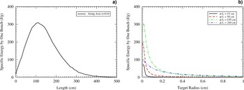
In Figure 2, we plot the specific energy deposition by a single LHC bunch (1.15 × 10¹¹ protons) in the target. Figure 2a shows the specific energy deposition along the axis (r = 0.0) and it is seen that a maximum specific energy deposition of about 0.3 kJ/g is achieved. The peak of the distribution lies at longitudinal position of 110 cm and the peak is very wide. In case of a copper target, on the other hand, the maximum specific energy deposition is about 2.2 kJ/g while the peak is much sharper and lies at a longitudinal position of 16 cm (Tahir et al., Reference Tahir, Kain, Schmidt, Shutov, Lomonosov, Gryaznov, Piriz, Temporal, Hoffmann and Fortov2005d, Reference Tahir, Goddard, Kain, Schmidt, Shutov, Lomonosov, Piriz, Temporal, Hoffmann and Fortov2005e, Reference Tahir, Schmidt, Shutov, Lomonosov, Piriz, Hoffmann, Deutsch and Fortov2009b). This difference of the behavior in the two cases is due to the large density difference between the two materials.
(Color online) Specific energy deposition by one LHC bunch in solid graphite: (a) along axis (r = 0.0); (b) along radius at four different points on the axis.

Figure 2b shows the specific energy deposition by a single bunch along the radial direction at four different positions on the axis. A comparison with the case of a copper target (Tahir et al., Reference Tahir, Kain, Schmidt, Shutov, Lomonosov, Gryaznov, Piriz, Temporal, Hoffmann and Fortov2005d, Reference Tahir, Goddard, Kain, Schmidt, Shutov, Lomonosov, Piriz, Temporal, Hoffmann and Fortov2005e, Reference Tahir, Schmidt, Shutov, Lomonosov, Piriz, Hoffmann, Deutsch and Fortov2009b) shows that the distribution is more spread in the radial direction in case of graphite. This again is due to the fact that the shower spreads out in the graphite target differently due to its lower density.
5. HYDRODYNAMIC SIMULATION RESULTS
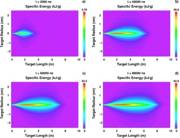
In this section, we discuss numerical simulation results of the thermodynamic and hydrodynamic response of a solid graphite cylindrical target that is facially irradiated by one LHC beam. The target length is assumed to be 10 m while the radius is 2.5 cm, and the density is considered to be 2.28 g/cm3. These simulations have been carried out using a two–dimensional computer code, BIG2 (Fortov et al., Reference Fortov, Goel, Munz, Ni, Shutov and Vorbiev1996), that is based on a Gudonov type numerical scheme. Equation of state data from Kerley (Reference Kerley2001) is used to model different physical states of graphite in the calculations. The 7 TeV/c proton energy loss data in solid graphite (in units of GeV/proton/cm3) calculated by the FLUKA code (Fasso et al., Reference Fasso, Ferrari, Roesler, Sala, Battistoni, Cerutti, Gadioli, Garzelli, Ballarini, Ottolenghi, Empl and Ranft2003, Reference Fasso, Ferrari, Ranft and Sala2005) that is presented in Section 3, is converted to units of kJ/g and is used as energy input to the BIG2 code. The resulting specific energy deposition achieved in the target at different times during beam irradiation is shown in Figure 3 on a length–radius plane. It is seen in Figure 3a that at t = 2000 ns, when only about 80 out of 2808 bunches have been delivered, a maximum specific energy of 5.7 kJ/g is deposited in the target. Figure 3b shows that at t = 40000 ns, when about 1570 bunches have been delivered, the maximum specific energy deposition is about 30 kJ/g. This value increases to about 35 kJ/g at t = 60000 ns and to 42 kJ/g at t = 89000 ns, which is the end of the pulse. This specific energy deposition level is comparable to what one may achieve at a dedicated facility, like FAIR (Henning, Reference Henning2004). Another interesting feature shown in these figures is that the energy deposition surface continuously moves toward the right in the longitudinal direction. The reason for this behavior is explained below.
(Color online) Specific energy deposition by one LHC beam in a graphite cylinder, length = 10 m, radius = 2.5 cm; each bunch consists of 1.15 × 10¹¹ 7 TeV/c protons, bunch length = 0.5 ns, two neighboring bunches are separated by 25 ns, transverse intensity distribution is Gaussian with σ = 0.2 mm; (a) at t = 2000 ns (about 80 out of 2808 bunches delivered); (b) at t = 40000 ns (about 1570 out of 2808 bunches delivered); (c) at t = 60000 ns (about 2350 out of 2808 bunches delivered), and (d) at t = 89000 ns (end of the beam).

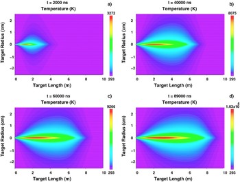
The target temperature distribution corresponding to Figure 3 is presented in Figure 4. It is seen in Figure 4a that at t = 2000 ns, a maximum temperature of about 3 × 10³ K is generated at the point of maximum energy deposition. The following figures show a steady increase in the temperature and it is seen that at the end of the pulse, a maximum temperature on the order of 10000 K is achieved in the target. This is the interesting regime of warm dense matter (WDM). Currently the scientific community shows great interest in warm dense matter phenomena, which are studied with intense laser and particle beams. Most of this work does address basic physics issues of matter under extreme conditions (Lopez Cela et al., Reference Lopez Cela, Piriz, Serna Moreno and Tahir2006; Ni, et al., Reference Ni, Kulish, Mintsev, Nikolaev, Ternovoi, Hoffmann, Udrea, Hug, Tahir and Varentsov2008; Piriz et al., Reference Piriz, Portuguez, Tahir and Hoffmann2002, Reference Piriz, Tahir, Hoffmann and Temporal2003a, Reference Piriz, Temporal, Lopez Cela, Tahir and Hoffmann2003b, Reference Piriz, Lopez Cela, Tahir and Hoffmann2005, Reference Piriz, Lopez Cela, Serna Moreno, Tahir and Hoffmann2006, Reference Piriz, Lopez Cela, Tahir and Hoffmann2008; Tahir et al., Reference Tahir, Hoffmann, Spiller, Maruhn and Bock1999, Reference Tahir, Hoffmann, Kozyreva, Shutov, Maruhn, Neuner, Tauscwitz, Spiller and Bock2000a, Reference Tahir, Hoffmann, Kozyreva, Shutov, Maruhn, Neuner, Tauschwitz, Spiller and Bock2000b, Reference Tahir, Kozyreva, Spiller, Hoffmann and Shutov2001a, Reference Tahir, Hoffmann, Kozyreva, Tauschwitz, Shutov, Maruhn, Spiller, Neuner, Jacoby, Roth, Bock, Juranek and Redmer2001b, Reference Tahir, Juranek, Shutov, Redmer, Piriz, Temporal, Varentsov, Udrea, Hoffmann, Deutsch, Lomonosov and Fortov2003, Reference Tahir, Juranek, Shutov, Redmer, Piriz, Temporal, Varentsov, Udrea, Hoffmann, Deutsch, Lomonosov and Fortov2004, Reference Tahir, Adonin, Deutsch, Fortov, Grandjouan, Geil, Gryaznov, Hoffmann, Kulish, Lomonosov, Mintsev, Ni, Nikolaev, Piriz, Shilkin, Spiller, Shutov, Temporal, Ternovoi, Udrea and Varentsov2005b, Reference Tahir, Deutsch, Fortov, Gryznov, Hoffmann, Kulish, Lomonosov, Mintsev, Ni, Nikolaev, Piriz, Shilkin, Spiller, Shutov, Temporal, Ternovoi, Udrea and Varentsov2005c, Reference Tahir, Spiller, Udrea, Cortazar, Deutsch, Fortov, Gryaznov, Hoffmann, Lomonosov, Ni, Piriz, Shutov, Temporal and Vrentsov2006, Reference Tahir, Schmidt, Brugger, Lomonosov, Shutov, Piriz, Udrea, Hoffmann and Deutsch2007a, Reference Tahir, Spiller, Shutov, Lomonosov, Gryaznov, Piriz, Wouchuk, Deutsch, Fortov, Hoffmann and Schmidt2007b, Reference Tahir, Kim, Matveichev, Ostrik, Shutov, Lomonosov, Piriz, Lopez Cela and Hoffmann2008b, Reference Tahir, Matveichev, Kim, Ostrik, Shutov, Lomonosov, Sultonov, Piriz, Lopez Cela and Hoffmann2009a, Reference Tahir, Schmidt, Shutov, Lomonosov, Piriz, Hoffmann, Deutsch and Fortov2009b; Temporal et al., Reference Temporal, Piriz, Grandjouan, Tahir and Hoffmann2003, Reference Temporal, Lopez Cela, Piriz, Grandjouan, Tahir and Hoffmann2005) or is related to inertial fusion physics (Bangerter et al., Reference Bangerter, MARK and Thiessen1982; Deutsch, Reference Deutsch1986; Logan et al., Reference Logan, Perkins and Barnard2008; Long & Tahir, Reference Long and Tahir1982, Reference Long and Tahir1986, Reference Long and Tahir1987; Piriz & Wouchuk, Reference Piriz and Wouchuk1992; Tahir & Long, Reference Tahir and Long1982, Reference Tahir and Long1983, Reference Tahir and Long1984).
(Color online) Target temperature corresponding to Figure 3.

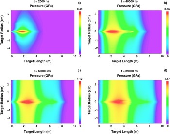
The high temperature generated by the beam in the target give rise to very high pressure, which is shown in Figure 5. It is seen in Figure 5a that at t = 2000 ns, pressure of 0.43 GPa is produced in the beam heated region that increases to 0.86 GPa at t = 40000 ns (see Figure 4b). The high pressure generates an outgoing radial shock wave that moves material away from the beam heated region, thereby leading to a continuous reduction in the density. As a consequence, the protons that are delivered in the subsequent bunches penetrate deeper and deeper into the target. This so called “tunneling effect” has also been observed in case of heavy ion matter interaction studies (Tahir et al., Reference Tahir, Kozyreva, Spiller, Hoffmann and Shutov2001a).
(Color online) Target pressure corresponding to Figure 3.

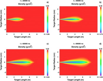
The above effect is clearly seen in Figure 6 where we plot the density distribution in the target at different times. It is seen in Figure 6a that at t = 2000 ns, the density along the axis in the beam heated region has decreased to 0.9 g/cm3. Figure 6b shows that at t = 40000 ns, the minimum density has become 0.7 g/cm3, while the low density region extends to about 6 m in the longitudinal direction. Further reduction in density and further extension of the low density region is shown by Figures 6c and 6d, respectively.
(Color online) Target density corresponding to Figure 3.

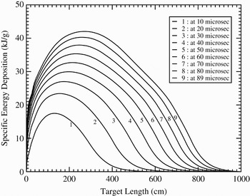
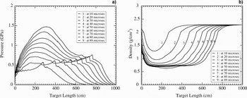
For a more quantitative discussion of the results, in Figures 7–9, we plot target parameters along the axis (r = 0.0) at different times. Figure 7 shows the specific energy deposition along the axis at intervals of 10 µs. It is seen that the specific energy deposition increases with time and one achieves an average specific energy deposition of about 40 kJ/g in a large part of the target at the end of the pulse. It is also seen that the peak of the distribution and the point where the specific energy deposition goes to zero, continuously move toward the right in the longitudinal direction. This is a direct consequence of the “tunneling effect.”
Specific energy deposition profiles along the axis (at r = 0.0) at different times during irradiation.

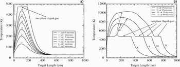
(a) Temperature profiles up to 5 µs and (b) Temperature profiles after 5 µs, along the axis (at r = 0.0) at different times during irradiation.

(a) Pressure profiles; (b) Density profiles, along the axis (at r = 0.0) at different times during irradiation.

The corresponding temperature profiles are shown in Figures 8a and 8b. It is seen from Figure 8a that the temperature increases to above 4000 K at t = 3 µs, but at t = 5 µs, the top of the curve becomes flat. This is because the target material enters into a two–phase liquid–gas region, which limits the temperature increase. This is further seen in Figure 8b where we plot the temperature profiles along the axis at later times. It is seen that at t = 15 µs the two–phase region extends up to about 4 m in the longitudinal direction and a small hump appears just before L = 2 m, which represents the fully gaseous state. Curves plotted at later times show that the position of the two–phase liquid–gas region continuously shifts toward the right while to the left of this region, more and more material becomes gaseous and the temperature in this region continues to increase as more and more energy is deposited by the beam. At the end of the pulse, we achieve a maximum temperature of about 10000 K in the target and the protons penetrate the entire length of the target.
In Figure 9a, are plotted the pressure profiles along the axial direction at different times during the irradiation. It is seen that there are two peaks in each curve. One is the main peak that corresponds to the maxima of the energy deposition curve, while the second is a smaller peak near the end of the curve, which represents the end of the deposition region. It is seen that the positions of these curves shift toward the right, which is again due to the deeper penetration of the protons as discussed before.
Figure 9b shows the corresponding density profiles that show substantial density decrease and propagation of the density depletion front toward the right during the beam irradiation. These simulations show that using this dynamic model, the 7 TeV/c LHC protons will penetrate about 10 m into solid graphite, where the range of these protons in the solid target is about 3.5 m.
We note that the proton energy loss data calculated by the FLUKA code that we use in our simulations assumes a solid target density whereas the density decreases substantially in the beam–heated region during the target irradiation. In fact, in practice, as the material density decreases, the rate of production of the secondary particles by the protons that are delivered in the following bunches, and hence their energy loss in that region significantly decreases that allows them to penetrate much longer distances than that predicted by a static model. It is difficult to figure out a precise density dependence in this case, nevertheless we account for this effect by normalizing the specific energy deposition with the line density in each simulation cell of the computer code at each time step. This allows one to study this problem under dynamic conditions. These simulations have provided us with very good insight into this important problem. However, we note that a full quantitative understanding of this difficult problem is only possible by carrying out fully integrated simulations with the FLUKA code coupled to the BIG2 code. This work is in progress, but will take more time.
6. CONCLUSIONS AND OUTLOOK FOR THE FUTURE
Consequences of the full impact of an LHC beam with a solid graphite target have been analyzed with the help of numerical simulations that have been carried out using a two–dimensional hydrodynamic computer code, BIG2. The energy loss of 7 TeV/c LHC protons in the target is calculated employing the FLUKA code and this data is used as input to the BIG2 code. It has been found that the density in the beam heated region substantially decreases due to the outgoing radial shock wave generated by the high pressure induced due to energy deposition by only about 80 out of 2808 proton bunches. As a consequence, the protons that are delivered in the following bunches penetrate deeper into the target that leads to a significant lengthening of their range in the target. A static model predicts a penetration depth of about 3.5 m in solid graphite whereas our simulations show that by the end of the pulse (89 µs), these protons will penetrate up to 10 m. This effect must be taken into account while designing a protective system against such an accident, for example, a sacrificial beam stopper. It is also worth mentioning that a temperature of about 10000 K is achieved in the beam heated region and the target is transformed into a gaseous state. The entire length of the target (10 m) is seriously damaged by such an impact.
As mentioned in the previous section, we use the proton energy loss data calculated assuming a solid density whereas the density decreases substantially during the course of heating. This should result in a corresponding reduction in the rate of generation of the secondary particles that would lead to a decrease in energy deposition. We take into account this effect by normalizing the energy loss data (calculated at solid density) with respect to the line density along the axis in the hydrodynamic calculations in each simulation cell at each time step. This is a reasonable approximation and use of this model has helped us to understand this problem. However, for a full quantitative analysis, it is necessary to couple the FLUKA and the BIG2 codes and carryout integrated simulations. This work is in progress.
ACKNOWLEDGMENTS
The authors would like to thank G.I. Kerley for providing the equation-of-state data for carbon. This work was financed by the BMBF.