

Introduction
The exact biomechanical valve mechanism of the Eustachian tube remains unsolved. The Eustachian tube is constructed as a complex aeration valve for the middle ear, connecting the middle ear to the pharynx. The extent of dysfunction is relevant in understanding the pathogenesis of secondary otological diseases, such as different forms of acute or chronic otitis media. The underlying mechanism of Eustachian tube dysfunction remains poorly understood, except for obvious causes like nasopharyngeal tumours or cleft palate.
Today, available imaging diagnostics suitable for the Eustachian tube are flexible or rigid endoscopy, or radiological multiplanar imaging. Computed tomography offers good skeletal imaging, and by identifying the pharyngeal entrance, overall length and angles can be assumed, but there can be no detailed information gained regarding the cartilaginous part.Reference Takasaki, Takahashi, Miyamoto, Yoshida, Yamamoto-Fukuda and Enatsu1 Magnetic resonance imaging offers a limited resolution for small anatomical parts like the Eustachian tube, and is associated with a long scanning time to obtain adequate resolution.
Given that there are many anatomical areas within the field of otorhinolaryngology that are difficult to visualise, the specialty has always benefited from evolving techniques of imaging. Interventions in the frontal or lateral skull base, or in the larynx, for instance, have become less invasive, safer and more efficient with these advances in medical imaging and additional functions, such as using multiphoton microscopyReference Yeh, Kao, Jung, Chen, Nelson and Tromberg2 or narrow-band imaging.Reference Aloisi, Sonoda, Gardner, Park, Elliott and Zhou3 Improved diagnostics in Eustachian tube dysfunction can be assumed with this evolution of imaging techniques.
Endoscopic imaging of the Eustachian tube has been described before.Reference Di Martino, Walther, Maneschi and Westhofen4–Reference Poe, Abou-Halawa and Abdel-Razek6 The torus tubarius can be visualised with established endoscopes, with the main emphasis on the morphology and functional opening movement (e.g. swallowing, yawning, or Valsalva or Toynbee manoeuvres). The neural-triggered function of the Eustachian tubeReference Songu, Aslan, Unlu and Celik7 leads to decreased opening resistance, mainly by the controlled movement of the attached velar muscles in the manner of a hydraulic valve. Intraluminal ultrasound of the Eustachian tube has not been reported, because of the oversized diameters of the ultrasound heads compared to the lumen of the Eustachian tube.
Often the pathogenesis of Eustachian tube dysfunction cannot be diagnosed with available imaging techniques. The functional diagnostics available today offer only indirect measures of Eustachian tube dysfunction, and fail to give insight into the pathological mechanism of the dysfunction. Several pathological mechanisms are discussed. An increased opening resistance of the Eustachian tube may be caused by: intraluminal debris, damaged epithelial integrity, adhesions restricting the physiological extent of the opening movement of the Eustachian tube, or subepithelial pathological findings such as hypertrophy of lymphoid tissue or oedema.Reference Di Martino8
In the resting position, the lumen is closed and therefore not accessible for endoscopic inspection. Investigation of the Eustachian tube, either non-invasively through the nose or mouth via the pharyngeal opening of the Eustachian tube, or through transtympanic access during middle-ear surgery, is limited by the direct contact of the optical lens with the endoluminal epithelium of the Eustachian tube or mucus therein. Effective image quality can only be achieved if there is no obstruction between the distal end of a conventional endoscope and the epithelial surface. Furthermore, given the size and cylindrical design of the endoscope (with a blunt distal end), there is significant mechanical resistance of the mucosal walls whilst attempting to slide through the Eustachian tube, with the potential risk of epithelial damage.
A similar problem exists, for example, during oesophagoscopy, where the problem of direct lens contact and mechanical resistance might occur during forwarding movement of the scope. In order to maintain an open oesophageal lumen, the first solution was a specially designed straight tube for rigid oesophagoscopy, still widely used today. The second solution was the use of a flexible endoscope, introduced into routine medical practice in the second half of the twentieth century. Both methods maintain the patency of the lumen: the first by the specially shaped form of the rigid endoscope, the second with constant airflow over the outlet in the tip. This prevents laceration of the epithelial surface and facilitates excellent image quality. Until now, there is no adequate endoluminal endoscope available to resolve these challenges in the Eustachian tube. Better diagnostics of the luminal surface and the superficial layers of the Eustachian tube are a prerequisite for an improved understanding of the pathogenesis of Eustachian tube dysfunction.
Luminal optical coherence tomography is a light-based imaging modality widely used in the clinical diagnosis of cardiac disorders.Reference Vignali, Solinas and Emanuele9 The underlying mechanism of this intravascular technique can be compared to ultrasonographic B-scan imaging, with the difference being that light in the near-infrared range is used rather than ultrasound.Reference Kranjec, Mrevlje, Legutko and Dudek10 In optical coherence tomography, the catheter is positioned in the lumen of a coronary artery, where the functional part of the catheter, the sensor, is placed in the area of interest. Then, the optical lens element, which is located inside the translucent outer tube, records the area of interest by retrieval of a cross-sectional image. In this way, layers of consecutive cross-sections of the lumen are reformatted in three dimensions.
Luminal optical coherence tomography has proven to be a useful tool, both in difficult conditions of patients with stable coronary artery disease and in acute coronary syndrome. It can provide detailed insight into the coronary artery wall, showing: subendothelial ruptures and plaques, luminal stenosis, thrombogenesis, conditions of stented areas including stent apposition or malapposition, vascular dissection, tissue prolapse through a stent, and other findings.Reference Kranjec, Mrevlje, Legutko and Dudek10, Reference Roleder, Jakala, Kaluza, Partyka, Proniewska and Pociask11 As the cross-sectional images are in high resolution, optical coherence tomography has been considered to be an optical biopsy method.Reference Roleder, Jakala, Kaluza, Partyka, Proniewska and Pociask11 It is now accepted as routine practice in percutaneous coronary interventions, especially in stenting. In other medical fields, optical coherence tomography with different settings has been shown to be useful as an additional diagnostic tool; for example, in ophthalmology,Reference Kardon12 pulmonology or thoracic surgery of the respiratory tract,Reference Hanna, Saltzman, Mukai, Chen, Sasse and Milliken13 and otolaryngology. For the latter, there are some reports of optical coherence tomography used in laryngology,Reference Volgger, Arens, Kraft, Englhard and Betz14–Reference Kobler, Chang, Zeitels and Yun16 and for examining the tympanic membrane and middle ear.Reference Cho, Lee, Jung, Jang and Kim17 Nevertheless, optical coherence tomography is not widely used as a routine clinical diagnostics tool and, to our knowledge, the non-invasive luminal optical coherence tomography has not yet been applied in the examination of the Eustachian tube.
In order to be a successful diagnostic tool for the Eustachian tube, the optical coherence tomography catheter should be small enough to pass through the narrowest portion of the Eustachian tube, the isthmus. Furthermore, as it is generating cross-sectional images of the lumen, the luminal surface must be in contact with the superficial epithelium or filled with liquid to facilitate contact with the superficial adjacent tissues along the entire axis, so as to enable three-dimensional (3D) reconfiguration. Optical coherence tomography creates an almost microscopical resolution of 10–20 μm, meaning its resolution is 10 times higher than intraluminal ultrasound.Reference Roleder, Jakala, Kaluza, Partyka, Proniewska and Pociask11, Reference Mrevlje, Legutko, Jakala, Noc, Dudek and Birkemeyer18 Optical coherence tomography uses the digital imaging and communications in medicine (‘DICOM’) standard for the 3D dataset. With this applied standard, it is possible to format a 3D image for further quantitative measurements of length and – regarding the limited penetration depth – volume measurement. Access via a transnasal catheter is established by balloon dilatation of the Eustachian tube, which is a technique in general clinical use.Reference Schroder, Lehmann, Ebmeyer, Upile and Sudhoff19 The challenge of positioning the catheter in the Eustachian tube is resolved by the use of a semi-rigid application tool with an angled tip, which can then be placed in the torus tubarius.
The current study aimed, therefore, to investigate the feasibility of intraluminal optical coherence tomography in the Eustachian tube via a transnasal approach, and to get the first insight into its respective diagnostic potential.
Materials and methods
This study was performed using two fresh frozen heads of blackface sheep, as received from a slaughterhouse (Hencke Fleischwaren, Bad Bevensen, Germany). Before the experiments, computed tomography (CT) scans were performed using an orbital protocol (LightSpeed16; General Electric, Fairfield, Connecticut, USA). For handling reasons, the cadaver heads were dissected whilst still frozen, resecting in a coronal section the anterior part of the nose up to the choanae and the skull base posterior to the tympanic cavity. This provided perfect visualisation of the cartilaginous portion and the tympanic region at all times. After thawing the heads at room temperature, the catheters were inserted into the Eustachian tubes of both sheep sequentially, through the pharyngeal opening of each Eustachian tube.
For the experiments with a stent inside the Eustachian tube, a ProKinetik Energy stent (Biotronik, Berlin, Germany) was used, consisting of a non-degradable cobalt-chrome alloy with a strut thickness of 60 μm and a recoil of less than 5 per cent. The stent was mounted on an expandable balloon catheter (rapid exchange catheter, length of 1.4 m), inflated at 10 bar for 2 minutes and expanded to its nominal size of 2 × 20 mm.
Scans were performed using an optical coherence tomography scanner (Ilumien Optis; St Jude Medical, St Paul, Minnesota, USA) equipped with a Dragonfly Duo catheter (St Jude Medical). The catheter has a diameter of 2.7 F (0.9 mm), and a minimal distance of 19 mm from the tip of the catheter to the scanner. The catheter was inserted through the Eustachian tube into the opened middle ear, and measurements were performed whilst moving the scanner unit back through the Eustachian tube towards the pharynx. The maximum distance for movements of the scanner was 54 mm.
The scanning protocol used was calibrated for coronary arteries, generating the following automatic measurements: the minimal, maximal and mean diameter of the lumen (mm), and the luminal area (mmReference Yeh, Kao, Jung, Chen, Nelson and Tromberg2). In one scanning procedure, 540 serial cross-sectional images were generated, meaning that a cross-sectional image was generated every 0.1 mm, with a line scan rate of 5 mm/second.Reference Mrevlje, Legutko, Jakala, Noc, Dudek and Birkemeyer18 The generated images were continuous perpendicular cross-sections of the Eustachian tube over the entire distance from the middle ear to the pharynx, providing an infiltration depth of roughly 2 mm from the mucosal surface. A calculated localisation image was placed below each cross-section showing the position of the cross-section in the tube with additional information of the reconstructed plane.
The image resolution was 1048 × 1048 pixels, corresponding to 10 μm per pixel, with an optical depth penetration up to 2 mm. For image acquisition, a wavelength of 1300 nm was used, reflected peripherally by a microprism at a perpendicular angle through the external translucent catheter. The brightness was set on a window level of 127 HU, with contrast on a window width of 255 HU.
In a first attempt, the catheter was inserted through the Eustachian tube without any dilatation. In a second attempt, the Eustachian tube was expanded by intraluminal continuous flushing with isotonic saline solution through an intravascular catheter over the protympanum to the Eustachian tube (Vasofix Braunüle 14 G, 2.2 mm × 50 mm; Braun Melsungen, Melsungen, Germany). This was performed using a 10 ml syringe (Injekt Solo; Braun Melsungen), with a maximum resultant water pressure of 1 bar. In a third attempt, the Eustachian tube was stented, as described above, over the transpharyngeal access.
The cross-sectional images of the optical coherence tomography were compared with histological cross-sections, generated in a previous studyReference Pohl, Schuon, Miller, Kampmann, Bultmann and Hartmann20 with the following protocol. The specimens were washed in physiological saline solution and fixed in formalin (3.5 per cent, pH 7.4) for two weeks. Prior to embedding in methyl methacrylate (Merck, Darmstadt, Germany), dehydration of the specimen via an increasing ethanol series (70, 80, 90 and 100 per cent) was carried out. Each step was performed overnight, and finalised with methyl methacrylate infiltration and polymerisation in a water bath with increasing temperature (35°C to 40°C) for 2–4 days, depending on the status of polymerisation. Excess methyl methacrylate was removed with a plaster model trimmer (HSS 88; Wassermann Dental-Maschinen, Hamburg, Germany) until only the specimen remained. The specimens were cut into two halves, and fixed on a specimen holder to cut slices of approximately 33 μm thickness using a saw microtome (Leica SP1600; Leica Biosystems, Wetzlar, Germany), beginning in the middle of each Eustachian tube and following a perpendicular course to the pharynx. Staining of the slices was performed with alizarin red (Alizarin red S staining solution; Merck) and methylene blue (Löffler's methylene blue solution; Merck). First, the slices were covered for 45 seconds with methylene blue on a heating plate (80°C). After rinsing under distilled water, the slices were covered with alizarin red for 1.5 minutes. Following an additional rinsing step, the slices were dried in an incubator at 37°C overnight. The slices were digitised with a fluorescence microscope (Keyence® Biorevo BZ-9000®; 2× magnification, resolution of 3094 × 4094 pixels).
Results
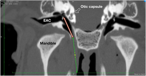
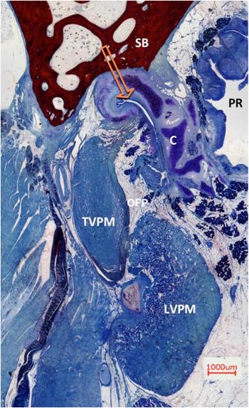
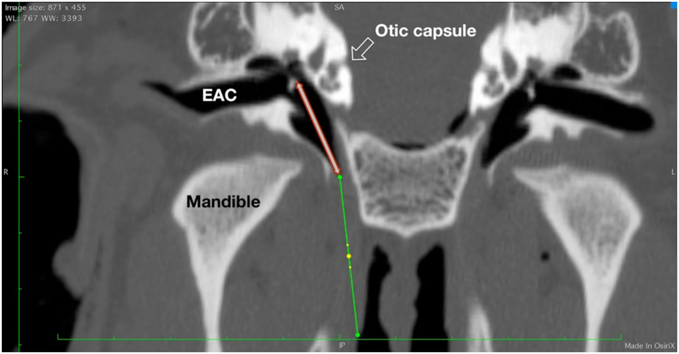
The optical coherence tomography catheter could be inserted from the nasopharynx through the Eustachian tube and up into the middle ear. The catheter proved to be flexible enough to adapt to the slightly curved course of the Eustachian tube. Iatrogenic stretching or artificial opening of the cartilaginous part of the Eustachian tube was minimal. There was no damage to the Eustachian tube (e.g. epithelial laceration or creation of a false passage by penetrating the Eustachian tube wall). No case of unwanted bending in any of the three test conditions was observed. The length of the tip (19 mm) entered the tympanic cavity, coming into contact with the delicate structures of the middle ear and the windows of the inner ear (Figure 1). A wide field histological cross-section of the structural elements and the adjacent surrounding tissue of the Eustachian tube are demonstrated (Figure 2).
Paraxial (coronal) computed tomography image, showing the axis of the Eustachian tube (green line) and the non-functional start-up length of the optical coherence tomography tip (19 mm, red-lined arrow). The latter extends from the bony part or isthmus region of the Eustachian tube to the posterior wall of the tympanon, passing the cochlea laterally, with its path crossing the delicate region of the ossicles and the oval and round window region of the middle ear. WW = window width; WL = window length; SA = superior anterior; EAC = external ear canal; R = right; L = left; IP = inferior posterior.
Overview of the Eustachian tube and the surrounding tissue. A histological cross-section of a right auditory tube in the midportion (view from front). The cartilage (C) is hugging the lumen, lined with respiratory epithelium. The pharyngeal recess (PR) with lymphoid adenoid tissue is located medial to the cartilage, the skull base (SB) is superior, the tensor veli palatine muscle (TVPM) is lateral and the levator veli palatine muscle (LVPM) is latero-inferior, beside Ostmann's fat pad (OFP). Rüdinger's safety canal is marked with the orange arrow. (Alizarin red S and methylene blue (Löffler's methylene blue) staining solutions; ×2)

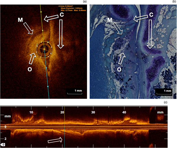
The first recording was conducted with the collapsed Eustachian tube in the closed (normal, relaxed) status (Figure 3a, b). The circular optical coherence tomography catheter provided a realistic and accurate image. The slit-formed shape of the Eustachian tube in these cross-sections made only the immediately adjacent part around the catheter visible, but not the distant corners of the Eustachian tube in the coronal plane. Figure 3b demonstrates in parallel the structural elements in a histological cross-section. The lumen of the Eustachian tube in the optical coherence tomography scan appeared more spindle-shaped than split-shaped (as seen in the histological section), a result of slight clamping due to the optical coherence tomography catheter. The opposing margins, in the vertical position, in the upper part of the Eustachian tube with the Rüdinger's safety canal and the inferior part neighbouring the Ostmann's fat pad, were poorly visualised in cross-sections. The superficial epithelium with its underlying soft tissue could be identified best in the orthogonal direction. Compared to histological slices of these cross-sections, it was possible to identify superficial structures, such as the respiratory epithelium, submucosa, cartilage and adnexal structures (mucous glands or lymphoid follicles), and bone (Figure 3a, b). Figure 3a includes the automated measurements as described above. The longitudinal course of the Eustachian tube is shown in Figure 3c, with the marked actual position of the cross-section.
Comparison of optical coherence tomography and histological cross-sections of the Eustachian tube (midportion). (a) Cross-section perpendicular to the axis of the optical coherence tomography fibre and the Eustachian tube, showing: a dark display of cartilage (‘C’ arrows, with a long medial and short lateral cartilaginous arm), tensor veli palatini muscle (arrow ‘M’), and subepithelial tissue with gland tissue (arrow ‘O’). Note the minimal spreading of the Eustachian tube with the optical coherence tomography fibre. The epithelium is in contact with the surface of the optical coherence tomography fibre; therefore, the automatic measurement of the lumen is more or less equal to the fibre dimension (area = 0.54 mm2) and diameter (mean = 0.83 mm, minimum = 0.77 mm and maximum = 0.9 mm). (b) Detailed histological cross-section, showing the opening artifact in Rüdinger's safety canal, after fixation of the specimen with formalin (abbreviations same as in part a) (methylene blue (Löffler's methylene blue) staining solution; ×2). (c) Reconstructed sagittal axis from the pharynx (left) to the middle ear (right). The irregular appearance of the epithelial surface is caused by the plane nearby in the axis of the split-like lumen of the Eustachian tube. Note: In parts (a) and (c), the orientation of the respective other plane is marked with coloured lines (yellow and turquoise). In part (c), the position of the cross-section is marked again.

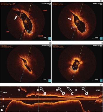
By inflating the Eustachian tube with physiological saline by continuous injection, the lumen opened up, showing a paisley-like pattern in the cross-sections (Figure 4a–e). The location of the optical coherence tomography catheter was in the inferior part of the slit-formed Eustachian tube, below the inverted J-form of the tubal cartilage. Figure 4 provides an overall adequate view of the epithelial surface and the underlying soft tissues. Functional elements, like a plica in Figure 4a, were demonstrated. Under the epithelium, which has an intense reflection, the cartilaginous entity is well defined. When the catheter was placed below the bulge of the short process of the lateral cartilage, the superior edge of the Eustachian tube with the Rüdinger's safety canal was eclipsed (Figure 4b, c). The isthmus was easily passable. In Figure 4c, the almost narrowest portion of the isthmus shows a continuous slit shape. The protympanum opens up inferiorly and laterally to the hypotympanum. Comparing the angulation of the long medial lamina of the cartilage from the pharyngeal site to the site near to the isthmus, there is a slight twisting from a more horizontal to a vertical orientation. This seems to suggest a gentle spiral form of the cartilage of roughly 18 degrees in this section of the Eustachian tube, where the cartilage is clearly visible.
Optical coherence tomography image of a dilated Eustachian tube. (a) In the dilated condition, a paisley-like pattern is apparent. The marking line (yellow and turquoise) is angled to the anatomical situation (cr. = cranial; caud. = caudal; med. = medial; and lat. = lateral). The outlined arrow correlates to a plica in the inferior-lateral region, nearby Ostmann's fat pad. The white arrow highlights the region of the short lateral arm of the cartilage (with a highly intense epithelial layer). The relevant area in the upper section of the Eustachian tube is neglected (orange circumference, white dots). (b) This shows the situation more distant from the pharyngeal opening. Note the origin of the tensor veli palatine muscle in the cartilage (white arrow). The outlined arrow demonstrates the embayment of Ostmann's fat pad region. (c) Closer to the middle ear, the diameter decreases significantly, remaining in a spindle shape. Note the angle of the long medial arm in comparison to part (a): an angulation of 18 degrees can be defined in this Eustachian tube. (d) This displays the bony protympanum, which opens inferior-laterally. (e) The reconstructed sagittal axis of the Eustachian tube (length approximately 2.7 mm), from the pharynx (left) to the middle ear (right), corresponding to the situation in part (a). The positions of the cross-sections in parts (a–d) are indicated at the x-axis by italic font letters and arrows. Note the hourglass-shape of the complete Eustachian tube and the forcipate narrowing of the pharyngeal opening.

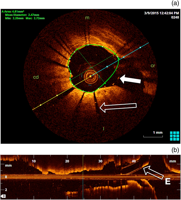
When placed inside the lumen of the expanded stent, the optical coherence tomography catheter shows the position of the stent in the lumen and the position in the cartilaginous part of the Eustachian tube (Figure 5). This is standard in the coronary artery with a circular shape, but is shown for the first time with optical coherence tomography in the Eustachian tube. The struts of the stent were visualised by a sharp signal in the position of the strut with a shadow behind it. The diameter of the stent on optical coherence tomography equates to the original stent in an expanded situation (2 mm).
Optical coherence tomography image of stented Eustachian tube. (a) The struts of the stent with direct epithelial contact are causing a shadowing effect. The struts in free lumen show a high signal by optical reflection (white arrow). (b) The reconstructed sagittal plane shows an ‘interrupted surface’ due to the shadow of the struts (outlined arrow), but overall the cartilaginous part of the auditory tube is unbolted by 2 mm. Note the inserted cannula for lumen expansion (from the right, arrow ‘E’). m = medial; cd = caudal; cr = cranial; l = lateral

Discussion
Imaging diagnostics currently available for the Eustachian tube often cannot reveal the cause for a dysfunction. Direct transluminal examination of the Eustachian tube focusing on morphology and function remains a challenge. A complete overview of the Eustachian tube displaying the surface and surrounding superficial soft tissue would enable further insight into Eustachian tube functionality and the aetiology of disorders. This information will most likely lead to more meaningful therapeutic options.
The well-developed luminal optical coherence tomography technology, used and evaluated in endovascular diagnosis of coronary artery disease,Reference Vignali, Solinas and Emanuele9 might be a promising option for future non-invasive inspection of the Eustachian tube. The transfer of catheter-based interventions from cardiology to otolaryngology has already been established in balloon dilatation of the Eustachian tube. A pernasal application tool is essential for positioning the balloon catheter in the torus tubarius. In the current study, luminal optical coherence tomography technology was tested in the collapsed, expanded and stented Eustachian tube. We analysed feasibility, handling and imaging, and additionally discuss possible alterations and modifications for future studies.
Passage of the relatively rigid optical coherence tomography catheter in these four Eustachian tubes, through the slightly curved track of the complete Eustachian tube from the pharynx up to the middle ear, was possible with a continuous low resistance and without resistance threshold. The diameter of the catheter is sufficiently small to easily pass the narrowest portion of the Eustachian tube, the isthmus. The atraumatic tip design ensures safe passage of the catheter through the entire Eustachian tube, without signs of false passage or even superficial epithelial damage. This could have been expected given the comparable specification of the optical coherence tomography catheter to the catheter used for balloon dilatation of the Eustachian tube. The pull-back of the scanning head inside the optical coherence tomography catheter is smooth, as expected based on the absence of severe bending or tilting. This indicates a general feasibility of a luminal optical coherence tomography in the Eustachian tube for diagnostic purposes.
The functional array for recording the images covers the complete length of the Eustachian tube, from the middle ear to the pharyngeal opening, in one approach, but a navigating technique is necessary to obtain feedback on the depth of insertion. In the coronary situation, an angiographic setting is used. For the Eustachian tube, a pharyngoscopic or otoscopic control might be a solution, with an application tool as used in balloon dilatation of the Eustachian tube. The application tool limits the insertion depth of the balloon catheter inside the Eustachian tube. For additional safety, a pre-investigation CT or cone-beam CT scan can provide more information, especially if there is altered anatomy, after trauma, tumour or a syndromal malformation such as cleft palate.
Furthermore, the application of continuous water pressure, as used in the current study, might cause damage (barotrauma) to the tympanic membrane and even, though much less likely, to the ossicles or windows of the inner ear. Additionally, a bacterial or viral infection of the middle ear might arise if the fluid is contaminated. A combination of optical coherence tomography with a local low-pressure balloon might offer a safer procedure, without the risk of collateral damage.
Optical coherence tomography allows visualisation of the complex functional luminal surface of the Eustachian tube. The images provide a detailed, high-resolution picture of the surface and the superficial soft tissue. The tissue penetration and, therefore, the delineation of the displayed depth, is dependent on the relative reflection of the catheter's emitted light. The respiratory epithelium is characterised by a definite high-intensity reflection, as already described by other authors.Reference Hanna, Saltzman, Mukai, Chen, Sasse and Milliken13 This epithelial layer equates to the intima layer of the coronary vessel.Reference Mrevlje, Legutko, Jakala, Noc, Dudek and Birkemeyer18
The appearance of the Eustachian tube in the closed position, with the catheter in situ, is slit-like with a spindle shape around the catheter in the cartilaginous part. The bony part shows the opening to the protympanum and the further opening to the hypotympanum. In the open situation, the cartilaginous part forms a paisley-like pattern, with the isthmus and bony part being unaffected.
The catheter in the images can be identified easily, as a result of the circular imaging technique from the centre. In relation to the Eustachian tube, the catheter is located in a more lateral and caudal position, opposite to the hook-shaped apical part of the Eustachian tube, where the long medial lamina of the cartilage turns towards the short lateral lamina. The catheter is relatively stiff, but allows a limited bending paraxially with a pernasal application tool in the Eustachian tube. In order to facilitate an image in the most cranial or caudal regions of the Eustachian tube, the catheter has to be positioned in the area of interest. Especially in undisplayed areas, the invaginated cranial course of the cartilaginous hook, formed by medial and lateral lamina of the cartilage (Rüdinger's safety canal), was not visually accessible over the whole distance in every cross-sectional image, as the necessary light energy was lost by reflection and absorption in the convex medial wall of the Eustachian tube (Figure 4a, b). A possible solution for this ‘blind spot’ is the described re-positioning of the catheter achieved by moving the application tool cranially in the direction of Rüdinger's safety canal.
Compared to the histological sections, the most distinct structure identifiable is the cartilage, showing a high transmission rate, as can be expected from translucent tissue with a low cell density. Optical coherence tomography generates cross-sectional images of the lumen and the superficial tissue layers of the Eustachian tube, which correlates with histological cross-sections.
The differentiation of the histological sections needs further research, as has been established in the coronary situation when classifying plaque, epithelial damage, stent position, endothelial ingrowth and inflammatory signs, for example.Reference Tearney, Regar, Akasaka, Adriaenssens, Barlis and Bezerra21, Reference Prati, Guagliumi, Mintz, Costa, Regar and Akasaka22 With further improvement of optical coherence tomography technology, increased diagnostic use can be anticipated.Reference Hanna, Saltzman, Mukai, Chen, Sasse and Milliken13 This can be achieved by better differentiation of changes due to inflammation, such as differentiation between granulocytes, lymphocytes and macrophages. In the near future, with polarisation-sensitive optical coherence tomography, or with the use of contrast microsphere agents,Reference Lee, Oldenburg, Sitafalwalla, Marks, Luo and Toublan23 an even better differentiation of inflammatory cells will be possible. As has been shown for coronary arteries with an occurrence of macrophages, a clear benefit for the non-invasive classification of inflammation in the Eustachian tube can be expected with this method.
Proper differentiation between subepithelial exocrine glandular tissue and lymphoid tissue is not yet possible with the obtained image quality. Furthermore, given the diameter of the cartilaginous Eustachian tube with its functional components of soft tissue (measured in centimetres) and the limited optical depth penetration of optical coherence tomography (up to 2 mm), a complete overview of Ostmann's fat pad or the attached muscular system of levator veli palatini and tensor veli palatini was not achieved. This finding correlates to the situation in a coronary artery, where the intima and media are displayed, but not the adventitia of the vessel.Reference Mrevlje, Legutko, Jakala, Noc, Dudek and Birkemeyer18
When applying optical coherence tomography after the insertion of a stent into the Eustachian tube, the total reflectiveness of the stent struts was displayed clearly, with high local signals and a radial shadowing behind (peripheral circular spoke-like extensions). The direct sign of the stent is a highlighted reflection from the struts, the indirect sign shows a shadow and the area peripheral to the struts remains dark (Figure 5), which is comparable to the situation in stented coronary arteries.Reference Kranjec, Mrevlje, Legutko and Dudek10, Reference Roleder, Jakala, Kaluza, Partyka, Proniewska and Pociask11
The condition with the stented Eustachian tube showed the following aspects. The stent was located in the area of minimal resistance, in the caudal, inferior-lateral part of the Eustachian tube near to Ostmann's fat pad. The stent used here (diameter of 2 mm) filled the lumen only partially; the circumference of the stent was much smaller than the circumference of the lining epithelium of the Eustachian tube. It can be assumed that the effect of balloon dilatation of the Eustachian tube is dependent on the diameter of the balloon (available from 3 to 8 mm for this purpose): only a diameter and circumference large enough is likely to have a therapeutic effect. The purpose of the stent in the Eustachian tube is eased aeration of the middle ear by a decreased opening resistance of the Eustachian tube. By having a stent chronically implanted in the Eustachian tube, at least some tissue reaction will occur.Reference Lee, Oldenburg, Sitafalwalla, Marks, Luo and Toublan23 As with optical coherence tomography in the coronary situation,Reference Vignali, Solinas and Emanuele9, Reference Kranjec, Mrevlje, Legutko and Dudek10 it is expected that tissue ingrowth of the stent, inflammatory tissue reactions or epithelial damage can also be investigated in the Eustachian tube using this technique.
The longitudinal shape of the Eustachian tube, shown in the axial reconstruction plane, is like an hourglass, with the narrowest diameter in the cartilaginous–osseous junction. The diameter increases towards the peripheral opening of the pharyngeal torus tubarius.
Although we are confident that damage within the Eustachian tube is unlikely, we see limitations and the potential for damage to middle-ear structures in the axial direction of the catheter because of the relatively long non-functional tip, which was initially engineered to make this procedure safe for use in the coronary artery. The tip of the available catheter (19 mm) is too long to be used in vivo: the ossicles are positioned in a straight line about 12–15 mm distant from the distal protympanum in humans. A much smaller tip length is indicated in order to reduce the risk of direct damage to these middle-ear structures.
Optical coherence tomography enables visualisation of the entire length of the Eustachian tube, both the osseous and cartilaginous parts. Obstructions such as a stenosis or collections of mucus and other debris might be detected.
The almost continuous sequence of cross-sectional images suggested a slightly spiralled conformation of the cartilage over the axis of the Eustachian tube from the middle ear to the pharynx, with a tendency to a medial shift of the inferior border of the medial lamina (18 degrees in the displayed section of the Eustachian tube in Figure 4). The spiralled forms of biomechanics are common in physiological anatomy, as in functions of the foot, the hip and many other regions such as the heart.Reference Nayak, Shajahan, Panfilov and Pandit24 This finding of spiralled conformation of the longitudinal axis for the Eustachian tube cartilage has, to our knowledge, not been described before.
This study showed a transfer of the already established diagnostic tool of luminal optical coherence tomography, used for coronary arteries, to the Eustachian tube. Currently, there are some limitations that prevent a human in vivo application. However, when the discussed issues, such as refinement of the tip with significant shortening, and the safe and practicable placement of the functional array of the optical coherence tomography catheter in the Eustachian tube, have been resolved, the applicability for future in vivo studies is highly promising. The simultaneous luminal application of optical highly viscous gel or fluid, or a low-pressure balloon, might deliver further insights into the biomechanics of passive elasticity.
With a shorter recording time, functional imaging is possible in awake subjects when swallowing, yawning, or performing Valsalva or Toynbee manoeuvres. This is expected to give further insight into Eustachian tube biomechanics, with a focus on the cartilage in 3D, and the involved tensor and levator veli palatine muscles, in direct proximity to the Eustachian tube lumen. The localisation of a reduced Ostmann's fat pad and consecutive altered luminal conformation with optical coherence tomography is likely to provide information about position and amount for augmentation techniques in patients suffering from a patulous Eustachian tube, even when a complete overview of the Ostmann's fat pat is not possible.
• An ex vivo study was conducted to test feasibility and possible diagnostic use of optical coherence tomography in the Eustachian tube
• Two sheep cadaver heads were examined bilaterally in three conditions: closed, actively opened and stented
• Placement of the optical coherence tomography catheter was made without difficulty
• Superficial tissue could be differentiated and stent position evaluated
• Optical coherence tomography in the Eustachian tube is potentially a feasible, rapid and non-invasive diagnostic method
• Technical modifications of the catheter are mandatory before application in patients
Conclusion
Optical coherence tomography with a luminal catheter-based sensor offers a new, non-invasive approach, which can deliver new insights both into the morphology and function of the Eustachian tube. This study showed a general feasibility of optical coherence tomography for imaging diagnostics of the Eustachian tube. Images show high-resolution, two-dimensional, coronal cross-sections, and the technique enables 3D reconstruction over the Eustachian tube axis. For in vivo application, the optical coherence tomography catheter has to be modified to reduce the risk for damage of middle-ear structures. Nevertheless, the technique itself appears to be a promising tool for investigating luminal morphology and superficial tissues of the Eustachian tube, and stented Eustachian tubes.
Acknowledgements
The authors would like to thank Mr Tony Markus for his valuable comments and language corrections of the manuscript. This study was supported by the Federal Ministry of Education and Research (‘BMBF’) project ‘Response – Partnership for Innovation in Implant Technology’ (grant code: FKZ 03ZZ0902E).
Competing interests
None declared