I. INTRODUCTION
The aim of TARGET (Top Amplifier Research Groups in a European Team) was to overcome the fragmentation of European research in the field of microwave power amplifiers (PAs) for broadband wireless access by creating a progressive and durable integration of research capacities of the network partners [Reference Magerl and Kommenda1]. After 4 years, European technology and research in the fields of active power devices, of the characterization and simulation of materials and devices, of amplifier design and linearization, and in the field of broadband transmitter system design have attained a leading role in the world.
TARGET brought together 49 top amplifier research groups consisting of 220 researchers and 70 doctoral students (coming from 15 EU member countries and one associated country) that have in the past 4 years published two books [Reference Garcia, Zamanillo and O'Droma2, Reference Schreurs, O'Droma, Goacher and Gadringer3] and more than 400 conference and journal papers based on results achieved within TARGET. This integration was pursued with the aim to
– Create a durable co-operative network.
– Establish a virtual center of excellence.
– Stimulate and coordinate world-class PA research.
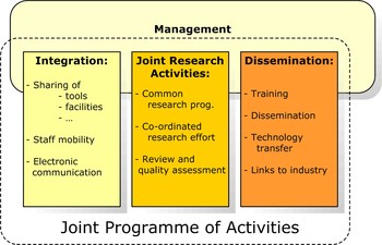
The three main strands of the joint program of activities (JPA) within the network
– Integration
– Joint research
– Dissemination
were kept together by both scientific and highly efficient network and financial management. This scheme is shown in Fig. 1.
TARGET’s joint program of activities.

A total of 40 work packages in the four fields of activities shown in Fig. 1 were active over the full 4 year funding period of the network. The total amount of funding was 8 million Euros.
II. TARGET OBJECTIVES AND WORK PACKAGES
The general project goals can be broken down to the following more tangible project objectives. With respect to creating a durable co-operative network these objectives are to
– Provide a common electronic platform for regular exchange of information.
– Establish an internal forum for regular discussion of scientific work.
– Create a program for the exchange of scientists and doctoral students.
The goal to create a virtual centre of excellence is translated into the following objectives:
– Create a pool of lab software for shared use.
– Establish common virtual lab infrastructures.
– Organize tutorials and special sessions at conferences.
– Establish summer schools.
– Provide internal PA design and prototyping services and establish rules for the use and exploitation of IPRs.
In order to stimulate and co-ordinate world-class research the following objectives are formulated:
– Initiate a common research program that establishes co-operative practice.
– Define and co-ordinate research efforts to gain third party funding.
– Create a joint research program that crosses traditional topical barriers.
– Establish close links to excellent research groups outside Europe.
– Install instruments for review and quality assessment.
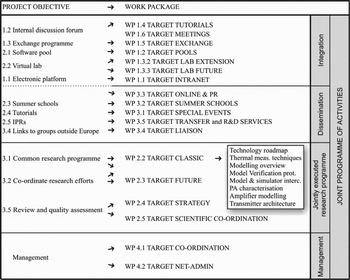
As shown in Fig. 2, each of these objectives corresponds to one work package (WP) or to one work package group. Furthermore, these work packages can be mapped on the three strands of activities of the JPA, namely “integration”, “dissemination”, and “jointly executed research programme”.
Mapping of project objectives onto work packages.

In the following, just a few examples of results achieved by the work packages belonging to the “integration” group are given. Within the “Tutorials” work package, a total of 30 meetings of TARGET sub-groups with special research interests were organized, and roughly one-third of these meetings were held on-line. Within the students’ exchange program, we had a total of 54 exchange visits of more than 1 month duration and four so-called strategic exchanges where small groups of students were invited, e.g. to highly specialized labs in order to get a dedicated technological education within 3–4 days. In the framework of the “Pools” work package, we collected up to now 17 software tools written and uploaded into our shared knowledge platform by TARGET members that were downloaded 168 times.
Similarly successful were our dissemination activities that made the TARGET research achievements accessible to the scientific community. We organized seven winter and summer schools for doctoral students, we offer a total of 16 educational and lab services to our customers, and we organized 29 short courses, workshops, and focused sessions at all major international microwave conferences.
III. TARGET COMMUNICATION
It is a truism that communication is a key factor in every cooperative project, both within the consortium and to the outside. But communication does not “just happen”, it requires defined structures, which has been rightly acknowledged from the onset, and therefore has been firmly rooted in TARGET’s work plan matrix.
A) Internal communication
A geographically scattered network requires one common platform, which is accessible to all its members. WP 1.1 Internet developed an intranet solution based on open software called Plone, a flexible and extendable system that offers various modules, including for instance event registrations and electronic voting. The intranet provides all relevant project documents, presentations, meeting minutes, etc. as well as shared software offered for download within the WP “Pools”. Furthermore, a shared knowledge center has been established that provides all the intellectual work developed within TARGET: internal reports and deliverables, tutorials, publications, presentations from summer schools, etc.
Further to this, an internal newsletter had been created as part of WP 3.3 “Online and PR”, which informed in 15 editions about all TARGET events (such as summer and winter schools, tutorials, workshops, the exchange program), introduced new work packages and summarized the results of finished ones, and generally informed about all relevant topics.
Electronic communication cannot substitute personal contact, and regular meetings were therefore an integral part of the work plan. Two work package meetings per year were a minimum for scientific work packages, the Steering Committee met every 2 months, and the member representatives gathered for the board meeting once every year (organized by WP 1.6 “Meetings”). These board meetings proved to be an important pillar in the TARGET building: not only was the consortium informed about the progress and the new plans and made decisions based on the rules laid down in the consortium agreement, but it was also a unique opportunity to engage in common, fruitful discussions (which is quite remarkable, considering that this is not self-evident with a big group in an auditorium).
B) External communication
The TARGET website (www.target-net.org) acts as the projects “business card” (provided by WP 1.1 “Internet”). It informs about the project, events, services offered by the network, gives relevant contact data, and includes a press corner. Thanks to the underlying content management system; it can be easily kept up-to-date with the latest news.
A central dissemination work package is WP 3.1 “Special Events”. Its main goal was to ensure proper participation of TARGET network partners to selected international conferences not only with their scientific contributions (oral or poster presentations), but also offering a joint program of special events like tutorials, workshops, short courses, exhibitions, awards, etc., with the aim to make the network visible at an international scale. After 4 years, TARGET is a regular brand name at the European Microwave Week, at the IEEE MTTS International Microwave Symposium in the United States, and the Asia-Pacific Microwave Conference. In addition, TARGET regularly supported the European events of the NVNA Users’ Forum organized by the Automatic RF Techniques Group, ARFTG [4]. The task force of “Special Events” thus has been extremely successful in ensuring TARGET’s visibility on an international scale and has gained outstanding reputation.
WP 3.4 “Liaison” is a perfect complement to “Special Events” and is regarded as the “foreign ministry”, creating liaisons with international industry and the scientific community. The work program of “Liaison” included direct meetings with key organizations (major industries, research organizations, policy agencies) with a special focus on North America and Asia.
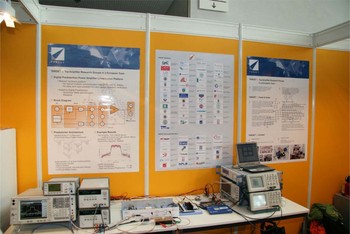
Furthermore, the activities were supported by WP 3.3 “Online and PR”, which took care of additional press coverage (with articles and press releases) and an external newsletter that reaches TARGET-external subscribers (consisting also of an impressive set of major enterprises). Since 2005, TARGET was also present at four major international tradeshows with a booth (at the European Microwave Week and the IEEE-MTTS International Microwave Symposium) to create awareness, to forge new links, and to offer trainings and lab services to the industry.
IV. THE TARGET LAB INFRASTRUCTURE
Immediately after starting TARGET we created a virtual common lab infrastructure within three consecutive work packages. The first of these three, Lab Setup, provided the partners with highly specialized measurement systems and prototype production facilities adapted for shared use with well-defined conditions for access. When exploiting the possibilities of our shared lab infrastructure, we realized that calibration issues of large signal network analyzers (LSNAs) used for the characterization of microwave power transistors were becoming very important. Therefore, the aim of the second work package, Lab Extension, was to continue developing the specific calibration procedures needed for LSNAs in a collaborative way between the partners instead of performing this individually. Based on the results of the first two work packages, the available measurement systems were improved and additional measurement capabilities were set up in the third work package, Lab Future. It was driven by the need for more bandwidth and more sophisticated time domain measurement setups. We have now the possibility to apply an arbitrary stimulus to a system and measure its response. On the one hand, this allows amplifier/system models to be refined which enables, on the other hand, better linearization results. Because the development of models and linearizers is an iterative procedure and cannot be based on a limited set of measurements, it is a huge asset for modeling/linearization groups to remotely access the setup. This allows them to send an amplifier per mail and have access to the measurement system on e.g. a day-by-day basis without the need for traveling each time.
V. SCIENTIFIC WORK PACKAGES
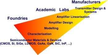
Although being concentrated on microwave PA design, the scientific scope of TARGET was quite larger. As shown in Fig. 3, it stretched from semiconductor devices over their characterization and modeling, amplifier design, linearization issues up to transmitter system design [Reference Devlin, Brazil and Magerl5].
Scientific topics and types of TARGET participants.

In the following we pick two examples of scientific work package groups to show how they were interlinked with each other for obtaining optimum results.
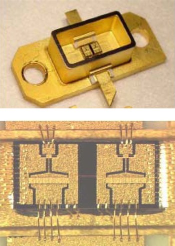
The first group of work packages deals with the design of microwave PAs based on wide band gap active devices. In this context GaN technology is particularly promising. At the beginning of TARGET it was dominated by US and Far East companies. In the meantime European foundries made considerable progress. As shown in [Reference Magerl and Brazil6] they are now among the leading companies. Figure 4 gives an example of a GaN power cell for space applications for operation at 8 GHz with 10W CW output power and power added efficiency of PAE = 35%.
GaN power device for space applications at 8 GHz with output power of 10 W and PAE = 35% (courtesy of Ferdinand Braun Institut für Hoechstfrequenztechnik, Berlin).

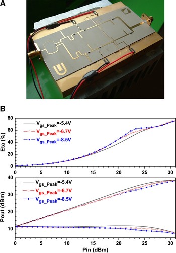
Figure 5 shows an example of a microwave PA based on GaN technology that was provided by Selex Sistemi Integrati. An uneven Doherty amplifier was designed and built showing very interesting results. As can be seen from Fig. 5, at a frequency of f = 2 GHz and output power of 6W it has constant PAE = 50% over a 6 dB back off range [Reference Colantonio, Giannini, Giofrè, Imbimbo, Kompa and Markos7]. This contribution was awarded with the best paper prize of EuMIC 2007.
Uneven Doherty amplifier and its power added efficiency and output power at f = 2 GHz.

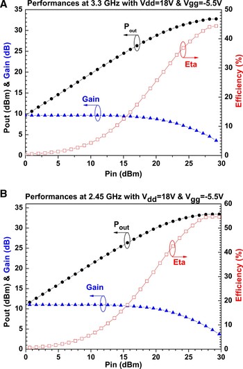
Another highlight of PA design was presented at the 2007 European Microwave Integrated Circuits Conference in Munich [Reference Colantonio, Giannini, Giofrè and Piazzon8]. Figure 6 shows output power, gain, and power added efficiency of a simultaneous dual-band high efficiency harmonic tuned PA in GaN technology at its two design frequencies 2.45 and 3.3 GHz, respectively.
Output power, gain, and PAE of a simultaneous dual-band amplifier at 2.45 and 3.3 GHz, respectively.

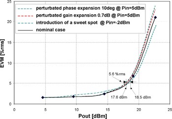
The second example of work packages presented in this report dealt with transmitter system design. The first work package of this group started with the simulation of a commercially available PA at system level, i.e. in its real environment. To this end we co-simulated the PA in a commercial EDA tool along with mixer, VCO, and channel behavioral models. The PA itself was modeled by using a parametric behavioral model capable to tweak important PA parameters, like AM/PM conversion, linearity (sweet spots), and gain expansion. Figure 7 shows the resulting error vector magnitude when tweaking the PA parameters allowing the evaluation of the impact of PA nonlinearities on system performance. This leads to optimum linearity and efficiency by choosing the best tradeoffs of the PA specifications. In this particular case the PA under test is suitable to work in the WLAN TX (lower UNII band) up to P out = 18 dBm.
Error vector magnitude (EVM) depending on output power and on AM/PM conversion of a commercially available PA for WLAN.

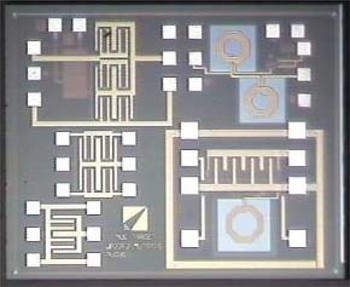
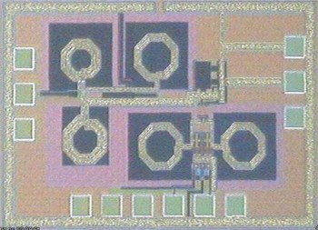
Based on these models we were able to continue to develop basic methodologies at system level for the design of reconfigurable PAs. The result of this second WP was a series of PA prototypes realized in SiGe technology suitable for handheld devices operating at two different communication standards. In Fig. 8 the photograph of the switched matching networks are shown, which were designed by considering tentatively the load-pull values at the frequencies of 2.4 and 3.6 GHz.
Layout of the fabricated test structure MMIC.

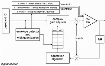
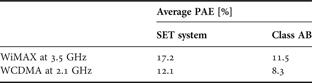
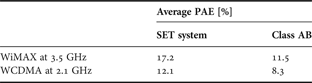
The third WP dealt with the advanced design of monolithically integrated PAs suitable for multiband operation. Wideband Step Envelope Tracking (SET) architecture was realized that increases the average PAE for several signal statistics. As shown in Fig. 9, the dynamic biasing is actuated by comparing the signal amplitude envelope with suitable thresholds. This scheme does not involve any DC–DC converter and inherently includes digital pre-distortion (DPD) algorithms. For testing of the SET scheme two signals were considered: a WiMAX like signal (802.11 g physical layer) and a WCDMA signal. The total power in 20 and 5 MHz bandwidth was chosen as 18 dBm, respectively. As shown in Table 1, the average efficiencies obtained by SET were compared with conventional class AB exhibiting an improvement of 50% under the constraint that the EVM of the WiMAX signal did not exceed the permissible maximum of 5%.
SET scheme providing dynamic biasing of the PA.

Improvement of average PAE by SET.
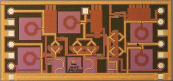
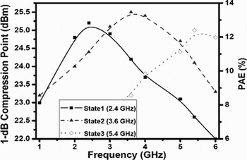
Finally a triple-band PA was designed and a prototype was realized in SiGe technology. The switching between the different output matching circuits is achieved by MOS switches. A photograph of the circuit is shown in Fig. 10; 1-dB compression point and PAE are shown in Fig. 11.
Photograph of multiband PA in SiGe technology with MOS switched output matching networks.

1-dB compression point and PAE of the multiband PA shown in Fig. 10.

In year 4 TARGET moved from integrating its partners along their fields of special interest towards integration in a “horizontal” way. Within the TARGET FUTURE program three work packages were defined that brought together specialists ranging from the fields of semiconductor devices, characterization, modeling, PA design, and linearization up to the system level.
Thus, the work package called “Power Amplifiers: From Semiconductors to Linearised Wireless Systems – WiSeLPAs” started by evaluating the present possibilities of improving the compromise between transmitter efficiency and linearity, identifying to what extent it is now possible to change the device processes and what impact this has on the transistor’s behavioral characteristics. Then, it concentrated on the PA circuit design to generate guidelines for the desirable device process adjustment and PA circuit optimization. Finally, it was devoted to the system-level aspects of transmitter and PA linearization architectures. As an experimental validation step, a hardware test platform, shown in Fig. 12, was designed to develop and implement efficient linearization algorithms and to derive PA specifications for optimal linearization. With these specifications, PAs shall be developed using optimized power devices (for linearity and efficiency) and advanced characterization techniques. Where other visions of wireless transmitter and PA design are concerned, WiSeLPAS investigated the feasibility of nonconventional transmitter architectures that are based on envelope elimination and restoration, but are being integrated with the latest digital techniques.
Photograph of the complete “WiSeLPAs” predistortion hardware test platform as presented at the European Microwave Conference 2007.

The work within the second work package “Multi-Band Transmitters as Allowing Technology for Global Inter-Connectivity and Full-Mobility Systems – MUTATIS” was organized in six major tasks. Task 1 was aimed at identifying the set of system specifications for the entire transmitter along with the definition of the complete description of the environment. Task 2 dealt with the selection of the proper device technology for the development of applications below 6 GHz capable of integrating the best trade-off between power amplification, signal generation and control, and low noise as well as integration of other baseband functionalities. Task 3 was devoted to DPD of multi-band transmitters. A laboratory demonstrator was implemented. In Task 4 a multi-band PA was designed and prototyped in the frame of the TARGET-DeLFI initiative. This amplifier is shown in Fig. 13. Task 5 dealt with characterization, modeling, and EDA analysis of the PA prototypes having two goals in mind. The first is aimed at the extraction of a PA behavioral model. The behavioral model allows the circuit simulation of the complex scenario described in Task 1. The second set of measurements is aimed at the verification of the PA prototype considering large-signal network analysis (LSNA) measurements. Finally, Task 6 – Future Outlook – was devoted to merge all the skills and prospective of the participants in order to define future vision and requirements.
Chip photograph of the SiGe dynamic biasing PA prototype.

The third work package of this series “Hierarchical Study of Millimetre Wave Wideband Wireless Systems – mmWTreeS” was started effectively in March 2007 with the objectives to perform an integrated study on millimetre wave wideband wireless systems and to study one mm-wave system in detail, namely the high-capacity SDH 38 GHz Digital Microwave Radio for Wireless infrastructures. Consequently, the work package was organized in two tasks. Within Task 1 “High-level study on mm-wave telecommunication applications” the topic on mm-wave wideband wireless systems was approached from the two “outer” sides of the TARGET matrix, being the technology part and the system-level part. This task was split into two sub-tasks: study on mm-wave telecommunication applications and study on mm-wave device technologies. Task 2 focused on a particular case study in the 28–38 GHz frequency band. This frequency band is highly important for next-generation networks. There are the broadband local to multipoint distribution systems and multichannel multipoint distribution service planned at 28–30 GHz (Ka band). Next, recent studies recognize the high potential for widespread commercial applications at 38 GHz. Some terrestrial fixed wireless access systems at 38 GHz have already been started in USA and Japan. In this work package, the application under study is high-capacity SDH (from STM1 = 155 Mbit/s up to 4 × STM1 = 625 Mbit/s) 38 GHz Digital Microwave Radio for wireless infrastructures (Cellular Backhaul in mobile broadband systems like 3G and beyond 3G services, i.e. WCDMA and HSPA, and Broadband Fixed Wireless Access Systems).
VI. MANAGEMENT
A key ingredient in the success of a complex structure such as TARGET has been the separation of scientific coordination (by the Vienna University of Technology, Austria) from professional management and administration (by ftw. Telecommunications Research Center Vienna, Austria). The top-level governance structure consists of the Board to decide on all strategic, financial, and contractual issues. The Steering Committee is the central body for the operative project management and implementation of TARGET. It is chaired by the core project management team, i.e. the network and the scientific coordinator. In the bi-monthly meetings, Steering Committee members give account on the work progress, based on the direct reports from work package leaders.
A central instrument was the implemented reporting tool, a proprietary database development. Accessible through the intranet, participants reported their costs every 2 months and described the achieved progress on work package level. This allowed for an up-to-date financial monitoring at any time and also provided various valuable analyses (e.g. deviations from the plan in term of money and/or person months).
Finally, efficient management and fast responsiveness of the project management team contributed to a positive project culture, which in turn was reciprocated by the consortium, thus creating a unique atmosphere of collaboration – the TARGET experience.
VII. TARGET’S BENEFITS
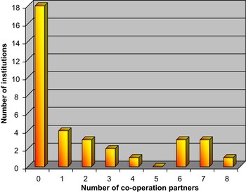
The most important goal of TARGET was to create a durable, co-operative network of partners closely collaborating in the field of microwave PA research. Figure 14 shows that we started with an almost desperate situation. On the y-axis it presents the number of partners that had common research with a given number of other network partners (x-axis) before TARGET. In particular, Fig. 14 shows that 18 partners had no collaboration at all with any other research group of TARGET.
Number of institutions (y-axis) that had a given number of co-operation partners (x-axis) prior to TARGET.

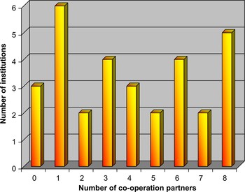
This situation changed dramatically with the creation of our NoE. Figure 15 shows the corresponding figures after 3 years. Now, only three partners stayed by themselves and a multitude of partners had active collaborations outside the WPs with up to eight other TARGET members and even more.
Number of institutions (y-axis) that had a given number of co-operation partners (x-axis) after 3 years of TARGET.

The expertise collected in the NoE TARGET can be put to the best use of industry and students by offering courses and trainings in the fields of
– RF device modeling,
– device-level linearization techniques,
– modeling for TX system-level analysis,
– RF semiconductor materials and devices,
– microwave power amplifier design,
– microwave power amplifier linearization techniques, and
– RF device characterization.
Measurement and fabrication services are available through our different labs participating in TARGET that are dedicated to a certain measurement or fabrication topic. This service is accessible via our home page [9].
ACKNOWLEDGEMENTS
The authors gratefully acknowledge the huge amount of work done by all TARGET partners. We are particularly indebted to all Steering Committee members and to all Work Package leaders for their valuable contributions to TARGET’s scientific and human achievements.
 Gottfried Magerl received the Dipl.-Ing. and Dr.techn. degrees from the Vienna University of Technology, Vienna, Austria, in 1972 and 1975, respectively. From 1973 to 1998, he was with the Institute of Communications and Radio Frequency Engineering, Vienna University of Technology. In 1990, he became the University Professor of Microwave Engineering, and in 1998 he became the Head of the Institute of Electrical Measurement and Electronic Design. He spent the 1981–1982 academic year and the summer months of 1984 and 1986 at the University of Chicago and at Michigan State University, East Lansing, where he constructed high-resolution IR spectrometers based on the microwave modulation of CO2 and CO lasers via the electro-optic effect in CdTe. In the following, his interest in the application of electromagnetic radiation to noncontacting measurement techniques led to the development of a road condition sensing microwave radar and to extensive work on physics and optimization of narrow band atomic line filters. His current research interests concentrate on the development of highly efficient linear microwave power amplifiers for mobile communications. This includes characterization, modeling, and linearization of nonlinear systems without and with memory. From 2004 to 2007 he was a scientific co-ordinator of the European FP6 Network of Excellence called TARGET (Top Amplifier Research Groups in a European Team). Gottfried Magerl is an author and co-author of more than 200 contributions to international scientific journals and conferences. Drawing on his experience as a member of numerous scientific advisory boards of Austrian research funding agencies he is a co-editor of six books on general topics in the field of university and research politics.
 Sue Ivan holds a Master of Science degree in Psychology (1997) from the University of Vienna. She has a track record in the management of extensive, international projects that involve considerable budgets, and worked together with Austrian industry as well as with global players in the following expert topics: cross-national market research, usability of user interfaces and human–machine interaction, and project management of large corporate internet portals. From 2004 to 2007 she was a network co-ordinator and project manager of the European FP6 Network of Excellence TARGET, in charge of coordinating 49 member organizations from academia and industry, and acting as the main interface towards the European Commission. In her role as a funding expert, Sue Ivan is currently responsible for proposal and submission management, and acts as main contact for funding agencies at the Telecommunications Research Center Vienna.