Introduction
Microwave monolithic integrated circuit (MMIC) design involves a few sequential steps. The first and arguably the most critical requirement to start the circuit design is choosing a mature process with high repeatability. After establishing the process, we may proceed to model all MMIC elements, both transistors and passives. A test wafer includes the designed set of test elements, and the set contents depend on the MMIC application (low-noise amplifiers, power amplifiers, switching circuits, etc.). Before the modeling step, the measurement data need to be correctly processed using statistics and de-embedding [Reference Crupi and Schreurs1]. At the final step, models of all elements are compiled to the process design kit (PDK). The described flow is time-consuming and labor-intensive, so its automation is in high demand. Below we provide several examples.
Microwave measurement automation speeds up the process, increases repeatability, and reduces errors. For example, in [Reference Yattoun and Peden2], the authors presented an original load-pull test bench based on a modified active loop technique. The test bench contains a switch between the loop and the pre-matching circuit. The proposed setup is fully automated: calibration, S-parameters, and load-pull measurement with optional pre-matching can be performed without dismantling. In [Reference Boglione, Roussos, Caddemi, Cardillo and Crupi3] a new automatic, highly repeatable, and optimization-less technique for measuring noise parameters of microwave transistors were proposed. In CMOS, statistics is applied to detect bias temperature instability relieving the user from a tedious search of failures in a large amount of data [Reference Saraza-Canflanca, Diaz-Fortuny, Castro-Lopez, Roca, Martin-Martinez, Rodriguez, Nafria and Fernandez4].
Statistical analysis includes outlier detection, measurement data smoothing, and golden device selection. To detect outliers, researchers applied the principal component analysis [Reference O'Neill5], a Mahalanobis distance [Reference Nakamura and Tanaka6], and a convolutional neural network [Reference Chen, Yen, Wen, Yang, Wu, Chern, Chen, Kuo, Lee, Kao and Chao7]. MMIC models are extracted from the golden device's measurements. We determine the golden device as the device having the most ‘average’ characteristics [Reference Saha8]. Wafer Pro (Keysight Technologies) enables calculating the key parameters of the element, a deviation from the mean value, and the criteria that determine closeness to the typical value [Reference Sischka9]. SPAYN software (SILVACO) [10] selects the golden device by calculating the Euclidean distance between average values of device parameters and measured values of each device. The golden device selection is not sufficiently discussed in the literature in the context of RF and microwave transistors [Reference Aoki and Kobayashi11]. Corner-based statistical modeling [Reference He, Victory, Xiao, De Vleeschouwer, Zheng and Hu12–Reference Chen, Xu, Zhang, Chen, Gao and Xu15] is similar to the considered problem. Both tasks deal with parameter variation due to process imperfection. The purpose of each task is to choose a particular device from a batch. In the first one, a typical (golden) device should be identified, whereas in the second one, three devices with the worst (slow), typical, and the best (fast) performance need to be chosen. In the case of advanced statistical modeling, there is a tendency to use TCAD simulation instead of measurements [Reference Vincent, Hathwar, Kamon, Ervin, Schram, Chiarella, Demuynck, Baudot, Siew, Kubicek, Litta, Chew and Mitard16]. Therefore, all the existing golden device selection algorithms and similar approaches consider several independent parameters expressed as real values.
The selected golden device is characterized more thoroughly. Microwave measurement also requires a de-embedding procedure. There are a lot of de-embedding techniques that differ by type of feeding path (coplanar or microstrip), number of de-embedding structures, etc. [Reference Crupi and Schreurs1]. De-embedding techniques remain valid even for state-of-the-art transistors beyond millimeter waves [Reference Deng, Quémerais, Bouvot, Gloria, Chevalier, Lépilliet, Danneville and Dambrine17].
At the next step, the models for all elements of the MMIC are extracted. Automatic extraction techniques for passive and active elements have been developed for several decades [Reference Popov, Bilevich, Salnikov, Dobush, Goryainov, Kalentyev and Metel18, Reference Chen, Wu, Liu, Yin and Kang19].
At the final step, developed models are compiled into a PDK. Besides models, a complete PDK includes parametric cells, process layers, design rule checking, scripts for design automation, etc. There are PDKs for organic electronics [Reference Arnal, Teres and Ramon20, Reference Fattori, Fijn, Hu, Cantatore, Torricelli and Charbonneau21] and three-dimensional nanotube transistors [Reference Srimani, Hills, Bishop, Lau, Kanhaiya, Ho, Amer, Chao, Yu, Wright, Ratkovich, Aguilar, Bramer, Cecman, Chov, Clark, Michaelson, Johnson, Kelley, Manos, Mi, Suriono, Vuntangboon, Xue, Humes, Soares, Jones, Burack, Arvind, Chandrakasan, Ferguson, Nelson and Shulaker22]. In [Reference Arnal, Teres and Ramon20] it is confirmed that efficient PDK development can be achieved by using an automation methodology. Several scripts for controlling the probe-station measurement and extracting the model parameters were developed to characterize a large number of elements.
An overview of papers confirms that the automation of individual steps of PDK development is widely used in scientific and industrial fields. Automation speeds up a modeling routine and decreases the risk of possible errors as the input data for modeling are usually large.
This article is organized as follows. Section ‘Objective and methodology’ presents objective and methodology. Section ‘Measurement result processing algorithms’ contains a description of the proposed algorithms for golden device selection and noise figure measurement smoothing. Section ‘Experimental validation’ is dedicated to the experimental validation of the proposed algorithms. Section ‘Device manufacturing and measurements’ presents the test transistors and measurement setup. Section ‘Automatic measurement processing’ discusses the application of the proposed techniques to experimental data. Section ‘Small-signal noise modeling’ shows the modeling results obtained with measurement processed using the proposed algorithms. The test amplifier MMICs have been designed to validate model and measurement processing correctness. Sections ‘Amplifier design’ and ‘Measured amplifier parameters’ describe the design and measurement of test amplifiers, respectively.
Objective and methodology
The aim of the presented work is the development of techniques for microwave measurement result processing. The techniques under development should be automatic. Our focus in the paper was on the golden device selection algorithm and the measurement smoothing algorithm. The golden device selection algorithm should use frequency-dependent characteristics such as S-parameters. To test the developed algorithm, we generated a synthetic dataset. In the generated dataset, the golden device and outliers are known. Thus, we can estimate the correctness of the results provided by the algorithm. The second considered algorithm is for measurement smoothing. Several data smoothing algorithms were compared to choose the appropriate one. The test dataset was generated by introducing a random noise to the NF characteristic of the microwave transistor model. The proper algorithm was chosen by calculating the deviation from the original data. The main application of the proposed algorithm is the MMIC PDK development. Therefore, we demonstrate the full MMIC PDK development flow to validate proposed techniques. MMIC PDK usually includes many elements (transistors, lumped passive elements, transmission lines, etc.). However, we limited the modeling examples to microwave transistors – the most sophisticated MMIC elements – for demonstration purposes.
Measurement result processing algorithms
Golden device selection
Usually, when selecting a golden transistor, attention is paid to the set of key transistor parameters. Each parameter in this set (e.g. Idss, Vpinchoff, ft, gain) is represented as a real value, dependent on DC operating point, frequency, or both. In microwave circuit design, frequency characteristics are of the most importance. Therefore, to select the proper device, we should consider the whole operating frequency range rather than several frequency points. In this work, we propose the technique for golden device selection that takes into account both frequency-domain small-signal characteristics (S-parameters, current gain |H21|, maximum gain Gmax, and stability factor K) and key DC parameters. Figure 1 shows a schematic diagram of the proposed golden device selection algorithm.
Golden device selection algorithm.

The proposed algorithm is flexible as it can be run using any number of frequency dependencies and/or real-valued parameters. A concrete parameter set can be chosen concerning the transistor target application. For example, in the present work, we use frequency dependencies (S-parameters, current gain, maximum gain, stability factor) and one real-valued parameter (drain current) to select the golden device for linear (low-noise and buffer) amplifiers. In the case of power amplifiers, one may add several power figures of merit (such as P 1dB, IP3) and exclude noise parameters. Other applications (switch, mixer, etc.) will require sets with different frequency dependencies and real-valued parameters. But to change the target application, it is only needed to correct the selection criteria, and no modifications to the proposed algorithm are necessary.
The algorithm uses a Tukey approach to detect outliers [Reference Tukey23]. This approach is widely used in descriptive statistics. Figure 2 shows a visualization of the Tukey approach using a single frequency point of |S11| from the processed data. Q1 and Q3 stand for the first and the third quartile, IQR stands for the interquartile range.
Outlier detection.

Outliers are detected on each characteristic and each frequency point independently. Transistor sample is detected as an outlier and removed from the set if at least one characteristic contains 5% or more frequency points detected as outliers. This tolerance is added to avoid false detection due to measurement uncertainty. The algorithm should detect only outliers associated with the process variation.
After the outlier has been removed, the algorithm calculates the mean value of each characteristic at each frequency point. Then, a deviation of the i th transistor sample from the mean is calculated for each characteristic on each frequency denoted as X using

where X i is a value for the ith sample, and $\bar{X}$ is the mean value for a certain characteristic at the fixed frequency point.
A linear normalization is applied to compare various characteristics. A normalized deviation of each characteristic at the fixed frequency point varies from 0 to 1. A normalized deviation is calculated as follows:

where D[X]min, D[X]max is the minimum and maximum deviation for a particular characteristic at the fixed frequency point, respectively.
An aggregated normalized deviation summarizes deviations over all the frequency points and all characteristics for a sample of the transistor as follows:

where Err i is an aggregated normalized deviation for ith sample; N is the number of considered characteristics; n is the number of frequency points.
An aggregated normalized deviation shows how far a particular transistor is from the ideal device with average characteristics. A sample with the least value of the aggregated normalized deviation is selected as a golden device for this set.
We generated a synthetic S-parameters dataset to verify the golden device selection algorithm. A small-signal model of the pHEMT with 4 × 50 μm total gate width was used as the base sample with average characteristics. Equivalent circuit element values were changed randomly according to the normal distribution to simulate the process variation. S-parameters were simulated in the 0.1–50 GHz frequency range. We generated 1000 samples where equivalent circuit element values varied within (15% of the mean value). We also generated 10 samples with the element values varied with more than 80% of the mean value to simulate outliers.
As a result, the algorithm found the base sample as a golden device. Also, 161 samples were classified as outliers. Detected outliers included all 10 samples intentionally generated as outliers. Additional 151 outliers appeared due to the synthetic data generation approach. Figures 3–5 show parameters for the synthetic set, where the dashed lines correspond to outliers, gray lines are the set samples, and the solid black line is the golden device.
|S11| for the synthetic data: (a) before removing outliers; (b) without outliers.

|S21| for synthetic data: (a) before removing outliers; (b) without outliers.

|S22| for synthetic data set: (a) before removing outliers; (b) without outliers.

The obtained results show that the proposed technique correctly identified the golden device and outliers. The algorithm execution time is 60 s.
Smoothing the noise figure measurements
Fifty-ohm noise figure is used as the input data for transistor noise modeling. When measuring the 50 ohm noise figure, a transistor is not matched with the source. Hence, high uncertainty is present in the measurement results. Therefore a 50 ohm noise figure plot is not smooth: it abruptly changes at every frequency point. In this case, measurement smoothing may significantly help a modeling engineer to assess the model accuracy in various frequency ranges.
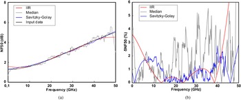
There are plenty of data smoothing algorithms. In this work, we considered the finite impulse response (FIR) filter [Reference Cho24], infinite impulse response (IIR) filter [Reference Kwon, Han, Kwon and Kwon25], median filter [Reference Yin, Yang, Gabbouj and Neuvo26], and Savitzky–Golay technique [Reference Savitzky and Golay27]. We carried out a numerical experiment to choose an appropriate smoothing algorithm. A 50 ohm noise figure was used as the input data. The data were obtained from the noise model of a 0.15 μm GaAs pHEMT with a total gate width of 4 × 50 μm in the frequency range of 0.1–50 GHz. To simulate uncertainty, the input data were multiplied by normally distributed random values with the mean of 1 and the standard deviation of 3σ = 0.5 (see Fig. 6).
Simulated data for the numerical experiment.

In the numerical experiment, we applied each considered smoothing technique to the synthetically generated data. The difference between the smoothed curve and initial data was used to estimate algorithm applicability. Figure 7 shows input versus smoothed data and corresponding relative differences (FIR filter is not provided due to high difference). FIR filter shows a difference of more than 8% over the whole frequency range. The median filter also shows a relatively high difference; however, the mean value of the difference is less than the value obtained for the FIR filter. IIR filter performs well in the middle of the frequency range, but the difference becomes higher at the edges of the range. Savitzky–Golay technique shows the most accurate result, which is also relatively uniform over the whole frequency range. For this technique, the average and maximum differences are 1.5 and 2.5%, respectively.
Input and smoothed data (a); the relative difference between input and smoothed data (b).

As a result, the Savitzky–Golay technique was chosen to smooth the results of the noise figure measurements. This technique demonstrated good accuracy in the numerical experiment. Moreover, it has no input parameters and, therefore, is easy to automate.
Experimental validation
Device manufacturing and measurements
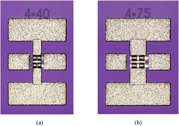
We validated the proposed measurement processing techniques by pHEMT modeling and test amplifier design. The test transistors with a total gate width of 4 × 40 μm and 4 × 75 μm were manufactured using a 0.15 μm GaAs pHEMT process (see Fig. 8). In the present work, we used the well-controlled process. Otherwise, the models would not predict the characteristics of the manufactured devices. PCM tests and several test elements (e.g. transistors) were used to control the characteristics' repeatability.
Microphotographs of test transistors (a) T4 × 40; (b) T4 × 75.

On-wafer measurements of the test transistors at several active biases were carried out in the 0.1–50 GHz frequency range (401 frequency points). For measuring both the 50 ohm noise figure and S-parameters, a microwave vector network analyzer Keysight PNA-X N5247A (0.01–67 GHz) was used. A 50 ohm noise figure was analyzed by the cold-source technique since it is available with the internal impedance tuner (option 029). This VNA option applies a modification of the cold-source technique. The electronic calibration module plays a role of a simple internal impedance tuner. A noise figure measurement with several source impedances allows getting a relatively accurate 50 ohm noise figure of DUT even in the case of a mismatched source. This technique is described in [28].
Seventy-eight samples of the 4 × 40 μm gate width pHEMT and 77 samples of the 4 × 75 μm gate width pHEMT were measured.
Automatic measurement processing
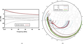
A golden device was selected in 10 s using 12 characteristics (|S11|, |S12|, |S21|, |S22|, Arg(S11), Arg(S12), Arg(S21), Arg(S22), |H21|, Gmax, K, Ids) in the frequency range of 0.1–30 GHz. Thirty-eight samples were classified as outliers. The same task was solved by a modeling engineer manually. The selected device differs slightly from those selected by the algorithm; an engineer's choice has the fourth position if sorted by the aggregated normalized deviation. The measurement on 78 samples of T4 × 75 pHEMT and the selected golden device is presented in Fig. 9.
Measurement on T4 × 75 pHEMT test samples.

The modeling engineer spent more than 20 min which is two orders greater than the execution time of the automated algorithm. The technique deals with all 12 characteristics at all frequency points simultaneously, while a human would hardly pay attention to so many things at the same time. Often one has to process data from four to six wafers with eight different element sizes on average. For each element size, there are up to 100 samples to be measured. Considering the amount of data to be processed, an automatic selection algorithm enables saving much time for the modeling engineer during this predominantly tedious routine.
Fifty-ohm noise figure was measured for the selected golden pHEMTs. Measured data were smoothed using the Savitzky–Golay method; the results are presented in section ‘Small-signal noise modeling’. Open-Short-Pad de-embedding technique was applied to S-parameters. Processed measurements were further used for small-signal noise modeling of the considered pHEMTs.
Small-signal noise modeling
Figure 10 shows a conventional 15-element small-signal noise equivalent circuit (SSEC) used for transistor modeling.
Fifteen-element small-signal noise equivalent circuit of a GaAs pHEMT.

Elements of the SSEC were determined through the combined extraction technique [Reference Popov, Bilevich, Salnikov, Dobush, Goryainov, Kalentyev and Metel18]. Pad capacitances and lead inductances were extracted using the measured S-parameters of the de-embedding test structures (open structure for Cpg and Cpd, short structure for Lg, Ld, and Ls). We used two sets of measured cold FET S-parameters (V ds = 0 V) to extract parasitic resistances: at V gs lower than pinch-off voltage and at zero V gs voltage [Reference Tayrani, Gerber, Daniel, Pengelly and Rohde29]. This cold FET extraction technique is reliable in contrast to the short test structure technique. It allows incorporating the effects of drain and source contact resistances in the small-signal model. After de-embedding extrinsic elements from the measured active bias S-parameters, we extracted all the remaining intrinsic elements by the linear regression technique.
Equivalent noise temperatures of gate-source and drain-source intrinsic resistances were tuned in a circuit simulator to achieve a good agreement between measured and simulated 50 ohm noise figures. It is worth noting that before tuning the equivalent noise temperatures, measured 50 ohm noise figure data were smoothed using the technique described earlier to remove outliers.
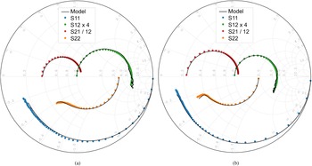
Figure 11 shows the small-signal modeling results for two 0.15 μm GaAs pHEMTs with different total gate widths.
Small-signal modeling results for 4 × 40 μm pHEMT at V ds = 3 V, I ds = 20 mA (a) and 4 × 75 μm pHEMT at V ds = 3 V, I ds = 25 mA (b).

The results of 50 ohm noise figure modeling are shown in Fig. 12.
Fifty-ohm noise figure modeling results for 4 × 40 μm pHEMT at V ds = 3 V, I ds = 20 mA.

The equivalent circuit parameters of the obtained models are listed in Table 1.
Parameters of the small-signal noise models

Obtained small-signal and noise modeling results agree well with the measured data. For any operation point and any frequency, the maximum error of the S12 parameter does not exceed 1.0 dB and 7.6° in amplitude and phase, respectively. Maximum error for the rest S-parameters does not exceed 0.41 dB and 3.3° in amplitude and phase, respectively. A detailed discussion on the kink effect seen in S22 is derived in several papers [Reference Lu, Chen, Chen and Meng30, Reference Crupi, Raffo, Caddemi and Vannini31]. Usually, the effect is attributed to the transition from low-frequency series RC to high-frequency parallel RC in output impedance due to a high transconductance. The combined extraction technique was implemented as an extraction algorithm enabling to build a small-signal noise model in a few seconds.
Amplifier design
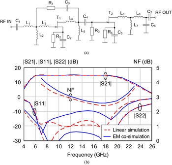
Using the obtained small-signal noise models, we designed two two-stage amplifier test MMICs operating in 7–17 and 17–24 GHz frequency bands, correspondingly. Circuit schematics of the amplifiers include networks for matching, correction, and self-biasing. Figure 13 shows an RF-path equivalent circuit of the 7–17 GHz amplifier MMIC and the results of linear and electromagnetic simulations for the key amplifier parameters. Electromagnetic co-simulation was performed using a planar (2.5D) simulator with 1 × 1 μm mesh in the 0.1–50 GHz range. Two metal layers (Au, 1 and 2.5 μm thin), a dielectric layer (SiN, 0.18 μm thin, ε = 6.5), and a thin resistive film (50 ohm/square) were used for EM co-simulation. We used a 4 × 40 μm gate periphery device in the first stage and a 4 × 75 μm device in the second stage. The parallel feedback was added to the first stage to provide a uniform gain and acceptable input matching in a wide frequency range.
The 7–17 GHz amplifier MMIC: RF-path equivalent circuit (a); results of linear and electromagnetic simulations (b).

Figure 13 (b) shows that gain |S21| and noise figure NF obtained by linear simulation agree well with those obtained by electromagnetic co-simulation. However, an input reflection coefficient |S11| obtained by linear simulation is more optimistic than EM co-simulation results.
Figure 14 shows an equivalent circuit of the 17–24 GHz amplifier MMIC and simulation results of its key parameters. A 4 × 40 μm gate periphery device is used as an active element in both amplifier stages. The results of linear simulation of input |S11| and output |S22| reflection coefficients are also quite optimistic compared to EM co-simulation. Additionally, gain |S21| and noise figure NF, obtained by EM co-simulation, are higher in the low-frequency range.
The 17–24 GHz amplifier MMIC: RF-path equivalent circuit (a); results of linear and electromagnetic simulations (b).

Measured amplifier parameters
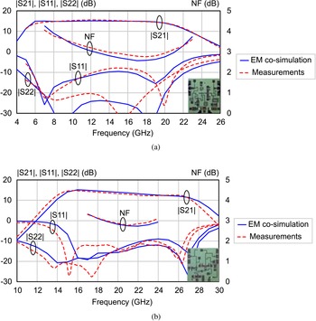
Measured characteristics of the amplifier test MMICs are shown in Fig. 15. Required, simulated, and measured key amplifier parameters are listed in Tables 2 and 3. Obtained experimental data agree well with EM co-simulation results. It confirms that obtained small-signal noise models are valid in a wide frequency range. A set of PCM tests was used to control the test amplifiers' manufacturing process. Additionally, test transistors were manufactured on the wafers. According to measurements, deviations of test transistors' parameters from the golden device parameters are within the permissible process variations.
Measured characteristics of the amplifier test MMICs, operating in 7–17 GHz (a) and 17–24 GHz (b) frequency bands.

Parameters of 7–17 GHz amplifier (5 V, 45 mA): requirements, simulation, measurements

Parameters of 17–24 GHz amplifier (5 V, 30 mA): requirements, simulation, measurements

Conclusion
The paper considers the techniques for selecting a golden device of the wafer and smoothing the measurement results. These measurement result processing techniques are preliminary steps in the modeling of microwave transistors and other MMIC elements. It is reasonable to automate these steps as they require processing a large amount of measured data. The proposed algorithm of golden device selection performs up to 100 times faster than a modeling engineer. In the case of a microwave transistor, to select a golden device, one usually has to process data from four to six wafers with eight different element sizes where up to 100 samples of the same size can be measured. Moreover, the data for passive MMIC elements should also be analyzed. Therefore, the total volume of measured data to be processed is enormous. Applying an automatic selection algorithm enables saving much time for the modeling engineer during this predominantly tedious routine.
The most significant result of the present work is the developed technique for golden device selection. Table 4 shows a comparison of the considered task and very similar approaches for corner-based statistical modeling.
Corner modeling and golden device selection tasks examples

Experimental validation of the proposed techniques was carried out by modeling the microwave transistors and designing the test amplifier MMICs. Small-signal noise models of the 0.15 μm GaAs pHEMTs with 4 × 40 μm and 4 × 75 μm total gate widths were developed. These models were used to design two test amplifiers operating in 7–17 and 17–24 GHz frequency bands. The agreement of measured and simulated characteristics demonstrates the validity of the modeling flow and confirms the applicability of the proposed data processing techniques.
Therefore, existing techniques use a set of real value parameters to select a typical or corner device. To the best of the authors' knowledge, the technique for golden (typical) device selection using a frequency dependence of S-parameters is proposed for the first time. Complete automation is the key feature of the proposed technique.
Acknowledgements
This work was funded by Russian Science Foundation (project No 19-79-10036).
 Andrei S. Salnikov received a Ph.D. from TUSUR University. He is currently a head of the 50 ohm Lab of TUSUR University. His research interests are MMIC PDK development, electronic components modeling, microwave circuit automated synthesis.
 Igor M. Dobush, Ph.D., Associate Professor, TUSUR, Senior Researcher at 50 ohm Lab. Research interests: MMIC design, on-wafer measurements, characterization and modeling of RF and microwave components, EDA/CAD tools for microwave devices.
 Artem A. Popov was born in Bratsk, Russia, in 1994. He received the B.S. degree (2016) and M.S. degree (2018) from Tomsk State University of Control Systems and Radioelectronics (TUSUR), Tomsk, Russia. He is currently working toward the Ph.D. degree at 50 ohm Lab TUSUR. His current research interests include compact modeling of microwave and RF compound semiconductor devices.
 Dmitry V. Bilevich, Ph.D. student, TUSUR. He is currently working toward the Ph.D. degree at 50 ohm Lab TUSUR. His current research interests include compact modeling and methods of measurement analysis of the RF structures.
 Aleksandr Е. Goryainov, Ph.D., Associate Professor, TUSUR, Researcher at 50 ohm Lab. Research interests – designing high-performance microwave power amplifiers, automated structural-parametric genetic-algorithm-based synthesis of microwave circuits.
 Alexey A. Kalentyev, Associate Professor, TUSUR, Senior Researcher at 50 ohm Lab. Research interests – EDA/CAD development, automated structural-parametric genetic-algorithm-based synthesis of microwave circuits. More than 90 scientific publications.
 Aleksandr A. Metel, student TUSUR University. He is currently a laboratory assistant at 50 ohm Lab of TUSUR University. His research interest includes MMIC design.