NOMENCLATURE
- g
-
acceleration due to gravity (m/s2)
- m
-
aircraft mass (kg)
- x
-
state vector
-
 $\bf {\dot{x}}$
-
time derivative of the state vector
- u
-
control vector (rad)
- A
-
system matrix
- B
-
control matrix
- F
-
non-linear vector function
- Ixx
-
rolling moment of inertia (kg.m2)
- Lp
-
roll damping derivative (1/s)
- L θ 1c
-
lateral cyclic control derivative (1/s2)
- Mq
-
pitch damping derivative (1/s)
- Mtip
-
tip Mach number
- Mw
-
angle-of-attack stability derivative (rad/s.m)
- Nr
-
yaw damping derivative (1/s)
- u, v, w
-
translational velocities (m/s)
- p, q, r
-
angular velocities (rad/s)
- pss
-
steady state roll rate (rad/s)
- Rrot
-
main rotor radius (m)
- X, Y, Z
-
external forces in body axes (N)
- Xu
-
drag damping derivative (1/s)
- Zw
-
heave damping derivative (1/s)
- γ rot
-
Lock number
- Ω
-
rotorspeed (rad/s)
- Φ, Θ, Ψ
-
Euler angles (rad)
- σ
-
main rotor solidity
- θ0
-
main rotor collective (deg)
- θ 1s , θ 1c
-
longitudinal and lateral cyclic (deg)
- θ diff
-
differential propeller pitch (deg)
-
$\bar{\theta }_{{\it prop}}$
-
mean propeller pitch (deg)
- σ
-
main rotor solidity
- θ tw
-
main rotor twist gradient (rad/m)


1.0 INTRODUCTION
The main rotor of a conventional helicopter is responsible for providing the lifting and propulsive forces of the vehicle. The maximum speed of a conventional helicopter is limited by the main rotor’s aerodynamic characteristics, installed engine power and airframe drag(Reference Leishman1-Reference Newman3). The problems associated with installed engine power and airframe drag can be minimised through careful design, but the primary factor limiting the maximum speed of the helicopter is the main rotor’s aerodynamic restrictions(Reference Johnson2). The first aerodynamic restriction is retreating blade stall. The high rotor loads and increased levels of vibration as the main rotor approaches retreating blade stall can limit the forward flight speed of the helicopter. Another aerodynamic limitation is due to compressibility effects across the advancing side of the rotor disc. In forward flight, the advancing tip Mach number can approach the critical Mach number leading to the formation of shockwaves, which significantly increases the main rotor’s power requirements. These two aerodynamic limitations restrict the maximum speed of the conventional helicopter to approximately 150 Kn(Reference Filippone4), which is a modest flight speed when compared to a fixed-wing aircraft(Reference Leishman1).
There are a number of civil and military applications where vertical take-off and landing capability combined with a high cruise speed would be advantageous, for example, for rapid insertion of troops or ship replenishment missions. Compounding has often been proposed as a solution to increase the maximum speed of the helicopter. There are two common types of compounding known as lift and thrust compounding. The concept of lift compounding is that a wing offloads the main rotor at high speeds, thereby delaying the onset of retreating blade stall. Whereas thrust compounding, which is supplied by a propulsive device such as a propeller, provides additional propulsive thrust in high speed, therefore divorcing the main rotor of its propulsive duties. In order to appreciably expand the flight envelope of a helicopter, the vehicle must be supplemented with both thrust and lift compounding(Reference Johnson2,Reference Sekula and Gandhi5-Reference Buhler and Newman8) . Firstly, consider a helicopter which only features lift compounding. In forward flight, the wing offloads the main rotor thereby reducing rotor loading. However, the main rotor is required to provide the propulsive thrust of the vehicle. Clearly, this type of configuration will not be able to expand the flight envelope of the helicopter, significantly. With a helicopter with only thrust compounding, there is no additional source of lift in forward flight to avoid the main rotor stalling. To avoid the aerodynamic restrictions of the main rotor, thereby expanding the flight envelope appreciably, requires the introduction of both thrust and lift compounding.
The compound helicopter is again being explored as it can potentially satisfy the emerging requirements for the next generation of rotorcraft. The U.S. Army started their Joint Multi-Role (JMR) programme in 2014, which aims to replace their existing fleet with helicopters with greater speed and range capability(Reference Hirschberg9). As a result, some helicopter manufacturers are investigating the compound helicopter design, as it can potentially satisfy the requirements of the JMR programme. For example, Sikorsky has recently concluded their testing of the Sikorsky X2, with the flight tests indicating promising results. The testing of the Sikorsky X2 programme was so successful that Sikorsky has taken this concept to the next level by developing the Sikorsky S-97 Raider®. The Sikorsky S-97 Raider is envisioned to be a multi-role aircraft which can complete various military missions including close-air support and armed reconnaissance. In addition, Airbus Helicopters has flight tested their prototype – the Airbus Helicopters X3. The Airbus Helicopters X3 features both thrust and lift compounding. The wings of the Airbus Helicopters X3 offload the rotor at high speeds and the propellers provide the propulsive force to overcome the airframe drag. The two propellers, which are mounted on either side of the aircraft’s fuselage, provide the yaw control of the vehicle so that a tail-rotor is not required. In high-speed flight, the anti-torque responsibilities are shifted to the fin at the rear of the aircraft which is capable of producing a significant side-force due to the velocity of the local air flow.
Due to the resurgence of interest in the compound helicopter design, various studies have emerged in the literature. The majority of the studies focus on the performance and design of the vehicle. Orchard and Newman provide some insight into the fundamental design of the compound helicopter(Reference Orchard and Newman10). Their study investigated the various design aspects of a compound helicopter such as the wing, rotor and propulsor design. The study suggests that a medium-size wing should be used to provide a compromise between the beneficial effect of offloading the rotor at high speeds and the adverse effect of creating aerodynamic download at low speeds(Reference Orchard and Newman10). Their study also highlights the importance of the wing design to the vehicle, suggesting that an aspect ratio of six would be appropriate so that the wing does not extend into a region where the main rotor’s tip vortex would adversely affect the wing’s performance(Reference Orchard and Newman10). In terms of thrust compounding, Orchard and Newman propose that a ducted fan or a propeller(s) would be the most suitable, in the context of a compound helicopter design, due to their high-propulsive efficiencies in the flight regimes where the compound helicopter is expected to operate(Reference Orchard and Newman10). More recently, Moodie and Yeo(Reference Moodie and Yeo11) conducted a design study of a compound helicopter similar in layout to the Lockheed Cheyenne. Their study focused on the design of a compound helicopter at its cruise condition of 240 Kn. The aircraft was sized to fulfil a mission consisting of carrying 11 troops, a payload of 4,015 lb, to a distance of 424 km from the departure point. Their results reinforce the potential of the compound helicopter and highlight the power benefit from slowing the main rotor at cruise(Reference Moodie and Yeo11). Another potential benefit of the compound helicopter is its ability to carry significant payloads with various studies investigating compound helicopter designs which could carry more than 90 passengers(Reference Yeo and Johnson12,Reference Russell and Johnson13) . For example, Yeo and Johnson performed a parametric design study of a 100,000 lb compound helicopter which was designed to be capable of transporting 120 passengers over a 1200 nm radius(Reference Yeo and Johnson12). Their study focused on a compound helicopter configuration which featured a single main rotor, a wing and two propellers mounted on either side of the fuselage. One of the primary aims of the study was to investigate the effects on blade, disc and wing loading on aircraft performance(Reference Moodie and Yeo11). The study also examined the influence of the rotor blade design, i.e. rotor blade twist, taper ratio of the blades and tip speed, on the cruise performance of the vehicle.
It is clear that there is some literature regarding the compound helicopter; however, the majority of these studies focuses on design and performance. With the renewed interest in the compound helicopter design, there is a need to examine the flight behaviour of this aircraft class. To this end, the aim of this paper is to examine the stability derivatives of a compound helicopter through a comparison with a conventional helicopter. By taking this approach, some stability, handling qualities and design issues associated with the compound helicopter can be identified. To achieve this, two helicopter configurations are considered, namely a conventional helicopter and a compound helicopter. The mathematical models which represent these configurations are linearised around the trimmed condition of steady level flight. By using these linear models, the stability derivatives of each configuration can be extracted and subsequently assessed. The stability derivatives are by their nature one dimensional but do provide some important information regarding the aircraft’s flight behaviour(Reference Padfield14). Although non-linear models play an important role in helicopter flight simulation, one of their drawbacks is that it is difficult to isolate what causes the complex flight behaviour of the aircraft. In contrast, greater understanding of the vehicle’s motion can be obtained by using linear models to analyse the free motion of the vehicle. This is one reason why the non-linear equations of motion are commonly reduced to linear form. The stability derivatives are useful and represent how the helicopter responds following a small perturbation to a vehicle state. Hence, by predicting the stability derivatives of a compound helicopter and comparing them to a conventional helicopter will allow the influence on thrust and lift compounding on the flight behaviour to be isolated.
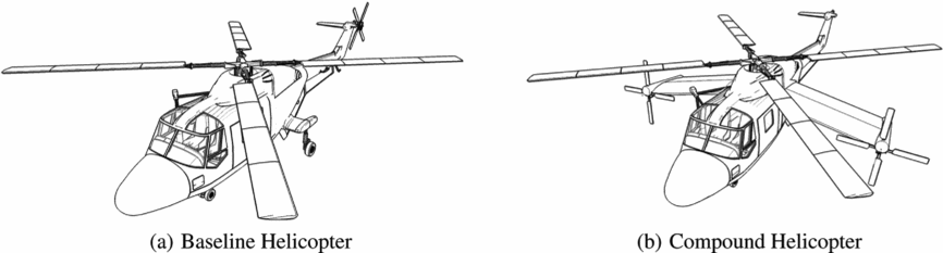
In terms of the modelling approach, the strategy is to use an established mathematical model of a conventional helicopter (in this case, the AgustaWestland Lynx, as shown in Fig. 1(a)), and then convert this model to represent a compound helicopter configuration. The Lynx is referred to as the baseline (BL) configuration throughout the paper and was chosen as the starting point as a well-established data set was available(Reference Padfield14). The compound configuration that is examined in the paper is a similar configuration to the Airbus Helicopters X3 with the preliminary design of the configuration discussed in a previous compound helicopter study(Reference Ferguson and Thomson15). This configuration is named the compound helicopter (CH) configuration, which features a wing and two propellers, as seen in Fig. 1(b). This CH configuration is changed as little as possible, relative to the BL configuration, to allow for a fair and direct comparison between the results of the two configurations. Unless explicitly stated, the design parameters of the BL and CH configurations are identical. The result is a rather unusual looking vehicle Fig. 1(b); however, it should be stressed that this is not a design exercise but a study to investigate the influence of compounding to the stability of the vehicle. Therefore, to ensure that the effects of compounding are isolated from other factors, the basic vehicle shape and size is maintained.
Sketches of the two helicopter configurations.

2.0 METHODOLOGY
2.1 Mathematical modelling
The conventional and compound helicopter models are developed using the Helicopter Generic Simulation (HGS) model(Reference Thomson16). The HGS model is a conventional disc-type rotorcraft model, as described by Padfield(Reference Padfield14), and has found extensive use in studies of helicopter flight dynamics. The HGS model is generic in structure allowing different vehicles to be represented by different parameter sets. The main rotor model, within HGS, ignores the pitching and lagging degrees of freedom, therefore assuming that the flap dynamics have the most influence in terms of the helicopter’s flight dynamic characteristics. The flapping dynamics are assumed to be quasi-steady, a common assumption in main rotor modelling, therefore permitting a multi-blade representation of the main rotor. The main rotor is assumed to be centrally hinged with stiffness in flap and with the main rotor chord assumed to be constant. Furthermore, the model also features a dynamic inflow and a rotor-speed governor model. One important assumption, within the rotor model, is that the aerodynamics are linear, so that the lift is a linear function of the local blade angle-of-attack, whereas the drag is modelled by a simple polynomial. Due to this assumption, non-linear aerodynamics such as retreating blade stall and compressibility are not modelled. To model the non-linear aerodynamics and rotor periodicity requires an “individual blade model,” examples of which are given by Kim et.al, Rutherford, Mansur and Houston(Reference Kim, Celi and Tischler17-Reference Houston20). Regarding the modelling of the other subsystems of the rotorcraft, the forces and moments of the tailplane, fuselage, and fin are calculated using a series of lookup tables derived from experimental data(Reference Padfield14).
One question that naturally arises is the validity of these models and if the results from these rotorcraft models would replicate the real aircraft. In terms of the conventional helicopter, inverse simulation results have shown good correlation for a range of manoeuvres(Reference Bradley, Padfield, Murray-Smith and Thomson21), giving confidence to the worth of the results produced by the HGS model. In relation to the compound helicopter model, a strict validation based on the comparison of flight test with simulation results is not possible, as the appropriate data are not yet openly available. The assumption in this work is that a well-established mathematical model, coupled with validated propeller and wing models will reasonably represent the compound helicopter.
Clearly, there is a need for high-level aerodynamic modelling of the main rotor for certain applications. These types of studies include rotor design, rotor blade dynamics, rotor stability and vibration analysis. In this study, the level of mathematical modelling falls within the Level 1 modelling category of Padfield’s threefold hierarchy of rotor simulation models(Reference Padfield14). Typically, Level 1 rotor models are used for flying qualities and flight dynamics studies(Reference Padfield14). The limitations of a Level 1 main rotor model are well understood(Reference Padfield14) and include the inability to accurately capture off-axis effects. One important limitation of the rotor model is its inability to model non-linear aerodynamics. At very high speeds, it is important to model non-linear aerodynamics(Reference Yeo and Johnson12), such as reverse flow. The current rotorcraft model does not model this non-linear aerodynamic phenomenon and it is reasonable to expect that this limitation could produce unrealistic results at very high flight speeds. Hence, the results in this paper are restricted to speeds under 200 Kn, where the modelling assumptions within the main rotor are still considered valid. Although compressibility effects are not modelled, the issue is attenuated by reducing the rotorspeed of the main rotor of the compound helicopter configuration, above 130 Kn. Note that the rotorspeed of the conventional helicopter is constant throughout the speed range. For the compound helicopter, the reduction of rotorspeed is required as the local Mach number of advancing blade tip would approach unity, if uncorrected, leading to the formation of shock waves, thereby resulting in a significant increase of drag(Reference Anderson22). The end result is that this current work does not assess the flight mechanics of the compound helicopter at the assumed edge of its flight envelope. Although one of the attractive benefits of the compound helicopter is its ability to reach speeds in the region of 250 Kn, it is still important to understand and quantify the flight behaviour of this aircraft between hover and 200 Kn, as the aircraft is likely to operate in this region. By restricting the upper speed limit to 200 Kn, and given the aim of the paper is to assess the broad effects of compounding on the flight behaviour of the helicopter, then it is believed that a Level 1 modelling approach will produce results of sufficient fidelity that reasonable conclusions can be drawn.
2.2 Compound helicopter design
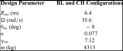
The HGS package is configured to represent the two aircraft configurations featured in this study. As mentioned previously, the conventional helicopter is based on the AgustaWestland Lynx with Table 1 providing some of the important configuration data(Reference Padfield14). Recall that this is not a design exercise, where the compound helicopter’s powerplant and weight are sized to fulfil a particular mission, but a study to examine the effects of compounding on the stability of the helicopter. Hence, to isolate the effects of compounding from other factors, the design changes between the BL and CH configurations are solely due to compounding. As a consequence, the main rotor design of the CH helicopter is identical to that of the BL configuration, as described in Table 1. In terms of the CH configuration it is necessary to size the propellers and wing. Note that the current paper only gives a brief summary of the CH configuration’s design. For a thorough explanation of the CH configuration’s design, the reader is referred to another compound helicopter study(Reference Ferguson and Thomson15). The wing area is selected to be 12 m2, whereas the aspect ratio chosen was six. The choice of wing area is a design compromise between minimising the hover penalty of the wing whilst having the ability to offload the main rotor in high-speed flight. The wing area was determined by examining winged helicopters and forming a statistical relationship between their weight and wing area. The choice of aspect ratio was based on historical data of winged helicopters which have previously flown, which include the NH-3A and SA341 Gazelle helicopters(Reference Frandenburgh and Segel23,Reference Torres24) , leading to the design choice of an aspect ratio of six. The wing’s effective lift vector is placed 0.2 m behind the centre of gravity so that it provides a stabilising contribution to the longitudinal static stability of the vehicle.
Configuration data for the BL and CH configurations

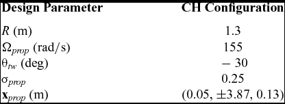
Regarding the design of the propellers, Table 2 shows the chosen design parameters of the propellers. The design of the propellers was driven by the requirement to balance the airframe’s drag at its cruise condition of 200 Kn. The rotational speed is chosen to provide high-velocity airflow over the propeller blades without compressibility effects becoming an issue in high-speed flight. The propeller also features Clark Y aerofoils, which are typically used in propellers. The propellers also feature a high level of twist, 30°, a value which has been used in previous compound helicopter studies(Reference Rutherford18,Reference Kim, Kenyon, Duraisamy and Brown25) .
Propeller design parameters

Due to the introduction of wings and propellers to the CH configuration, it is necessary to account for the greater roll inertia of this vehicle when compared to the BL configuration. The increased roll inertia of the CH configuration is approximated by assuming that the mass of each wing is given by 3.5 lb/ft2 of the wing planform area. This value is used by Stepniewksi and Keys(Reference Keys and Stepniewski26) in their investigation of a winged helicopter. The increase of roll inertia due to the mass of the propellers is estimated by using historical data of propellers and predicting the mass from that information. As a result, the roll inertia of the CH configuration is estimated to be 5357 kg.m2. This is a significant rise from the BL configuration, which is given by Padfield(Reference Padfield14) as 2767 kg.m2.
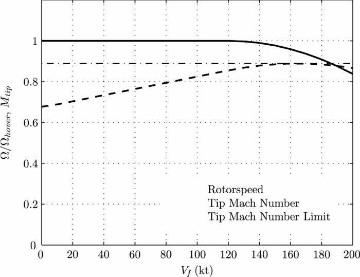
Another design feature of the CH configuration is the variation of rotorspeed with airspeed. In forward flight, it is necessary to slow the CH configuration’s main rotor to avoid compressibility effects. Figure 2 shows how the CH configuration’s rotorspeed varies with airspeed. Note that the rotorspeed of the BL configuration is a constant value of 35 rad/s throughout the flight envelope. In relation to the CH configuration, at 130 Kn the main rotor’s speed is gradually lowered to avoid the assumed drag divergence Mach number. The drag divergence Mach number is the Mach number where the drag coefficient rises significantly(Reference Prouty6). This is commonly defined as the Mach number where the drag coefficient rises at a rate of 0.1 per unit Mach number(Reference Prouty6). Experimental results from various studies confirm that the drag divergence Mach number for typical helicopter aerofoils ranges between 0.85 and 0.92(Reference Sipe and Gorenberg27,Reference Van Dyke28) . The value of 0.89 is selected for this study. At 200 Kn, the main rotor is slowed to 83.8% (see Fig. 2), thereby avoiding an advancing tip Mach number of 0.89. The design decision here is to keep the rotorspeed as high as possible, without compressibility effects becoming limiting, to avoid vibration issues due to the lowering of the blade passing frequency(Reference Orchard and Newman10).
Variation of the CH configuration’s rotorspeed.

2.3 Trim algorithm
Before calculating the stability characteristics, the control angles, which hold the aircraft in a position of equilibrium, at a given flight speed, need to be calculated. Generally, a helicopter can be in trimmed flight when climbing and descending. In addition, the helicopter can also be trimmed whilst in turning flight either with zero sideslip or with zero roll angle. However, in this paper, the trimmed state corresponds to steady level flight with the body accelerations and the attitude rates equal to zero. Concerning the BL configuration, the trim algorithm calculates the four control angles, roll and pitch angles which result in zero translational and angular accelerations acting at the aircraft’s centre of gravity. Essentially, there are six trim targets which are the following:
 $$\begin{equation}
X - mg\,\sin \Theta = 0\\
\end{equation}$$
 $$\begin{equation}
Y + mg\,\cos \Theta \sin \Phi = 0\\
\end{equation}$$
 $$\begin{equation}
Z + mg\,\cos \Theta \cos \Phi = 0\\
\end{equation}$$
 $$\begin{equation}
L = 0\\
\end{equation}$$
 $$\begin{equation}
M = 0\\
\end{equation}$$
 $$\begin{equation}
N = 0
\end{equation}$$
These correspond to the condition of steady level flight. However, the introduction of an extra control(s) to the CH configuration requires a slight amendment to the trim algorithm. The CH configuration features five controls: the main rotor collective θ0, two cyclic controls θ
1s
, θ
1c
, a mean propeller pitch control
 $\bar{\theta }_{{\it prop}}$
and a differential propeller pitch control θ
diff
. The approach taken to trim this aircraft configuration is to prescribe an additional state which results in six unknowns which match the six trim targets, Equations (1)–(6). Presently, the extra state which is prescribed is the pitch attitude, Θ, as it directly impacts the level of thrust that the propellers are required to produce. One possibility is to set a fixed value of pitch to trim the helicopter at all flight speeds; for example, Θ = 0, fuselage level. However, this is not always desirable, as it would require excessive levels of propeller thrusts at certain flight speeds. Another concern is that, in low-speed flight, there is no distinct advantage of having the propellers providing significant amounts of thrust, as it would unnecessarily increase the overall power consumption of the helicopter. Hence, rather than setting the pitch attitude to a fixed value for all flight speeds, a pitch schedule was developed. In low-speed flight, the pitch schedule results in small amounts of propeller thrusts to provide the anti-torque moment. Whereas in speeds in excess of 150 Kn, the pitch attitude is scheduled so that the fuselage is level, which reduces the drag produced by the fuselage. The incidence of the wing is selected so that the lift-to-drag ratio of the wing is maximised at its cruise condition, thereby minimising drag. The assumed cruise condition of the compound helicopter is 180 Kn at an altitude of 1,800 m. These two values have been loosely based on the requirements of the JMR (Joint Multi-Role) programme(Reference Hirschberg9). The selected wing incidence angle at the vehicle’s cruise condition results in the wing providing a significant amount of lifting force whilst retaining an adequate stall margin. Another consequence of this trim approach is that the two propellers provide the majority of propulsive force to overcome the airframe drag in high-speed flight.
2.4 Numerical linearisation algorithm
The non-linear equations of motion need to be linearised to determine the stability and controls derivatives of the vehicle. Generally, there are two methods to linearise the aircraft equations of motion(Reference Padfield14). The first approach is to use a numerical linearisation algorithm which involves the perturbation of the aircraft’s states about the trim condition, thereby allowing the calculation of the stability and control derivatives through numerical differentiation. Conversely, a system identification approach is commonly used to fit a linear simulation model’s response to that of a non-linear model(Reference Tischler and Remple29). The approach used within this paper is the numerical linearisation approach which has been detailed within the literature to assess the stability of both rotary and fixed-wing aircraft(Reference Houston20,Reference Stevens and Lewis30) . The helicopter equations of motion are inherently non-linear and can be conveniently represented in the form
 $$\begin{equation}
{\bf \dot{x}} = {\bf F}({\bf x}, {\bf u})
\end{equation}$$
By using the usual linearisation procedure(Reference Stevens and Lewis30), the linear equations of motion may be written in the short hand form of
 $$\begin{equation}
{\bf {\dot{x}}} = {\bf A}{\bf x}+{\bf B}{\bf u},
\end{equation}$$
where the matrices A and B contain the stability and control derivatives, respectively.
3.0 RESULTS AND DISCUSSION
3.1 Trim results
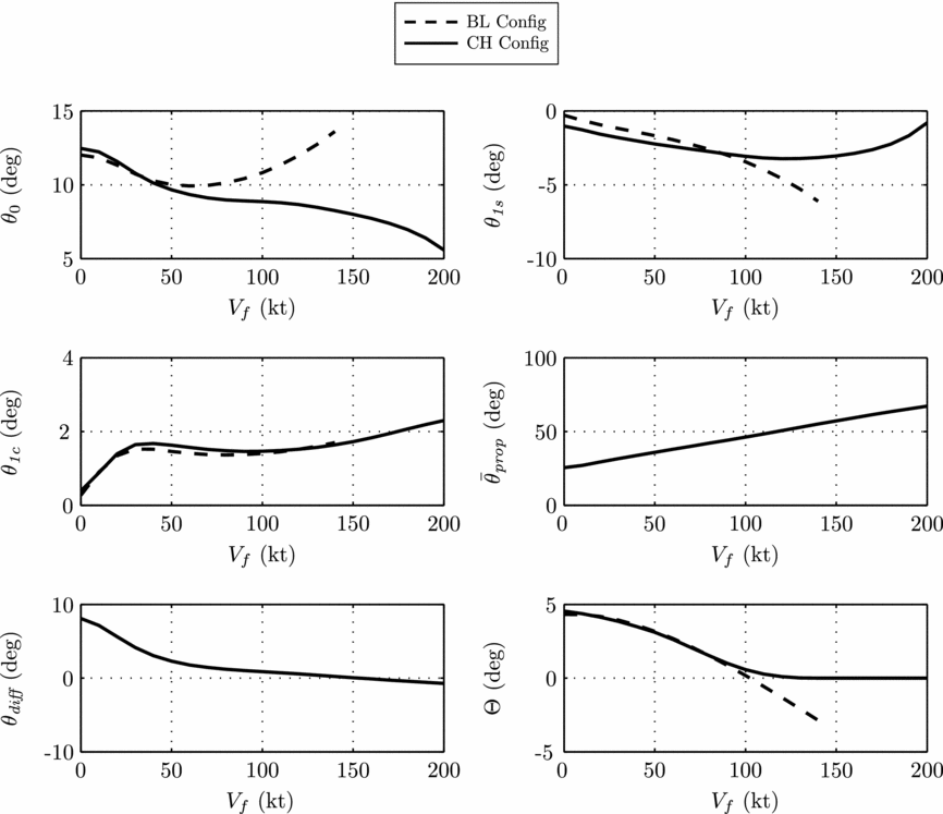
The trim results of the BL and CH configurations are shown in Fig. 3. The first result to note is the difference between the collective settings. In the hover, the increase collective of the CH configuration is due to wake impingement on the wing. This aerodynamic download is captured by the wing’s strip-theory model which uses the main rotor’s uniform and first harmonic inflow terms to estimate the download(Reference Keys and Stepniewski26). As the speed approaches 80 Kn, the collective setting of the CH configuration begins to reduce as the wing begins to offload the main rotor. For the BL configuration, the collective begins to increase above 80 Kn, as the main rotor is required to provide both the lifting and propulsive forces. As the BL configuration approaches 140 Kn, the application of collective and cyclic pitch results in high blade pitch across the retreating side of the disc. For a Lynx-like helicopter, large areas of stall across the retreating side would develop which would be accompanied by high vibration levels above 140 Kn. Recall that blade stall is not modelled; however, care was taken to ensure that both configurations do not reach an unrealistic flight condition. This was achieved by examining the local angles of attack at the outer portion of the rotor discs and checking that they were not above 14°, which would be considered excessive. There is little difference between the longitudinal cyclic values of the two configurations until 100 Kn. However, after 100 Kn, the two propellers begin to supply the propulsive force; therefore, the rotor disc is no longer required to be tilted forward to provide the propulsive force but to balance the pitching moments created by the other aircraft components. The lateral cyclic results of the two configurations are of similar form throughout the speed range. The differential propeller pitch is at its highest in low-speed flight to provide the anti-torque moment. For both configurations, the angle between the vertical fin and the fuselage centre-line is 3°; therefore, the vertical fin offloads the anti-torque device in forward flight. For the CH configuration, the anti-torque moment duties are shifted towards the fin in forward flight, as it provides a side force which results in the propeller differential setting lowering as speed increases.
Trim results of the CH and BL configurations.

One important result from Fig. 3 regarding the CH configuration is the change of θ 1s in high-speed flight. Assuming that the CH configuration features a mechanical flight control system, then for a large part of the flight envelope, the pilot is required to “push” the stick forward as speed increases. It is a handling qualities requirement, which is specified in ADS-33E-PRF(31), that a forward stick motion increases the speed of the helicopter. However, in high-speed flight, the pilot of the CH configuration is required to “pull” the stick backwards above 130 Kn to maintain a trimmed flight condition. This is, of course, a handling deficiency, as pilots generally “pull” the main rotor stick to decelerate. In the case where the compound helicopter features a fly-by-wire control system, then this handling deficiency could be solved with the introduction of suitable control laws. Indeed, it is likely that future compound helicopters will feature fly-by-wire controls due to benefits of reducing weight as well as enhancing the handling qualities of the aircraft.
3.2 Translational velocity derivatives
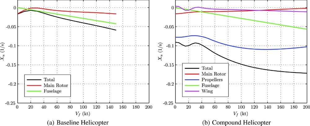
Figure 4 presents the predicted drag damping derivatives of the conventional and compound helicopter configurations as a function of flight speed. For the conventional helicopter, the main rotor and fuselage are the two main contributors to the drag damping derivative (see Fig. 4(a)). For the CH configuration, the predicted drag damping derivative is significantly greater than that of the conventional helicopter’s derivative (see Fig. 4(b)). The addition of the two propellers to the CH configuration has increased the level of drag damping when compared to the BL configuration. A positive perturbation of u reduces the propeller’s thrust, increasing the drag damping of the helicopter. In addition to the two propellers’ influence on Xu , the wing also provides greater drag with a positive perturbation of u, creating greater drag from the wing. The increased drag of the CH configuration, following a perturbation of u, suggests it may be more difficult to accelerate the compound helicopter forward from a trimmed position. However, the response of the vehicle depends on the control sensitivity and control power, in addition to the drag damping. The pilot of CH configuration would be able to accelerate forward by increasing the pitch of the propeller blades which would overcome the increased drag damping of the aircraft. The only handling qualities issue is the task of integrating the propeller pitch control into the pilot’s interface. Having five available controls would undoubtedly increase pilot workload, and therefore isn’t an option. One solution is to introduce a new set of cockpit controls. Examples include a side-stick or a centre-stick interceptor, which would control the pitch of the main rotor and propeller blades. Regardless of the type of pilot interface, the flight control system is likely to be based on fly-by-wire technology, with various control modes. The issue of increased drag damping could be overcome with an attitude/velocity hold response, as discussed by Fletcher et al, in the fly-by-wire upgrade to the UH-60(Reference Fletcher, Lusardi, Mansur, Robinson, Arterburn, Cherepinsky, Driscoll, Morse and Kalinowksi32). In this mode, a forward stick motion increases airspeed and the pilot is able to hold a constant airspeed by re-centring the stick. This control mode would be suitable for the compound helicopter. However, various simulation studies would be required to develop suitable control laws to mix the longitudinal cyclic and propeller pitch controls, so that the vehicle can achieve a smooth acceleration or deceleration by the use of a single control.
The Xu derivatives of the two configurations.

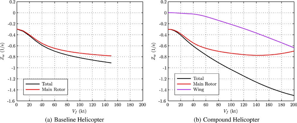
The heave damping derivative, Zw , represents the change of rotor thrust following a perturbation in heave velocity. For a conventional helicopter, the value of the heave damping derivative is dependent on the rotor disc loading(Reference Padfield14). Figure 5 presents the predicted values of Zw for the CH and BL configurations. For the BL configuration, the predicted value of Zw is almost exclusively due to the main rotor contribution, as seen in Fig. 5(a). For the CH configuration, the main rotor’s contribution to Zw decreases in magnitude after 150 Kn due to the reduction of rotorspeed. Also note that after 60 Kn the wing begins to contribute to Zw , as seen in Fig. 5(b).
The Zw derivatives of the two configurations.

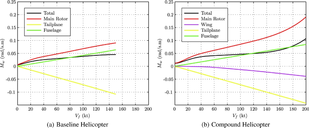
Figure 6 compares the predicted Mw derivatives for the conventional and compound helicopter. The Mw derivative is commonly referred to as the angle-of-attack stability derivative, and for a conventional helicopter, the main rotor’s contribution is generally destabilising(Reference Padfield14). This derivative, Mw , contributes significantly to the longitudinal short period modes of the helicopter and the vehicle’s handling qualities(Reference Padfield14,Reference Blake and Alansky33) . The result here is that the stability derivative Mw for both aircraft configurations is positive, as seen in Fig. 6, throughout the speed range. For the CH configuration, in low-speed flight, Mw is greater than the BL configuration due to the greater rotor loading across the CH configuration’s rotor disc to counter-act the aerodynamic download on the wing. As the CH configuration approaches high-speed flight, the wing begins to contribute to the stability derivative Mw , (see Fig. 6(b)). In this flight regime, where the wing offloads the main rotor, the wing provides a stabilising contribution to Mw as the effective wing lift vector is located aft of the centre of mass. However, the wing’s contribution is still insufficient to ensure that the pitching moment of the entire vehicle is stabilising, following a perturbation of w. In terms of the design of a compound helicopter, it may be necessary to include a larger tailplane than the equivalent conventional helicopter. The size of the tailplane required to improve the handling qualities of the vehicle is discussed later in the paper.
The Mw derivatives of the two configurations.

3.3 Angular velocity derivatives
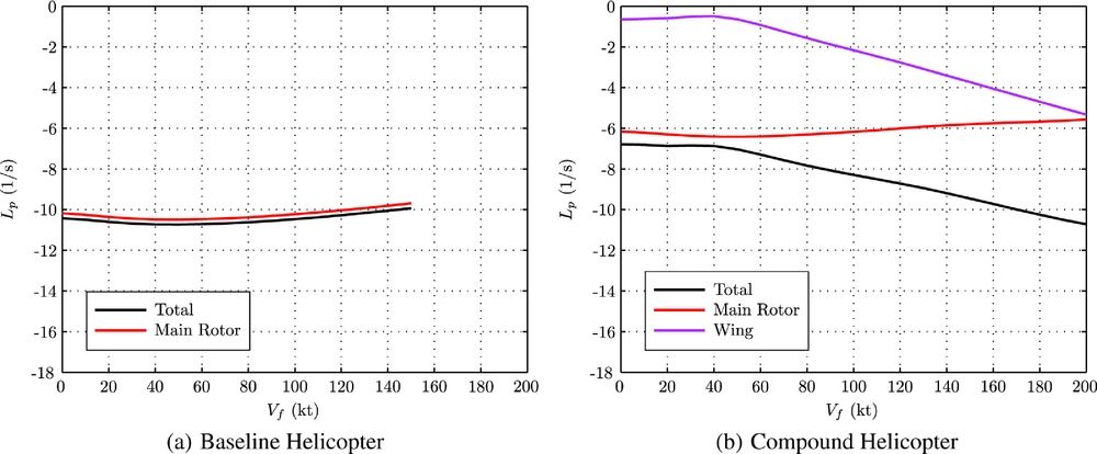
Figure 7 presents the predicted Lp derivatives for the BL and CH configurations. The magnitude of Lp is scaled by the roll inertia, Ixx , of the helicopter. Recall that the roll inertias of the BL and CH configurations are estimated to be 5357 and 2767 kg.m2, respectively. The greater roll inertia of the CH configuration is due to the introduction of the wing and propellers to the design. Figure 7(a) shows that Lp , for the BL configuration, is insensitive to airspeed and is approximately − 10/s across the speed range. The result is consistent with the results produced by Padfield(Reference Padfield14). In contrast, for the CH configuration, the stability derivative Lp is strongly influenced by flight speed. The large change of Lp for the CH configuration across the speed range, as seen in Fig. 7(b), is due to the contribution of the wing. As the wing begins to offload the main rotor, the magnitude of the stability derivative Lp increases, reaching a value of − 10.7/s at 200 Kn. For the CH configuration, the wing’s contribution to Lp is added to the main rotor’s natural tendency to provide a stabilising rolling moment following a perturbation of roll rate, which explains the change of Lp across the speed range.
The Lp derivatives of the two configurations.

The previous result highlighted that when the CH configuration is in forward flight and is subjected to a perturbation of roll rate, then the main rotor and wing produce damping moments. Although the focus of the paper is on aircraft stability, it seems worthwhile to briefly mention the roll response of the BL and CH configurations. Assuming a first-order approximation, the rolling equation of the helicopter becomes
 $$\begin{equation}
\dot{p} - L_{p}p = L_{\theta _{{\it 1c}}}\theta _{{\it 1c}},
\end{equation}$$
where L θ 1c represents the change of rolling moment due to a perturbation of lateral cyclic. By the use of Equation (9), the steady state roll rate due to a one degree step input of lateral cyclic can be shown to be
 $$\begin{equation}
p_{{\it ss}} = -L_{\theta _{{\it 1c}}}/L_{{\it p}}.
\end{equation}$$
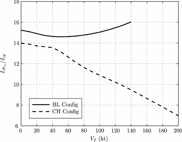
It is therefore interesting to examine the ratio of L θ 1c and Lp for the two vehicles, as shown in Fig. 8. For the BL configuration, the ratio is fairly insensitive to airspeed. In contrast, the ratio for the CH configuration changes across the flight envelope due to the influence of the wing. When the two configurations are subjected to a lateral cyclic one degree step input at 140 Kn, then the steady roll rate of the BL and CH configurations are 16.1 and 9.5 deg/s, respectively. The reduced agility of the CH configuration when compared with the BL configuration is due to two factors. The first factor is the contribution of the wing providing an additional damping moment when the helicopter is perturbed in roll, which is captured by the derivative Lp , as in Fig. 7(b). The second factor is the increased roll inertia of the CH configuration due to the introduction of the wing and propellers to the design.
Ratio of L θ 1c and Lp as a function of airspeed.

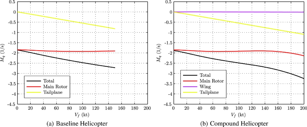
Figure 9 shows the estimated values of Mq for the two aircraft configurations. The BL configuration’s pitch damping derivative changes in a linear manner with flight speed, reaching the value of − 2.7 1/s at 150 Kn. The contribution of the spring stiffness of the main rotor to Mq is constant across the speed range. For this particular derivative, Mq , there is very little difference between the two configurations, as shown in Fig. 9. The addition of compounding, both lift and thrust compounding, does not significantly alter the pitch damping derivative, Mq . As seen in Fig. 9(b), the contribution of the wing to Mq is insignificant due to the small lever arm between the centre of gravity and the wing’s lift vector. In terms of thrust compounding, the effect of a perturbation of pitch rate is minor. For these reasons, the contribution of the propellers to Mq is insignificant. As a result, the main rotor and tailplane are the two primary contributors to the stability derivative Mq for both helicopter configurations.
The Mq derivatives of the two configurations.

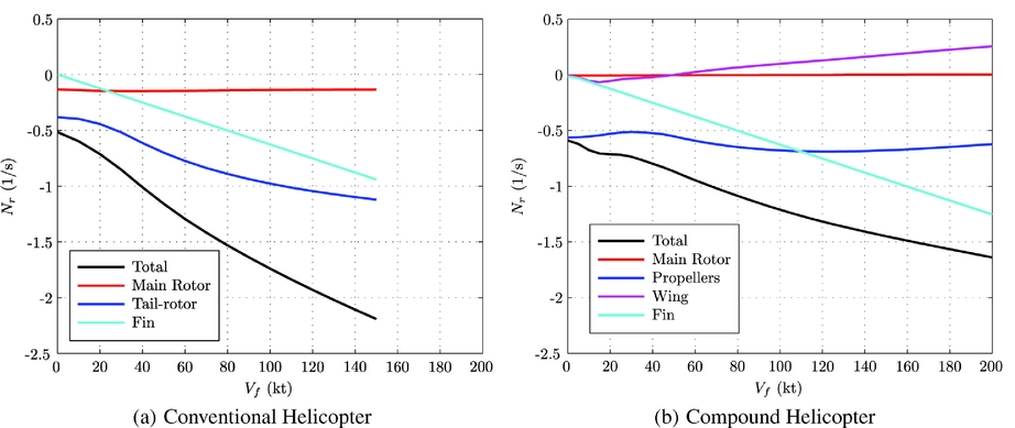
Another important stability derivative is the yaw damping derivative, Nr . This derivative represents the yawing moment following a perturbation of yaw rate with a negative value indicating a stable tendency. The predicted values of the stability derivatives of Nr for the BL and CH configurations are shown in Fig. 10. For a conventional helicopter, the contribution to Nr stems mainly from the fin and tail-rotor located at the rear of the aircraft, as seen in Fig. 10(a). The presence of the tail-rotor in the BL configuration increases the magnitude of yaw damping throughout the speed range when compared to the CH configuration in Fig. 10. Following a positive perturbation of r, the side-force of the tail-rotor increases which slows down the yaw rate of the helicopter, thereby providing a stabilising contribution. The fin also provides a stabilising contribution. The combination of the fin and the tail-rotor provide significant yaw damping for the BL configuration. The CH configuration does not feature a conventional tail-rotor as the anti-torque moment is provided by differential thrust from the two propellers mounted on either side of the fuselage. The two propellers provide a stabilising contribution to the yaw damping derivative, Fig. 10, which is fairly constant across the speed range. Following a positive perturbation of yaw rate, r, the thrust of the starboard propeller increases, whereas the thrust of the port propeller decreases. As a result, the propellers slow the yaw rate of the CH configuration, as seen in Fig. 10(b). Although the propellers are not as effective as a tail-rotor in providing yaw damping in forward flight, their contribution is significant. For the propellers, the change of thrust due to a perturbation of yaw rate is proportional to the solidity of the propellers. The solidity of the propellers used in this study is 0.25, which is a high value, but other authors agree this level of solidity is required to avoid propeller blade stalling in high-speed flight(Reference Moodie and Yeo11,Reference Houston34) . This is one explanation why the propellers contribute strongly to the derivative Nr . Although the estimated yaw damping derivative of the CH configuration does exhibit a stable tendency, it may be necessary to increase the level of yaw damping in a compound helicopter design to satisfy the Dutch roll handling qualities requirements specified in ADS-33(31). This question is answered in the following section of the paper.
The Nr derivatives of the two configurations.

3.4 Dynamic stability and handling qualities
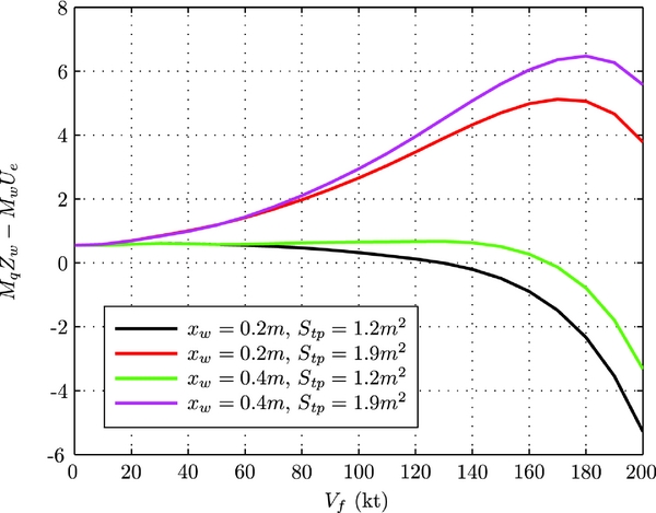
The previous analysis examined the stability derivatives of a compound helicopter and compared them to a conventional helicopter. This analysis highlighted some of the stability issues likely to occur for a compound helicopter. A logical question which arises is how will these stability issues affect the design of a compound helicopter. One key result from the previous analysis is the angle-of-attack instability of the compound helicopter. Handling qualities studies of helicopters have determined that pilots are sensitive to the manoeuvre margin, MqZw
- UeMw
. Blake and Alansky conducted a flight simulation study showing that the handling qualities ratings given by pilots adversely increases when the manoeuvre margin approaches zero(Reference Blake and Alansky33). The margin represents the approximate “spring” term for the helicopter’s short period mode and must be positive for stability. Figure 11 shows how the predicted spring term of the CH configuration changes by altering the position of the wing and the tailplane’s area. The distance xw
represents the distance between the aircraft’s centre of gravity and the effective lift vector of the wing. A positive value indicates that the wing’s effective lift vector is behind the centre of gravity position. The term Stp
represents the area of the tailplane. Note that all four cases have different centre of gravity positions to reflect the type of CH configuration. For example, in the case where the wing maintains its original position but the tailplane size has been increased by 60%, the centre of gravity position has been shifted 17 cm rearward to accommodate for the additional weight of the tailplane. With the size of the AgustaWestland Lynx’s original tailplane,
 $1.2\text{\,m}^2$
, and the lift vector located 0.2 m behind the centre of gravity, the spring term reaches zero at 128 Kn. Maintaining the same size of tailplane but moving the wing’s lift vector further aft results in the manoeuvre margin equalling zero at 167 Kn. Therefore, with the original tailplane size, the longitudinal handling qualities of the CH configuration would degrade in forward flight. By increasing the tailplane area by 60% to
 $1.9\,\text{m}^2$
, the manoeuvre margin is positive throughout the speed range (see Fig. 11). Increasing the tailplane area has a greater affect than moving the wing’s lift vector rearwards because it has a favourable contribution to both Mq
and Mw
. In contrast, the wing’s position does little to influence the pitch damping derivative.
Spring term of the short period mode.

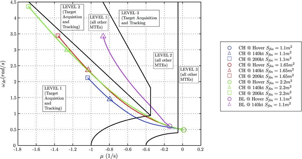
Another issue which has been previously highlighted was the reduction of yaw damping for the CH configuration due to the absence of a tail-rotor. This derivative influences the Dutch roll mode of the helicopter. Figure 12 presents the variation of the damping and frequency of the CH configuration’s Dutch roll mode with vertical fin area. Also shown is the ADS-33 specification boundaries for the two main classes of MTE, known as “target acquisition/tracking MTEs” and “all other MTEs.” In this analysis there are three vertical areas which are considered. The first area,
 $1.1\text{\,m}^2$
, corresponds to the size of the BL configuration’s fin, and another two cases were
 $S_{{\it fin}} = 1.65\text{\,m}^2$
and
 $2.2\text{\,m}^2$
. Also shown in Fig. 12 is the Dutch roll mode of the BL configuration. In the hover, it is predicted that the Dutch roll modes of all CH configurations fall into the level 3 category and are neutrally stable. The absence of a tail-rotor is the reason for this result. However, as the CH configurations transition into forward flight, the stability of the Dutch roll mode improves. Consider the BL and CH configurations with the same vertical fin areas of
 $1.1\,\text{m}^2$
at 140 Kn. The frequency of the BL configuration’s mode is more than double of that of the CH configuration. This is due to the greater weathercock stability of the BL configuration, captured by the derivative Nv
, which is mainly due to the contribution of the tail-rotor. The real part of these two eigenvalues at 140 Kn is very similar, meaning that the Dutch roll mode of both configurations has a comparable time to half amplitude. However, the reduced frequency of the CH configuration’s Dutch roll mode places it into the level 1 category at 140 Kn, for target acquisition/tracking tasks. In fact, all of the CH configurations fall into this handling qualities level in forward flight (see Fig. 12). This is due to the propellers’ contribution to Nr
, which shifts the eigenvalues to the left of the frequency/damping plane due to the greater relative damping. For the two cases where the fin area is increased, by 50% and also 100%, the Dutch roll mode of the CH configuration conforms to the level 1 handling qualities criterion, for all MTEs, at the airspeeds of 48 Kn and 38 Kn, respectively. It is also interesting to note that in forward flight, the damping ratios of all CH configurations are comparable. The results suggest that the CH configuration would not require a larger vertical fin to conform to the level 1 handling qualities for target acquisition/tracking tasks across the majority of the flight envelope.
Comparison of Dutch roll mode for different vertical fin areas.

CONCLUSIONS
The aim of this paper was to examine the stability derivatives of a compound helicopter through a comparison with a conventional helicopter. By taking this approach some stability, handling qualities and design issues associated with the compound helicopter could be identified. The following is a list of conclusions from the work:
-
1. The bare airframe CH configuration has negative speed stability above 130 Kn.
-
2. The compound helicopter design will have greater drag damping when compared to a conventional helicopter of similar shape, size and mass.
-
3. Due to the introduction of lift compounding, the roll damping derivative changes with airspeed. The main conclusion here is that the roll damping from the wing and the increased roll inertia of the CH configuration reduces the roll agility of the helicopter.
-
4. The results indicate that the tailplane area of the bare airframe CH configuration would need to be increased by 60% to stabilise the manoeuvre margin.
-
5. The Dutch roll mode of the CH configuration is predicted to be neutrally stable in the hover. In forward flight, the Dutch roll mode of the bare airframe CH configuration falls into the level 1 category for target acquisition/tracking MTEs. The results suggest there may be no need to increase the vertical fin size of the CH configuration.
ACKNOWLEDGEMENTS
The authors would like to acknowledge the Scottish Funding Council (SFC) for providing the funding, under the GRPE Scholarship, to conduct this research.