Introduction
The mechanical response of most engineering metals subjected to abrupt, dynamic loads is dictated by the behavior of dislocations. The strain rate is related to the density of gliding dislocations, denoted N m, through the Orowan equation [Reference Orowan1].
 $${\dot{\varepsilon }^{\rm{p}}} = {{{N_{\rm{m}}}b\bar{v}} \over M}\quad ,$$
where b is the Burgers vector,  $\bar{v}$ is the mean velocity of gliding dislocations, and M is the appropriate Taylor factor. Constitutive theories that connect the density of mobile dislocations and their associated mean velocity are able to reproduce most salient features of dynamic deformation in metals, despite neglecting microstructural features such as grain size.
As grain sizes approach the nanocrystalline regime, approximately 10–100 nm, the volume fraction of grain boundaries and material near grain boundaries is significant. In conventional nanocrystalline materials, grain boundary motion via sliding, shuffling, and diffusion can account for a significant portion of plastic deformation. The increased role of grain boundary–mediated plasticity with decreasing grain sizes has been provided as a rationale for the higher strain rate and temperature sensitivity observed in nanocrystalline FCC metals than their coarse-grained counterparts [Reference Conrad2, Reference Wei, Cheng, Ramesh and Ma3, Reference Argon and Yip4, Reference Dao, Lu, Asaro, De Hosson and Ma5, Reference Wei, Bower and Gao6]. Even at cryogenic temperatures, where diffusional processes are frequently suppressed, grain boundary motion is still observed in nanocrystalline Cu [Reference Zhang, Weertman and Eastman7].
Recently, a new class of stable nanocrystalline alloys has been developed, wherein grain boundaries are intentionally pinned by solute clusters of large atoms [Reference Koch, Scattergood, Darling and Semones8, Reference Darling, Roberts, Mishin, Mathaudhu and Kecskes9, Reference Darling, Huskins, Schuster, Wei and Kecskes10]. Unlike pure nanocrystalline metals, grain boundaries in stable nanocrystalline alloys remain pinned up to a significant portion of the melting temperature [Reference Frolov, Darling, Kecskes and Mishin11, Reference Koju, Darling, Solanki and Mishin12]. Accordingly, plastic deformation by grain boundary motion is suppressed. Because grain boundary motion is suppressed, these materials exhibit lower rate and temperature sensitivity compared to pure nanocrystalline metals [Reference Darling, Rajagopalan, Komarasamy, Bhatia, Hornbuckle, Mishra and Solanki13]. In pure nanocrystalline and coarse-grained metals, a rapid increase in flow stress is observed for loading rates exceeding 104–105 s−1 [Reference Regazzoni, Kocks and Follansbee14]. However, in stable nanocrystalline materials, no such increase in flow stress, and therefore strain rate sensitivity, is observed for loading rates up to 105 s−1 [Reference Turnage, Rajagopalan, Darling, Garg, Kale, Bazehhour, Adlakha, Hornbuckle, Williams, Peralta and Solanki15].
Consider a simple relation for the onset of adiabatic shear localization
 $${{{\rm{d}}\sigma } \over {{\rm{d}}\varepsilon }} = {\left. {{{\partial \sigma } \over {\partial \varepsilon }}} \right|_{\dot{\varepsilon },T}} + {\left. {{{\partial \sigma } \over {\partial \dot{\varepsilon }}}} \right|_{\varepsilon ,T}}{{\partial \dot{\varepsilon }} \over {\partial \varepsilon }} + {\left. {{{\partial \sigma } \over {\partial T}}} \right|_{\varepsilon ,\dot{\varepsilon }}}{{\partial T} \over {\partial \varepsilon }} \le 0\quad ,$$
where σ denotes stress and T denotes temperature. When localization begins to occur, the local strain rate within the band increases significantly with respect to small increments in the imposed external strain, i.e.,  ${{\partial \sigma } / {\partial \dot{\varepsilon }}}$ increases. Therefore, materials with lower strain rate sensitivity, given by
 $m = {{\partial \ln \sigma } / {\partial \ln \dot{\varepsilon }}}$, possess lower resistance to shear localization. Experiments have shown that failure strains correlate directly with strain rate sensitivity for most classes of metals [Reference Lin, Hirth and Hart16]. However, stable nanocrystalline materials have been shown to possess better resistance to shear localization than their pure nanocrystalline counterparts despite their lower rate sensitivity [Reference Wei17, Reference Darling, Tschopp, Guduru, Yin, Wei and Kecskes18]. Existing constitutive models that describe the high-rate behavior of nanocrystalline materials do not provide a rationale for these observations.
In the present work, the basic unit process of high-rate dislocation motion in stable nanocrystalline metals is re-examined in the context of dislocation elastodynamics. Key effects of transient wave propagation on the stress state in adjacent grains are studied in the context of strain rate sensitivity and propensity for strain localization. Nanocrystalline Cu–10 at.% Ta with an average grain size of 50 nm is used as a model material because it has exhibited the aforementioned properties of thermally stable nanocrystalline materials [Reference Darling, Huskins, Schuster, Wei and Kecskes10, Reference Darling, Rajagopalan, Komarasamy, Bhatia, Hornbuckle, Mishra and Solanki13], although conclusions in this work can be generalized to other stable nanocrystalline alloy systems.
Dislocation kinetics
In thermally stable nanocrystalline alloys, where grain boundary mediated plasticity is not significant, deformation occurs by the motion of dislocations and other defects. For the purposes of this work, the focus will be on dislocation-mediated plasticity, although in the Cu–Ta system, a small volume fraction of twins have been observed [Reference Bhatia, Rajagopalan, Darling, Tschopp and Solanki19]. However, these twins do not contribute significantly to the overall plastic deformation.
In pure, coarse-grained metals, the mean free path of gliding dislocation, denoted as  $\bar{x}$, is determined by the spacing of complex, energy-minimizing dislocations structures [Reference Clifton, Burke and Weiss20, Reference Kocks, Argon and Ashby21, Reference Kuhlmann-Wilsdorf22]. As the material is strained further and more dislocations are created,
 $\bar{x}$ decreases. The mean velocity is then dictated by the time it takes to glide between and overcome these obstacles, such that
 $$\bar{v} = {{\bar{x}} \over {{t_{\rm{w}}} + {t_{\rm{r}}}}}\quad ,$$
where t w and t r are the waiting and running times between obstacles.
Most approaches describe waiting at obstacles as a thermally activated process, whereas running between obstacles is described using a viscous drag relation, where the viscosity B increases as the dislocation velocity approaches the shear wave speed [Reference Taylor23]. Relations for the change in the density of gliding dislocations have been proposed to include multiplication by interaction and formation of sources [Reference Johnston and Gilman24], nucleation from stress concentrations [Reference Gupta, Duvall and Fowles25], statistical annihilation [Reference Roters, Raabe and Gottstein26], and trapping into sessile arrangements [Reference Kuhlmann-Wilsdorf22], giving
 $${\dot{N}_{\rm{m}}} = {\dot{N}_{{\rm{mult}}}} + {\dot{N}_{{\rm{nuc}}}} - {\dot{N}_{{\rm{ann}}}} - {\dot{N}_{{\rm{trap}}}}\quad ,$$
where subscripts denoted the multiplication, nucleation, annihilation, and trapping rates, respectively. The number of mobile dislocations generally increases with increasing plastic strain and strain rate, although the strength increase can be attributed to the increase in the total number of dislocations, both mobile and immobile. Because  $\bar{v}$ can be measured using interrupted tests [Reference Johnston and Gilman27] or simulated with molecular dynamics [Reference Yamakov, Wolf, Phillpot, Mukherjee and Gleiter28], the function describing
 $\bar{v}\left( {\tau ,T} \right)$ is generally assumed to be accurate and the parameters used to describe the evolution of
 ${\dot{N}_{\rm{m}}}$ is fit to experimental data [Reference Clifton, Burke and Weiss20, Reference Jones and Mote29, Reference Johnson, Jones and Michaels30, Reference Austin and McDowell31, Reference Lloyd, Clayton, Austin and McDowell32, Reference Lloyd, Clayton, Becker and McDowell33, Reference Austin34].
For metals with grain sizes less than approximately 100 nm, dislocation structures are not observed to form within grains and, therefore, offer no impediment to motion, e.g., t w → 0. Dislocations are assumed to nucleate at boundaries, glide freely across the grain, and are then incorporated into the opposing grain boundary. The mean free path can be expressed as a function of grain size, and for simplicity, we chose  $\bar{x} \approx {d_{\rm{g}}}$, where d g denotes the average grain diameter. Because the dislocations freely glide across grains without interacting with other dislocations, they cannot form dislocation sources for multiplication, e.g.,
 ${\dot{N}_{{\rm{mult}}}} \approx 0$. When the dislocations impinge on grain boundaries, they can either be incorporated into the boundary as an immobile dislocation, which is described by trapping, or annihilate due to interaction with an opposite signed dislocation. Whether the dislocation is trapped, annihilated, or some combination thereof, it is no longer mobile.
Consider a nanocrystalline material subjected to a constant, macroscopic plastic strain rate  ${\dot{\varepsilon }^{\rm{p}}}$. The instant the material is loaded, the rate of nucleation will exceed the rate of immobilization and annihilation, as initially there are no mobile dislocations. Once the number of mobile dislocations reaches a steady state, e.g.,
 ${\dot{N}_{\rm{m}}} = {\dot{N}_{{\rm{nuc}}}} - {\dot{N}_{{\rm{ann}}}} - {\dot{N}_{{\rm{trap}}}} = 0$, the number of mobile dislocations is related to their nucleation rate and running time via
 ${N_{\rm{m}}} = {\dot{N}_{{\rm{nuc}}}}{t_{\rm{r}}}$. Using these assumptions, the Orowan equation is rewritten for stable nanocrystalline materials as
 $${\dot{\varepsilon }^{\rm{p}}} = {{{N_{\rm{m}}}b\bar{v}} \over M} \to {{{{\dot{N}}_{{\rm{nuc}}}}{t_{\rm{r}}}b\bar{v}} \over M} \to {{{{\dot{N}}_{{\rm{nuc}}}}b{d_{\rm{g}}}} \over M}\quad .$$
The above expression also appeared as an alternative expression given by Orowan [Reference Orowan1], where it is emphasized that this relation for the strain rate is only valid for a constant external strain rate.
Models for dislocation nucleation in coarse-grained and nanocrystalline materials generally employ an athermal threshold stress with some thermally activated term described by an Arrhenius relation [Reference Zhu, Li, Samanta, Leach and Gall35]. Nucleation from grain boundaries occurs at ledges that act as stress concentrations [Reference Van Swygenhoven, Derlet and Froseth36]. A general functional form for equations used to describe the nucleation rate found in literature is  ${\dot{N}_{{\rm{nuc}}}} = \varphi \left( {\tau ,T,{d_{\rm{g}}},{\xi ^i}} \right)$, where τ is the resolved shear stress and ξi represents higher order microstructure descriptors such as grain boundary misorientation distribution [Reference Johnston and Gilman24, Reference Zhu, Li, Samanta, Kim and Suresh37, Reference Zhu and Li38]. At first glance, this implies that while the plastic strain rate
 ${\dot{\varepsilon }^{\rm{p}}}$ depends on the microstructure, it is insensitive to
 $\bar{v}$ once the generation rate of dislocations is equal to the trapping and annihilation rate. In the Methods section, the unit process of a dislocation freely gliding across the grain boundary will be examined in more detail.
Results
Dynamic dislocation stress fields
Consider a dislocation dipole nucleated from a grain boundary located at the origin. The positive edge dislocation moves in the x direction at a specified constant velocity v until it encounters an adjacent grain boundary located at x = 50 nm, while the sessile negative edge part of the dipole remains at the origin. First, the case where the dislocation is trapped at the adjacent grain boundary is examined, followed by the case where it is annihilated within the adjacent grain boundary.
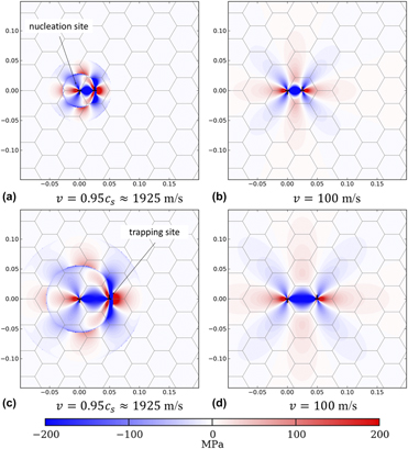
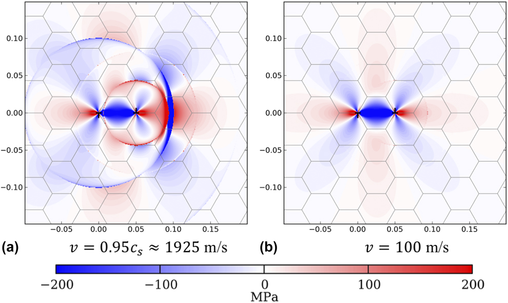
Figure 1 shows the transient shear stresses σxz generated from the injection and glide of the dislocations as they travel across a grain at two specified velocities. For the fast-moving dislocation plotted in Fig. 1(a), where = 0.95c r, two distinct stress domains are present. The first domain, denoted by the outer-most circle, is the portion of the shear stress that travels between c s and c l. The asymmetry of the shear stress in this domain is caused by the mobile dislocation traveling in the x direction. The second domain, denoted by the inner-most circle, corresponds to the part of the shear stress that travels slower than c s. The large amplitude positive shear stress on the right half of this domain is due to the fact that the positive edge dislocation travels at a significant fraction of the shear wave speed, as indicated by its proximity to the inner circle domain wall. For the slow-moving dislocation, plotted in Fig. 1(b) where v = 100 m/s, the transient shear stress field is approximately equivalent to the static solution. By the time the dislocation has traveled half way across the grain, the longitudinal and shear domains have propagated several microns and the transient stress fields have dissipated out to the static solution.
Transient shear stress field σxz for a dipole nucleated at x = 0 with the positive edge dislocation traveling to the right at the indicated velocities. In (a) and (b), the gliding dislocation has traveled half of the way across the grain boundary to x = 25 nm, whereas in (c) and (d), the dislocation has reached the grain boundary at x = 50 nm. Spatial coordinates are in microns (μm).
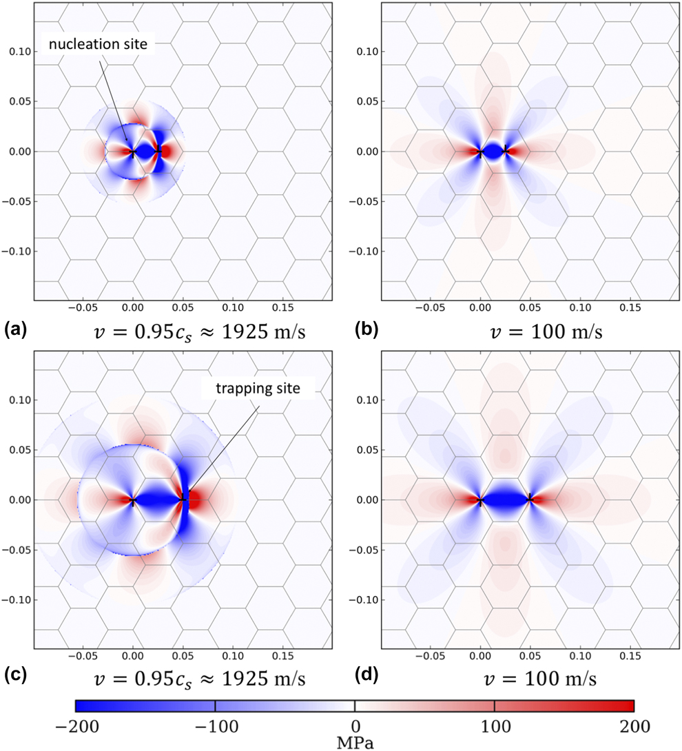
The shear stress field the instant before the fast-moving dislocation reaches the boundary is plotted in Fig. 1(c). By this time, the domains propagating at the longitudinal and shear wave speed have doubled in radius as compared with Fig. 1(a). The magnitude of the positive shear stress ahead of the dislocation has not changed significantly, as stresses continually emanate from the gliding dislocation. The magnitude of the shear stress far away from the gliding dislocation has diminished slightly as the size of the domain affected by the stress increases. For the slow-moving dislocation plotted in Fig. 1(d), there are no remnants of the initial nucleation and the solution is nearly identical to the solution for a static dislocation.
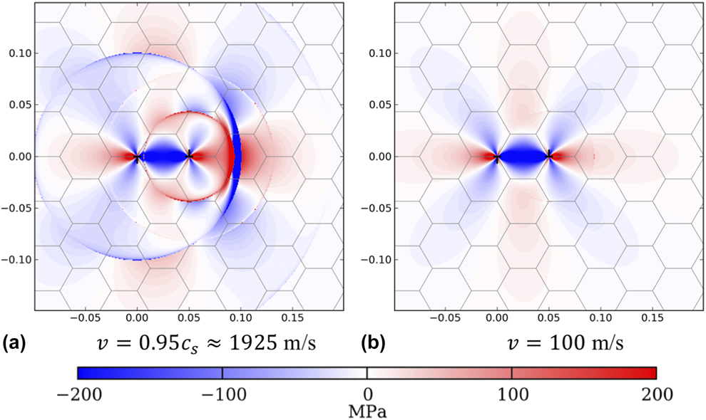
Once the dislocation reaches the grain boundary, it is instantaneously decelerated and immobilized. This deceleration causes the dislocation to emit transient waves that propagate in two domains demarcated by rings that propagate at c s and c l, respectively. The stresses 20 ps after the fast- and slow-moving dislocations have been immobilized are plotted in Fig. 2. The fast-moving dislocation shows two circular domains that have radiated out from the immobilization site and which are the same order of magnitude as the initial waves created during the generation and motion of the dislocation. Comparison of Figs. 1(c) and 2(a) shows that the positive shear stress ahead of the dislocation after it is immobilized are much greater than the stresses when it approaches the grain boundary. The only difference between the static solution and the solution for the immobilized, slow-moving dislocation is that a small disturbance propagating at the shear wave speed is visible. However, the magnitude of this wave is much smaller than the static long range stresses associated with the sessile dislocation dipole.
Transient shear stress field σxz for a dipole nucleated at x = 0 with the positive edge dislocation traveling to the right at the indicated velocities. The gliding dislocation has been rendered immobile at the grain boundary, located at x = 50 nm. The stresses are plotted 20 picoseconds (ps) after the dislocation was immobilized. Spatial coordinates are in μm.
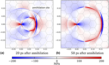
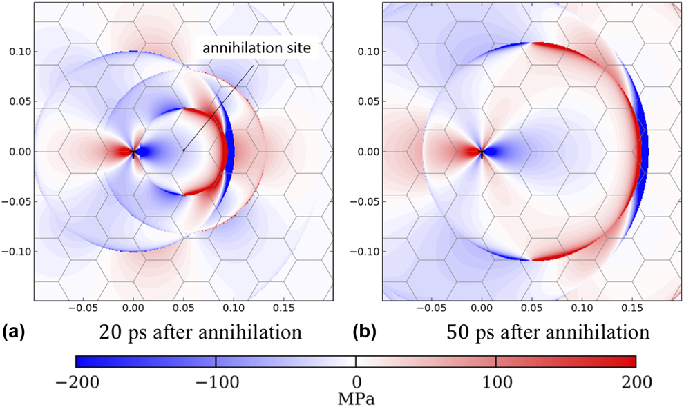
Dislocations that encounter opposite-signed high-energy dislocations within the grain boundary can also be annihilated. Only the fast-moving dislocation is examined because the solution for the slow-moving dislocation is nearly identical to the static solution. Contrasting Figs. 3(a) and 2(a) gives a direct comparison of the stresses associated with annihilation and trapping. The main difference that occurs 20 ps after annihilation is that when the dislocation annihilates, it no longer provides a positive shear stress ahead of the grain boundary. As the time after annihilation increases, e.g., 50 ps after annihilation shown in Fig. 3(b), the domain that has experienced the release wave traveling at the shear wave speed begins to evolve to the static solution for the sessile part of the dipole located at the origin.
Transient shear stress field σxz for a dipole nucleated at x = 0 with the positive edge dislocation traveling to the right at 0.95c r The gliding dislocation has been annihilated at for the indicated time by a grain boundary located at x = 50 nm. Stresses are plotted (a) 20 ps after annihilation and (b) 50 ps after annihilation. Spatial coordinates are in μm.
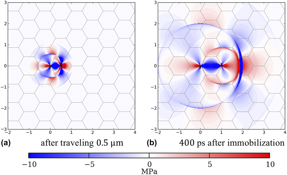
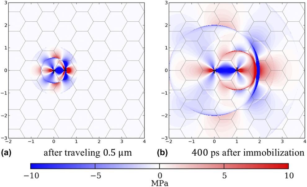
Thus far, the stresses have been discussed for the unit process of a dislocation traveling across a 50 nm grain. Conventional engineering materials have grain sizes on the order of several microns. Additionally, once the grain size reaches the characteristic spacing of dislocation substructure, approximately 1 μm, it is unlikely dislocations will glide freely across the grain without encountering obstacles. As an illustrative calculation, the transient stresses associated with a fast-moving dislocation that travels 1 μm before being trapped are plotted in Fig. 4. The stresses in the scale bar and time that has elapsed after trapping are scaled by a factor of 20 from previous calculations so that the behavior before and after trapping can be compared with nanocrystal calculations in Figs. 1(a) and 2(a). Similar to the static stress field, the transient stress field for dislocations is proportional to 1/d g, which means that the magnitudes of the stresses in Fig. 4 are proportional to the 50 nm case, but scaled by a factor of 1/20. For this idealized case of fast-moving dislocations traveling unperturbed across a 1 μm grain, the magnitude of the transient stresses are fairly small except near the immobilized dislocations. Therefore, transient stresses from fast-moving dislocations in materials with grain sizes exceeding a few hundred nanometers are not expected to affect nucleation differently than static relations used to describe slip transfer criteria in adjacent grains [Reference Lee, Robertson and Birnbaum39, Reference Hunter, Leu and Beyerlein40].
Transient shear stress field σxz for a dipole nucleated at x = 0 with the positive edge dislocation traveling to the right at 0.95c r. The gliding dislocation has been rendered immobile by a grain boundary located at x = 1 μm. Stresses are plotted (a) when the mobile dislocation reaches x = 0.5 μm and (b) 400 ps after annihilation. Spatial coordinates are in μm.
Nucleation stresses exerted on grain boundaries
The previous section included selected plots of spatiotemporal evolution of the transient elastodynamic waves emitted from gliding and stopping dislocations at specified velocities. The total energy E radiated from fast-moving dislocations is well understood from the standpoint of steady-state analysis. Full expressions for the energy are given in [Reference Weertman, Shewmon and Zackay41]. At low velocities, the total energy of a moving dislocation increases linearly with respect to the velocity. As the velocity approaches the shear wave speed, e.g., v → c s, E diverges on the order of E ∝ 1/2β3, where 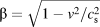 $\beta = \sqrt {{{1 - {v^2}} / {c_{\rm{s}}^2}}}$. An analysis of transient stresses for accelerated edge and screw dislocations are included in [Reference Clifton and Markenscoff42]. Although these simpler analysis methods are useful for determining the effect of velocity on the total energy radiated from moving dislocations, they do not include enough details to determine how these stresses will influence dislocation nucleation. Particularly, for problems such as dislocation motion in nanocrystalline materials, dislocations will not likely achieve steady-state motion for an appreciable duration.
Dislocation nucleation requires a source to be stressed for a finite duration, which introduces a time scale. An approximation for the time it takes to nucleate a dislocation from a Frank-Read source of a specified length l is
 $${t_{{\rm{nuc}}}} = {{l{B_0}} \over {2\tau b}}\quad ,$$
where B 0 is the viscosity [Reference Gurrutxaga-Lerma, Balint, Dini and Sutton43]. For copper single crystals, B 0 has been inferred from experiments to be approximately 70 Pa μs [Reference Greenman, Vreeland and Wood44]. Setting the source length to half the grain size and τ = 0.5 GPa gives t nuc = 6.83 ps. This is likely an upper bound estimate of the duration required for nucleation, since grain boundary sources may occur at ledges or other stress concentrations that are a fraction of the grain dimension [Reference Van Swygenhoven, Derlet and Froseth36].
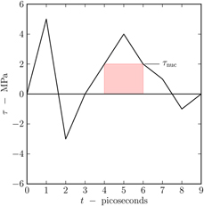
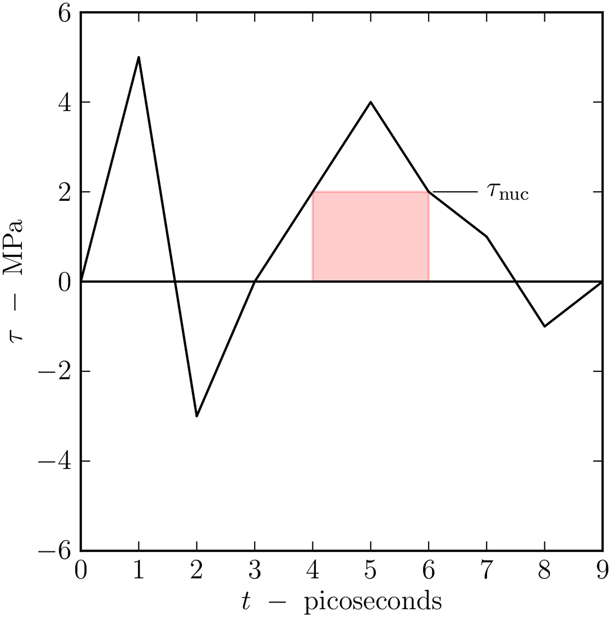
The transient stress that the glide and trapping of a single dislocation contributes to grain boundary nucleation, denoted τnuc, is defined as the maximum finite-duration stress that a grain boundary nucleation source experiences over the course of a simulation. However, the nucleation source must experience this stress for a finite duration, denoted by t nuc. Consider the illustrative example given in Fig. 5 for t nuc = 2 ps. At 1 ps, the nucleation site experiences the largest stress of 5 MPa; however, because the stress drops to 0 at 1.5 ps, a nucleation event could not have occurred over this duration. From 1.5 to 3 ps, the stress becomes negative, but for less than 2 ps before returning to 0. From 3 to 7.5 ps, the stress again becomes positive. In this time interval, the largest stress achieved is 4 MPa, but the largest value the material experiences for a 2-ps duration is 2 MPa. From 7.5 to 9 ps, the stress again becomes negative. The largest stress that the nucleation site experienced for a 2-ps duration over the course of this illustrative example was τnuc = 2 MPa.
Illustrative example showing how τnuc is computed from the given loading history at a nucleation site. In this example t nuc = 2 ps, which gives τnuc = 2 MPa.
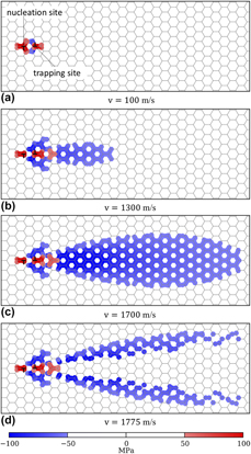
The value of τnuc was computed for a dislocation dipole nucleated at a grain boundary and trapped at an adjacent grain boundary in a regular hexahedral polycrystal with 50 nm grains. Of particular interest is the total length of grain boundaries that are highly stressed due to the nucleation and motion of the dislocation dipole. Post yield behavior in Cu–10 at.% Ta is almost elastic perfectly plastic, and strain hardening does not exceed 100 MPa under compression [Reference Darling, Huskins, Schuster, Wei and Kecskes10]. The transient stress during nucleation is superimposed with the macroscopic shear stress, so a shear stress of 50 MPa would likely activate other potentially active nucleation sites. Therefore, τnuc = 50 MPa was chosen as a cutoff to identify highly stressed grain boundaries. The total length of grain boundaries that experienced a finite-duration nucleation τnuc of at least 50 MPa was plotted for specified dislocation velocities up to the shear wave speed in Fig. 6. Selected plots of τnuc are shown in Fig. 7 at four specified velocities of v, which typify the various behaviors observed for values of v varying from quasistatic behavior up to the shear wave speed.
Total length of grains that experience a nucleation stress of  $\left| {{\tau _{{\rm{nuc}}}}} \right| \le 50$ MPa plotted for d g = 50 nm and specified velocities v. Points correlate with discrete simulations, and a line is included to guide the eye. Contour plots showing spatial distribution of τnuc are included for selected points a–d in Fig. 8.

Contour plot of τnuc that grain boundaries experience in a 50-nm regular hexahedral polycrystal after a dislocation dipole glides across a grain and is stopped at the adjacent grain boundaries at specified dislocation velocities. Plots correspond to points a–d in Fig. 7. Points where  $\left| {{\tau _{{\rm{nuc}}}}} \right| \le 50$ MPa are not shown to ease visualization.
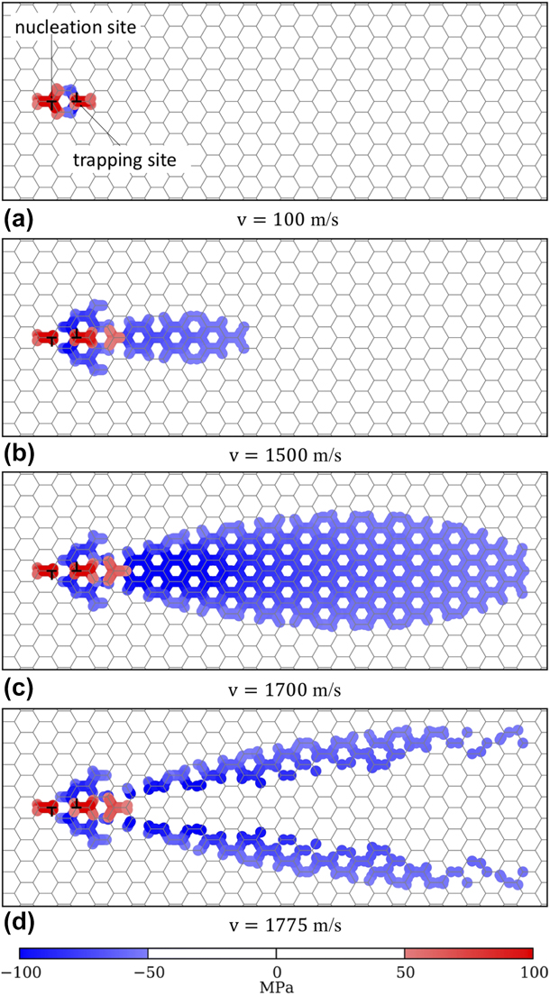
For dislocation velocities up to 1300 m/s, which is approximately two-thirds of the shear wave speed, the length of grain boundary segments that are highly stressed increases approximately linearly with v. Figure 7 shows the grain boundary segments that are highly stressed, as well as their corresponding magnitude and sign. For this range of velocities, only the grain that emitted the dipole and the adjacent grain boundary becomes highly stressed during the nucleation event. The sign and magnitude of the stresses closely resemble the stress state shown in Fig. 2(b), where the stresses generated during the immobilization event are insignificant as compared to the magnitude of stresses due to the static dipole.
When dislocation velocities are increased above 1300 m/s, the length of grain boundary segments that are highly stressed increases rapidly. Figure 7(b) shows the highly stressed regions for a dislocation traveling at v = 1500 m/s. Ahead of the highly stressed region near the grain where the nucleating event occurred, a region appears where grains ahead of the immobilized dislocation experience a large negative shear stress. In Fig. 2(a), these stresses are located at x ≈ 0.1 μm after the immobilization of the fast-moving dislocation. The stresses are the addition of the negative transient stress from the fast-moving dislocation, which propagates at the shear wave speed, and the negative stress generated by immobilizing the dislocation. As the dislocation velocity approaches the shear wave speed, the magnitude of the stress increases. However, the duration of the negative shear front is controlled by the difference in time it takes for the portion of the nucleation stress propagating at the shear wave speed to travel across the grain and the time it takes for immobilization to occur.
The maximum length of grain boundary segments that are highly stressed for finite duration occurs when v = 1700 m/s. In this case, Fig. 7(c) shows that a large region ahead of the dipole experiences a finite duration, negative shear stress. This velocity corresponds to the case where the amplitude of the stress has increased due to the increase in velocity, and the duration is long enough to activate additional nucleation sources. As the dislocation velocity is increased above 1700 m/s, the magnitude of the stress amplitude felt by adjacent grains increases, but the duration of the stress decreases. Correspondingly, the length of grain boundary segments that experience a finite nucleation stress drops rapidly with increasing velocity. Figure 7(d) shows the region of highly stressed grains near the nucleation event remains, but the region ahead of the nucleation event diminishes. By the time v = 1825 m/s, the entire area ahead of the nucleation event that experiences a large negative shear stress for finite duration disappears.
Discussion
Experimentally, it is observed that stable nanocrystalline materials are less sensitive to loading rate than nanocrystalline materials whose grain boundaries are less thermally stable. Furthermore, these materials do not exhibit a strong increase in strain rate sensitivity with increasing loading rate [Reference Turnage, Rajagopalan, Darling, Garg, Kale, Bazehhour, Adlakha, Hornbuckle, Williams, Peralta and Solanki15]. Assuming t w → 0, and the mean velocity of dislocations obeys the linear relation  $\bar{v} = {{\tau b} / B}$, the Orowan equation can be rewritten as
 $${\dot{\varepsilon }^{\rm{p}}} = {{{N_{\rm{m}}}{b^2}\sigma } \over {{M^2}B}}\quad ,$$
where τ = σ/M. Assuming N m is constant would imply that because an increase in rate sensitivity with increasing loading rate is not observed in stable nanocrystalline materials, that the drag behavior described by B, particularly its strong increase as  $\bar{v} \to {c_{\rm{s}}}$, is fundamentally different for these materials than conventional metals. Although this offers a rationale for the observed behavior, dislocation drag may not be the only mechanism controlling high-rate deformation. All plausible mechanisms must be considered [Reference Regazzoni, Kocks and Follansbee14].
Consider the case described by Eq. (7), in which it is assumed the instantaneous structure of the material does not evolve significantly with increasing strain. The plastic strain rate is dictated by the rate of dislocation nucleation. The results from section “Results” suggest that in these materials, fast-moving dislocations exert a transient stress on a finite region near the nucleation event, which increases significantly as v approaches 0.6–0.8 c s. This implies that even if the shear stress required to move dislocations at a significant fraction of c s increases nonlinearly, so does the nonlocal transient stress produced by nucleation of dislocations. Therefore, the functional form for  ${\dot{N}_{{\rm{nuc}}}}$ should be rewritten as
 ${\dot{N}_{{\rm{nuc}}}} = \varphi \left( {\tau ,v,T,{d_{\rm{g}}},{\xi ^i}} \right)$, where elastodynamic calculations of dislocation nucleation inform the functions used to fit observed behavior. Based on these observations, and that it is expected that
 ${\dot{N}_{{\rm{nuc}}}}$ increases substantially at dislocation velocities at velocities lower than those affected by relativistic phonon drag mechanisms, it is hypothesized the transient stresses generated by fast-moving dislocations are likely responsible for the lack of increase in strain rate sensitivity in stable nanocrystalline materials subjected to loading rates greater than 104 s−1.
The range of dislocation velocities required to enhance nucleation agrees with molecular dynamics simulations of nanocrystalline Cu–10 at.% Ta, which showed that for room temperature, high-rate deformation the presence of Ta clusters limits dislocation velocities to approximately 0.5–0.7 c s [Reference Turnage, Rajagopalan, Darling, Garg, Kale, Bazehhour, Adlakha, Hornbuckle, Williams, Peralta and Solanki15]. At elevated temperatures, phonon drag becomes more pronounced and limits the dislocation velocity to velocities where significant enhancement to the nucleation rate is not expected based on elastodynamic analysis. Consequently, a strong increase in flow stress is observed with increasing loading rate at elevated temperatures [Reference Turnage, Rajagopalan, Darling, Garg, Kale, Bazehhour, Adlakha, Hornbuckle, Williams, Peralta and Solanki15].
It is outside the scope of this work to assign a specific functional form of  ${\dot{N}_{{\rm{nuc}}}}$ for Cu–10 at.% Ta with grain sizes on the order of 50 nm, but general features and their departure from pure metals can be discussed. Refined grain sizes are achieved during severe plastic deformation, which creates a large number of high-energy boundaries. Because Ta atoms pin the grain boundaries, the grain boundaries have no mechanism for relieving built up stresses between grains through conventional sliding and recrystallization. The distribution of residual stresses between boundaries will create a much wider range of stresses required to nucleate dislocations at boundaries than in pure metals where stresses can be relieved via thermal relaxation. Accordingly, the results from Figs. 6 and 7 indicate that under high strain rate loading, which occurs due to the imposed strain rate or once a localized band of deformation begins to form and rapidly deform, stresses may activate nucleation sites far from the initial deformation.
If the magnitude of stresses required to nucleate dislocations at boundaries is large compared to the transient stresses, as would be expected in stable nanocrystalline metals, the transient stresses are expected to sample a sufficiently large region to nucleate dislocations at sources that relieves the built up stresses at boundaries. However, if the stress required to nucleate dislocations at boundaries is small, as occurs in pure metals, dislocation nucleation will likely occur near the original nucleation site because this is the most highly stressed region. Therefore, formation of localized deformation should be more difficult in stable nanocrystalline metals where deformation is expected to be more diffuse than in conventional pure metals.
In this work, the Cu–Ta system was used for illustrative purposes, but the behavior of the Cu–Ta system is more complex than the simplified system used to describe high-rate dislocation motion in this work. Ta clusters transition from incoherent to coherent as the amount of Ta is decreased. Molecular dynamics simulations indicate that incoherent clusters promote slip-mediated plasticity, whereas for Cu–1 at.% Ta, the majority of Ta is coherent and promotes deformation twinning [Reference Bhatia, Rajagopalan, Darling, Tschopp and Solanki19]. If deformation twinning is more energetically favorable than dislocation slip, then twin nucleation and growth may govern high-rate plastic deformation instead of slip processes evaluated in this work. Additionally, the clusters induce a misfit strain that depends on the nature of the Ta particles and the applied temperature. The spacing and size of clusters will change the nucleation stress for dislocations and their associated mean velocity and, therefore, the results presented in Figs. 6 and 7. Specific values of mean velocity and nucleation stress can be computed using molecular dynamics simulations [Reference Turnage, Rajagopalan, Darling, Garg, Kale, Bazehhour, Adlakha, Hornbuckle, Williams, Peralta and Solanki15, Reference Chen, Tschopp and Dongare45].
Conclusion
The rapid generation, motion, and trapping of dislocations in stable nanocrystalline metals subjected to high-rate deformation creates significant elastodynamic stresses that propagate to adjacent grains. By examining the magnitude and duration of these stresses, the following conclusions are made:
(1) The nucleation rate of dislocations in stable nanocrystalline metals increases substantially as the dislocation velocity is increased, which provides a rationale for the lack of increasing strain rate sensitivity with increasing strain rate in these materials. This increase in nucleation rate occurs before dislocation velocity is affected by relativistic phonon damping for room temperature deformation.
(2) The resistance of stable nanocrystalline metals to strain localization may be due to the increased area that experiences finite nucleation stresses due to gliding dislocations, leading to diffuse deformation, which is described by elastodynamic considerations provided in this work.
(3) If only the effect of static dislocations is considered, deformation bands would be predicted to form in this high-strength nanocrystalline Cu–10 at.% Ta alloy from coordinated slip transfer across boundaries due to high local stresses in neighboring grains [Reference Lee, Robertson and Birnbaum39, Reference Hunter, Leu and Beyerlein40] or coordinated reorientation of grains [Reference Joshi and Ramesh46, Reference Guo, Li, Pan, Zhou and Wei47].
Method
Dislocation motion treated via elastodynamics
Most treatments of stresses due to dislocations use the solution for static dislocations in the long time limit, i.e., their stresses have been allowed to propagate until they no longer evolve with time. There are two errors with these assumptions. The stress field associated with moving dislocations differs from the stress field of static dislocations, and these stress fields do not propagate instantaneously. As the velocity of a dislocation approaches particular limiting speeds, such as the Rayleigh or shear wave speeds, the shape and magnitude of its stress field changes [Reference Weertman, Shewmon and Zackay41, Reference Eshelby48]. Incorporation of the velocity-dependent solutions into a dislocation dynamics code is straightforward [Reference Van der Giessen and Needleman49]. Although giving a more accurate solution, this quasi-steady approximation still assumes stress fields propagate instantaneously, which is not appropriate for dynamic problems with rapidly evolving dislocation densities. In the case of dynamic deformation in nanocrystalline metals, dislocations are constantly being created, trapped, and annihilated, which will render the quasi-steady approximation inaccurate. Therefore, to capture the time-dependent problem of stress fields propagating from dislocations in stable nanocrystalline materials, a full elastodynamic solution for dislocation motion must be employed.
The time-dependent stress response of dislocations with arbitrary velocity history necessitates an incremental formulation, as each increment in acceleration or deceleration in the velocity history alters the transient stress response [Reference Gurrutxaga-Lerma, Balint, Dini, Eakins, Sutton and Bordas50]. Although lengthy, an analytical expression of the form σ(x, y, t, v) has been derived for a dislocation that is instantaneously accelerated to a constant velocity v [Reference Markenscoff and Clifton51]. Additionally, an equation of the form σ(x, y, t) has been derived for the injection of a static dislocation [Reference Gurrutxaga-Lerma, Balint, Dini, Eakins and Sutton52]. With the superposition of these two solutions, the elastodynamic stresses due to preexisting or injected dislocations that move with constant velocity can be studied analytically, without the need for an incremental, history-dependent formulation.
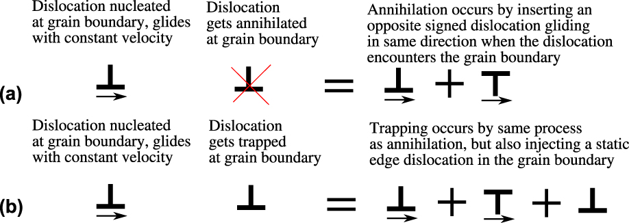
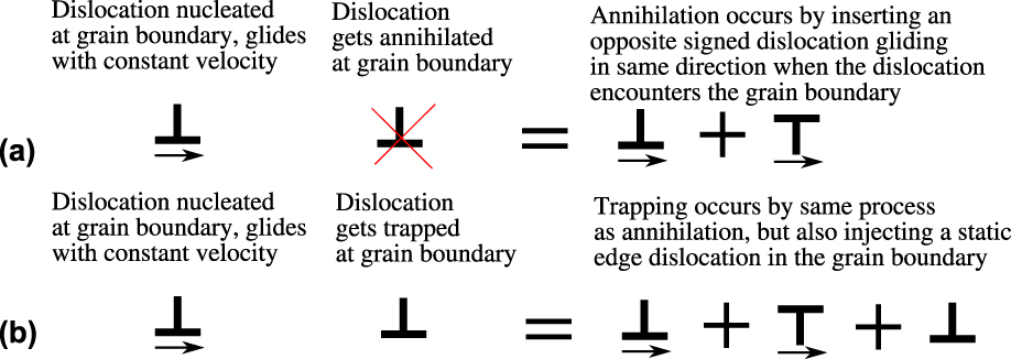
The unit process of a dislocation that nucleates from one grain boundary, freely glides across the grain, and interacts with the adjacent grain boundary is illustrated schematically in Fig. 8. Two scenarios are presented that represent the extrema in behavior. In the first scenario, the dislocation is created from a preexisting source within the boundary, glides across the grain at some constant velocity v, and is annihilated by an opposite signed dislocation within the grain boundary. In the second scenario, the same process occurs, but this time after the dislocation glides across the grain at v, it is trapped within the grain boundary. For this scenario, the long range stress field of the immobilized dislocation is not shielded by its interaction with the grain boundary.
Schematic illustrating how to calculate stresses associated with (a) dislocation annihilation and (b) dislocation trapping at a grain boundary.
In the Results and discussion, illustrative elastodynamic calculations are performed on Cu–10 at.% Ta. Small additions of Ta do not appear to affect the measured value of Young’s modulus for Cu–Ta alloys significantly because the Ta does not exist in solid solution, so a value of 125.6 GPa measured for Cu–3 at.% Ta is used and the Poisson ratio is assumed to be ν = 0.3 [Reference Darling, Kale, Turnage, Hornbuckle, Luckenbaugh, Grendahl and Solanki53]. The density is ρ = 10.1 g/cm3, the Burgers vector is assumed to be identical to that for pure Cu, e.g., b = 0.256 nm, and the average grain size is d g ≈ 50 nm. The elastic properties and density give a Rayleigh, shear, and longitudinal wave speed of c r = 2025 m/s, c s = 2187 m/s, and c l = 4091 m/s, respectively.
Acknowledgments
I wish to thank Drs. Kris Darling and Heather Murdoch for fruitful discussions concerning the behavior of nanocrystalline metals, and Dr. Beñat Gurrutxaga-Lerma for discussing elastodynamic dislocation solutions and their implementation.