1 Introduction
The dynamics surrounding the earliest contact of an impacting drop determines the vigour of droplet splashing and the amount of small bubbles entrained into the pool. Following in the footsteps of Worthington (Reference Worthington1908), drop impact studies have through the decades relied on advances in imaging technology (Etoh et al. Reference Etoh2003; Thoroddsen et al. Reference Thoroddsen, Etoh and Takehara2008). Most early studies have focused on the breakup of the crown (Deegan et al. Reference Deegan, Brunet and Eggers2008), crater formation and collapse (Prosperetti et al. Reference Prosperetti, Crum and Pumphrey1989) or air entrapment under its centre (Thoroddsen et al. Reference Thoroddsen, Etoh and Takehara2003; Hendrix et al. Reference Hendrix, Bouwhuis, Van Der Meer, Lohse and Snoeijer2016). The latest improvements in imaging, which include video cameras with sub-micro-second time resolution (Crooks et al. Reference Crooks, Marsh, Turchetta, Taylor, Chan, Lahav and Fenigstein2013) used herein, as well as high-speed X-ray imaging (Zhang et al. Reference Zhang, Toole, Fezzaa and Deegan2012), are now revealing the finest details of this dynamics.
For medium drop impact velocities on a liquid pool, a prominent feature is the ejecta sheet which is the first stage leading to splashing. It was first revealed in the inviscid numerical simulations of Weiss & Yarin (Reference Weiss and Yarin1999) and observed in the experiments of Thoroddsen (Reference Thoroddsen2002). The breakup of this ejecta sheet produces the splashing of the finest spray, which is important, for example, for aerosol formation. Thoraval et al. (Reference Thoraval, Takehara, Etoh, Popinet, Ray, Josserand, Zaleski and Thoroddsen2012) discovered that the transition to random splashing is associated with Kármán-type vortex shedding from the base of the ejecta, which can destabilize and break it up. This vortex shedding was imaged by Castrejon-Pita et al. (Reference Castrejon-Pita, Castrejon-Pita and Hutchings2012) and Thoraval et al. (Reference Thoraval, Takehara, Etoh and Thoroddsen2013).
Herein, we use an ultra-high-speed video camera to achieve extreme space and time resolution to identify an earlier capillary-driven instability, which forms in the two sharp corners surrounding the base of the ejecta sheet, at impact Reynolds numbers lower than that needed for axisymmetric shedding.
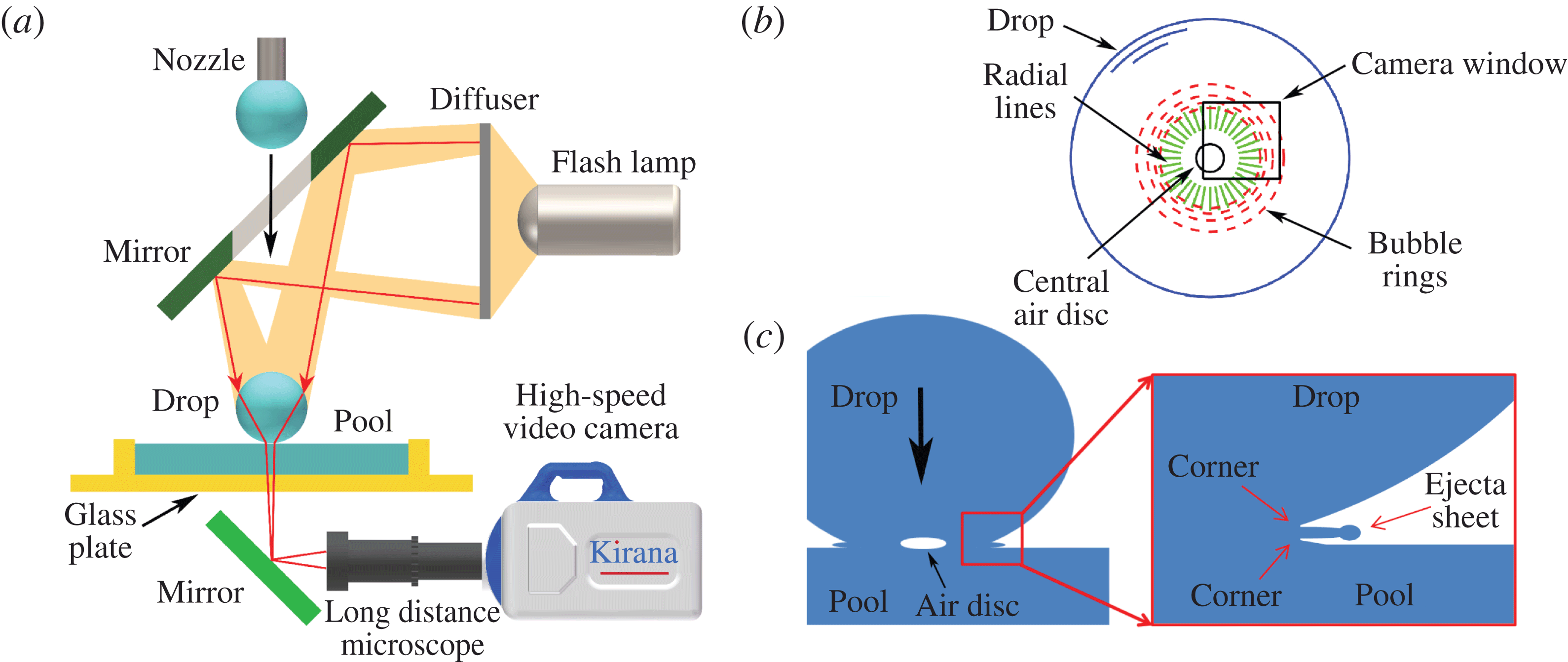
(a) Sketch of the experimental configuration, showing the drop release from a steel nozzle fed by a syringe pump. The drop subsequently falls through a hole in a mirror onto the liquid film contained above a glass surface, with the camera viewing the impact vertically through the bottom. (b) The typical area of the camera view relative to the size of the drop. (c) Sketch of the neck with ejecta and two sharp corners at its base.

2 Experimental set-up
2.1 Imaging set-up
The experimental configuration is shown in figure 1(a) and consists of a drop released from a nozzle and subsequently falling through a hole in a mirror onto the liquid film contained above a glass surface. The mirror allows flash illumination nearly down the vertical axis of the drop. The drop also focuses the light to intensify the light near its centre. The sharp slope of the drop limits imaging near its edge. The camera views the impact through the bottom, using a long-distance microscope (Leica Z16 APO) with adjustable magnification and aperture. Magnifications as large as 29.2 were used, giving a corresponding pixel resolution of up to
 $1.04~\unicode[STIX]{x03BC}\text{m}~\text{px}^{-1}$
. The rapid initial motions were observed with a high-speed video camera (Kirana-05M, Specialized Imaging, Tring UK) at frame rates up to 5 million fps (Crooks et al.
Reference Crooks, Marsh, Turchetta, Taylor, Chan, Lahav and Fenigstein2013). This camera takes 180 frames each with
 $924\times 768$
pixels. Most video clips were acquired at between 0.5 and 2 Mfps, with exposure durations down to 100 ns per frame, to minimize motion smearing. This required intense lighting with a 300 W high-power flash of short duration (
 ${\sim}400~\unicode[STIX]{x03BC}\text{s}$
) (Specialized Imaging, SI-AD 500), which encompasses the entire span of the video clip.
2.2 Liquids and drop shapes
We used common mineral water (Highland Springs) for the drops, while dissolving sodium-chloride (NaCl) to form a salt solution in the film liquid. This generates a strong mismatch in the refractive index, to aid the imaging of disturbances and vortices at the liquid–liquid interface. The pool depth was kept at
 $\simeq 1$
mm by depositing a fixed amount of the salt solution into a circular glass dish containing the bottom pool. This is sufficiently deep to minimize depth effects during the early contact (Thoraval et al.
Reference Thoraval, Takehara, Etoh and Thoroddsen2013). The surface tensions were measured using a ring tensiometer (K100 MK2/SF/C, Kruss GmbH, Hamburg), giving
 $\unicode[STIX]{x1D70E}=71.8~\text{mN}~\text{m}^{-1}$
for the drop and slightly higher value for the salt solution, 73.4 (quarter saturation), 75.0 (half-saturation) and 76.9 (fully saturated)
 $\text{mN}~\text{m}^{-1}$
. Unless otherwise stated, we use the saturated salt solution with a density of
 $1.19~\text{g}~\text{cm}^{-3}$
.
The drop is pinched off from a tapered stainless steel nozzle with a sharp inner edge of
 ${\sim}3$
mm in diameter. The resulting drop is axisymmetric with an equivalent spherical diameter of
 $D=4.23$
mm. The release heights
 $H$
, measured from the nozzle to the pool surface, were varied from
 $H=14.5$
–59.6 cm, giving impact velocities of between
 $U=1.6{-}3.3~\text{m}~\text{s}^{-1}$
. We characterize the impact conditions by the Reynolds and Weber numbers,
 $$\begin{eqnarray}\displaystyle Re=\frac{\unicode[STIX]{x1D70C}DU}{\unicode[STIX]{x1D707}},\quad We=\frac{\unicode[STIX]{x1D70C}DU^{2}}{\unicode[STIX]{x1D70E}}, & & \displaystyle\end{eqnarray}$$
where
 $\unicode[STIX]{x1D707}$
and
 $\unicode[STIX]{x1D70E}$
are the dynamic viscosity and surface tension of the drop liquid. We use the average density of the drop and pool,
 $\unicode[STIX]{x1D70C}$
.
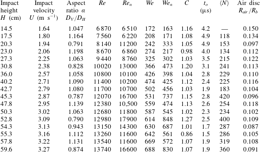
Parameters and experimental results for the various impact release heights.
 $C$
and
 $t_{o}$
are fitting coefficients used in (3.1).
 $\langle N\rangle$
is the average number of radial lines rounded off to the nearest integer. The initial air-disc diameter
 $d_{air}$
is normalized by twice the bottom radius of drop
 $R_{b}$
.

The impact velocities and droplet shapes were measured in a separate set of experiments, as described in the supplementary material available at https://doi.org/10.1017/jfm.2018.383. As the drop is larger than the capillary length for water, significant shape oscillations occur after the pinch off during the free fall. We follow the approach described in Thoraval et al. (Reference Thoraval, Takehara, Etoh and Thoroddsen2013) to characterize the drop shape by an aspect ratio
 $\unicode[STIX]{x1D6FC}=D_{V}/D_{H}$
, where
 $D_{H}$
and
 $D_{V}$
are the horizontal and vertical diameters of the drop at impact. By assuming an elliptic drop shape we can estimate the bottom radius of curvature, as
 $R_{b}\simeq D/(2\unicode[STIX]{x1D6FC}^{4/3})$
. To include this drop shape we therefore define a modified
 $Re_{\unicode[STIX]{x1D6FC}}=Re/\unicode[STIX]{x1D6FC}^{4/3}$
and
 $We_{\unicode[STIX]{x1D6FC}}=We/\unicode[STIX]{x1D6FC}^{4/3}$
. Table 1 lists the various impact parameters used herein.
3 Results
3.1 Speed of neck radius
Having sufficient time resolution we can accurately measure the initial motions of the outer radius of the neck contact
 $R_{n}$
, as is shown in figure 3(a) for typical cases. We plot this radius normalized by the drop bottom radius
 $R_{b}$
, which includes the above aspect ratio estimation,
 $r(\unicode[STIX]{x1D70F})=R_{n}(\unicode[STIX]{x1D70F})/R_{b}$
. Similarly, we normalize the time with an adjustable offset, as
 $\unicode[STIX]{x1D70F}=(t-t_{o})U/R_{b}$
. The simplest possible model of the initial neck motions is based on purely geometric considerations, i.e. that of a sphere cutting a plane, where the intersection moves outwards as
 $\sqrt{2\unicode[STIX]{x1D70F}}$
(Rioboo et al.
Reference Rioboo, Marengo and Tropea2002; Josserand & Zaleski Reference Josserand and Zaleski2003), see also discussion in Philippi et al. (Reference Philippi, Lagrée and Antkowiak2016). However, this model does not satisfy continuity which requires modifying the prefactor. On the other hand, including Wagner inviscid theory for liquid impact on a solid (Wagner Reference Wagner1932; Scolan & Korobkin Reference Scolan and Korobkin2001; Korobkin & Scolan Reference Korobkin and Scolan2006; Riboux & Gordillo Reference Riboux and Gordillo2014; Philippi et al.
Reference Philippi, Lagrée and Antkowiak2016) the radial motions take the functional form
 $$\begin{eqnarray}r(\unicode[STIX]{x1D70F})=C\,\sqrt{3\unicode[STIX]{x1D70F}},\end{eqnarray}$$
where theoretically
 $C=1$
. Here we use
 $C$
and
 $t_{o}$
as fitting coefficients, which are listed in table 1 for all of the impact heights. The value of
 $C$
is close to unity, with an average of 1.07, which supports the validity of (3.1) above. The significant spread in the values of
 $C$
are likely caused by the drops being an elliptic paraboloid resulting in
 $C(\unicode[STIX]{x1D6FC})$
, as can be inferred by theoretical considerations (Scolan & Korobkin Reference Scolan and Korobkin2001; Oliver Reference Oliver2002; Korobkin Reference Korobkin2007). However, to characterize this
 $C(\unicode[STIX]{x1D6FC})$
one would need high-resolution concurrent measurements of the drop shape from a second side-view video camera.
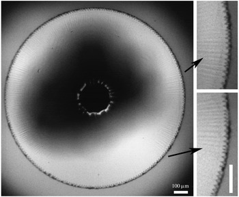
Regular teeth in the neck connecting the drop to the pool, with radial lines extending from these teeth into the interface between the drop and pool liquid. For
 $U=2.71~\text{m}~\text{s}^{-1}$
,
 $\unicode[STIX]{x1D6FC}=1.09$
, giving
 $Re_{\unicode[STIX]{x1D6FC}}=10\,200$
and
 $We_{\unicode[STIX]{x1D6FC}}=425$
. Outside this circle the drop has not yet contacted the pool. The central irregular circle is the outer edge of the entrapped air disc. Keep in mind that the drop diameter,
 $D=4.23$
mm, is three times larger than the width of this image. The darker section in the middle of the image arises from the hole in the mirror, through which the drop falls. Both scale bars are
 $100~\unicode[STIX]{x03BC}\text{m}$
long.

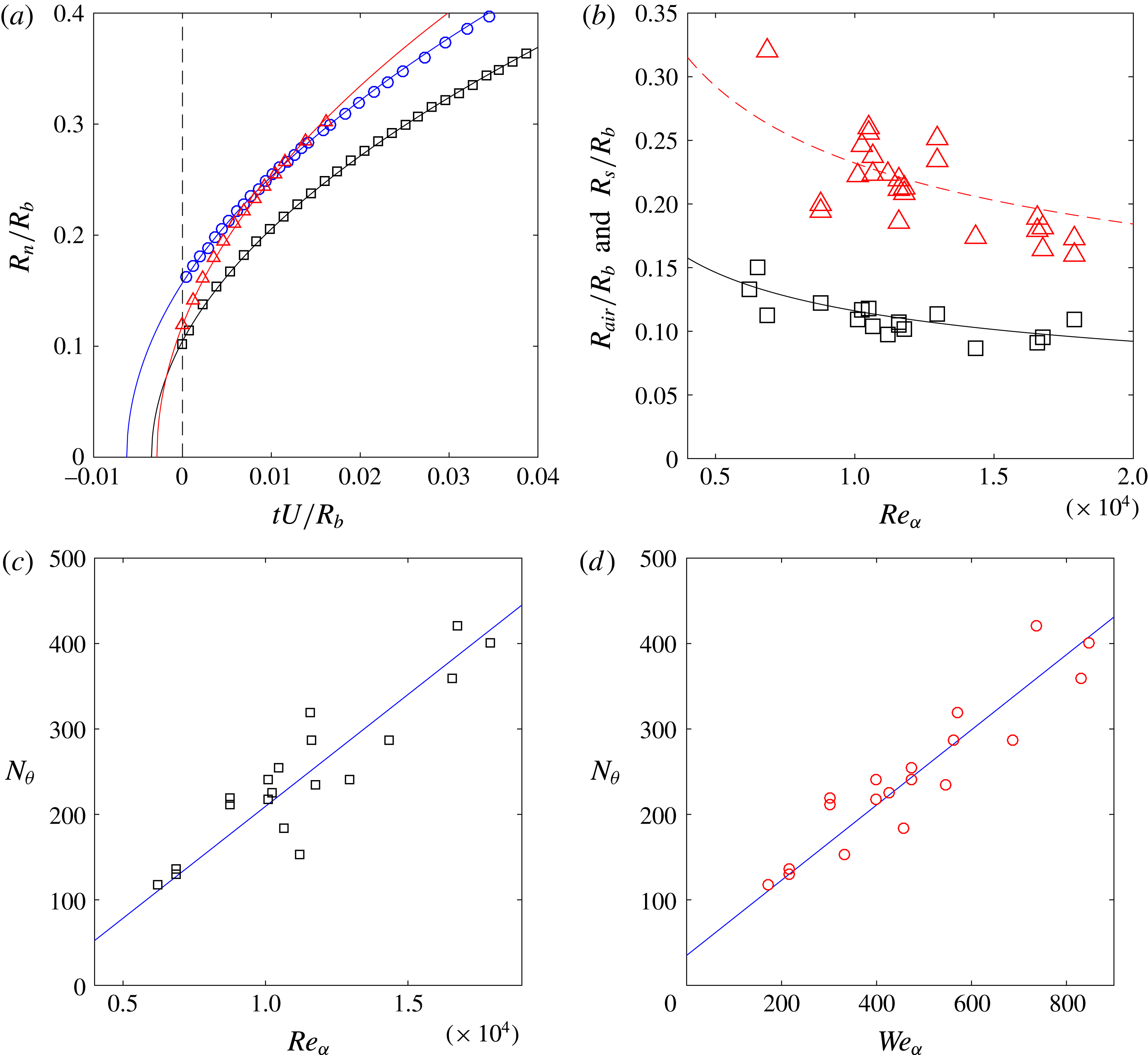
(a) The radial motion of the outer edge of the neck contact, for
 $U=1.64~\text{m}~\text{s}^{-1}$
,
 $Re_{\unicode[STIX]{x1D6FC}}=6510$
(blue circle);
 $U=3.02~\text{m}~\text{s}^{-1}$
,
 $Re_{\unicode[STIX]{x1D6FC}}=11\,800$
(black square);
 $U=3.09~\text{m}~\text{s}^{-1}$
,
 $Re_{\unicode[STIX]{x1D6FC}}=17\,900$
(red triangle). Solid lines are fits using (3.1), with coefficients given in table 1. (b) Size of the central air disc (black squares) and radius
 $R_{s}$
at onset of radial lines (red triangles). The black curve corresponds to (3.2), with
 $C_{2}=1.35$
, while the top dashed curve shows double this radius, with
 $C_{2}=2.70$
. (c,d) Total number of radial lines around the periphery, versus
 $Re_{\unicode[STIX]{x1D6FC}}$
and
 $We_{\unicode[STIX]{x1D6FC}}$
. Keep in mind that both
 $R_{b}$
and
 $U$
change for these data, as listed in table 1.

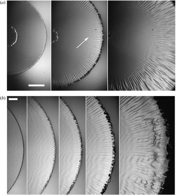
The evolution of the edge instability and radial lines, for (a)
 $U=3.02~\text{m}~\text{s}^{-1}$
,
 $D=4.23$
mm and
 $\unicode[STIX]{x1D6FC}=1.063$
, giving
 $Re_{\unicode[STIX]{x1D6FC}}=11\,800$
and
 $We_{\unicode[STIX]{x1D6FC}}=545$
. Frames shown 10, 20 and
 $70~\unicode[STIX]{x03BC}\text{s}$
after first contact. The scale bar is
 $200~\unicode[STIX]{x03BC}\text{m}$
long. (b) Evolution of the front, for
 $U=2.38~\text{m}~\text{s}^{-1}$
,
 $\unicode[STIX]{x1D6FC}=0.828$
, giving
 $Re_{\unicode[STIX]{x1D6FC}}=13\,000$
and
 $We_{\unicode[STIX]{x1D6FC}}=473$
. Times shown at
 $t=16$
, 22, 24, 31,
 $56~\unicode[STIX]{x03BC}\text{s}$
from first contact. Scale bar is
 $100~\unicode[STIX]{x03BC}\text{m}$
long. See supplementary movies 1 and 2.

The full Navier–Stokes simulations of Thoraval et al. (Reference Thoraval, Takehara, Etoh, Popinet, Ray, Josserand, Zaleski and Thoroddsen2012) of the initial neck radius versus time are in perfect agreement with (3.1), showing (after modifying the notation)
 $r(\unicode[STIX]{x1D70F})=1.004\sqrt{3\unicode[STIX]{x1D70F}}$
.
The initial velocity of the neck is therefore
 $\text{d}R_{n}/\text{d}t=C\sqrt{3R_{b}U/4(t-t_{o})}$
. For the largest
 $Re_{\unicode[STIX]{x1D6FC}}$
this speed is
 $54~\text{m}~\text{s}^{-1}$
, or
 ${\sim}17$
times the impact velocity, which is significantly faster than the ejecta sheet
 ${\sim}10$
(Thoroddsen Reference Thoroddsen2002), which emerges later on.
3.2 Onset of front instability and radial lines
Figure 2 shows the regular teeth-like pattern in the neck region connecting the drop to the pool liquid. Here the distance between the adjacent teeth is
 ${\sim}17~\unicode[STIX]{x03BC}\text{m}$
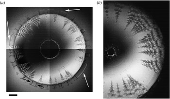
and they are seen around the entire periphery. The image shows radial lines extending from these teeth into the liquid in the neck. These lines are visible through the index of refraction difference between the drop and pool liquids, manifesting localized vertical motions which we associated with streamwise vorticity. Each radial line may consist of two counter-rotating streamwise vortices. We infer the presence of these vortices by their subsequent sideways interactions, as is evident in figure 4(a).
These frontal undulations appear when
 $Re\sim 7000$
and
 $We\sim 200$
. For lower impact heights the front remains straight, as shown in supplementary figure S3. This is not a sharp boundary and weak undulations can occur at larger radii, for lower
 $Re$
, as was shown in Thoraval et al. (Reference Thoraval, Takehara, Etoh and Thoroddsen2013), but no well-defined teeth appear.
Figure 3(b) shows the initial radius of the central air disc
 $R_{air}$
. This disc has been extensively studied, especially for drop impacts on a solid surface, see Josserand & Thoroddsen (Reference Josserand and Thoroddsen2016). This entrapment is characterized by balancing the viscous lubrication pressure in the air with the drop inertia, giving rise to the Stokes number
 $St=\unicode[STIX]{x1D707}_{g}/(\unicode[STIX]{x1D70C}_{\ell }\,UR_{b})$
(Korobkin et al.
Reference Korobkin, Ellis and Smith2008; Marston et al.
Reference Marston, Vakarelski and Thoroddsen2011; Bouwhuis et al.
Reference Bouwhuis, van der Veen, Tran, Keij, Winkels, Peters, van der Meer, Sun, Snoeijer and Lohse2012). For atmospheric ambient pressure, Li & Thoroddsen (Reference Li and Thoroddsen2015) verified the theoretical axisymmetric prediction of Hicks & Purvis (Reference Hicks and Purvis2010) and Hicks et al. (Reference Hicks, Ermanyuk, Gavrilov and Purvis2012) that
 $R_{air}/R_{b}=(3.8\times 4^{1/3})\,St^{1/3}$
, for a drop impacting a solid surface, without adjustable constants. For impacts onto a liquid surface, Tran et al. (Reference Tran, De Maleprade, Sun and Lohse2013) and Hendrix et al. (Reference Hendrix, Bouwhuis, Van Der Meer, Lohse and Snoeijer2016) have shown that one should use half the impact velocity
 $U/2$
, when evaluating
 $St$
to account for the compliance of the free-surface substrate. In the figure we therefore include the fit,
 $$\begin{eqnarray}\frac{R_{air}}{R_{b}}=C_{2}\,(3.8\times 4^{1/3})\,St^{1/3}=C_{2}(3.8\times 4^{1/3})\,\left(\frac{2\unicode[STIX]{x1D707}_{g}}{\unicode[STIX]{x1D707}_{\ell }}\right)^{1/3}\left(\frac{Re_{\unicode[STIX]{x1D6FC}}}{2}\right)^{-1/3},\end{eqnarray}$$
where
 $C_{2}=1.0$
.
Figure 3(b) also shows the radius
 $R_{s}$
, where the radial lines become visible, see arrow in figure 4(a). This distance is approximately twice the size of
 $R_{air}$
. For this second curve, we simply set
 $C_{2}=2.0$
. The large spread in these data, arises from the sensitivity of the visualization technique to illumination angle.
Figure 4(a) shows the time evolution of these azimuthal disturbances and the radial lines, for
 $Re_{\unicode[STIX]{x1D6FC}}=11\,800$
. The triangular shapes are overtaken by air sheets with more rounded edges, which look similar to those seen in Thoraval et al. (Reference Thoraval, Takehara, Etoh and Thoroddsen2013) (their figure 5). The radial lines, inside the liquid, remain straight in the beginning, but after
 $70~\unicode[STIX]{x03BC}\text{s}$
they are clearly winding up around the radial direction, as can be expected for interacting streamwise vortices. Here the radial distance from the axis of symmetry to the start of the first visible radial lines, appear when the radius of the contact is
 $402~\unicode[STIX]{x03BC}\text{m}$
, or 19 % of the drop radius, see arrow in figure 4(a). This coincides with the emergence of the ejecta sheet (Thoroddsen Reference Thoroddsen2002). These frames also show the rapid capillary-driven contraction of the micron thick central air disc, as studied by Thoroddsen et al. (Reference Thoroddsen, Etoh and Takehara2003).
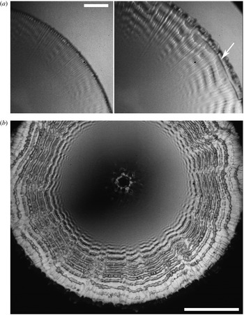
Coexistence of radial and azimuthal lines, for
 $U=2.87~\text{m}~\text{s}^{-1}$
,
 $\unicode[STIX]{x1D6FC}=0.787$
, giving
 $Re_{\unicode[STIX]{x1D6FC}}=16\,700$
and
 $We_{\unicode[STIX]{x1D6FC}}=737$
. (a) Close-up of the shape of the edge. Frames are shown 10 and
 $15~\unicode[STIX]{x03BC}\text{s}$
after first contact. The arrow points at an air cylinder being entrained. The scale bar is
 $100~\unicode[STIX]{x03BC}\text{m}$
long. (b) Rows of numerous vortices shed from around the periphery, revealing up to 15 separate vortices, shown at
 $t=43~\unicode[STIX]{x03BC}\text{s}$
, for the same impact conditions. Scale bar is
 $500~\unicode[STIX]{x03BC}\text{m}$
. Initial velocity of the outer edge
 $\simeq 56~\text{m}~\text{s}^{-1}$
. For reference the drop diameter is
 ${\sim}2$
times the width of this image. See also supplementary movies 3 and 4.

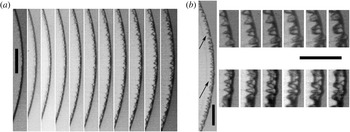
(a) Growth of the teeth for
 $U=2.38~\text{m}~\text{s}^{-1}$
,
 $\text{d}t=0.5~\unicode[STIX]{x03BC}\text{s}$
. (b) Evidence of air sheets on both sides of the ejecta, marked by the arrows. The relative times of these frames are
 $t=0$
, 1.0, 2.20, 2.8, 3.6, 4.0 and
 $4.6~\unicode[STIX]{x03BC}\text{s}$
. Scale bars are
 $100~\unicode[STIX]{x03BC}\text{m}$
long.

For slightly larger
 $Re_{\unicode[STIX]{x1D6FC}}=13\,000$
, in figure 4(b), we see the beginning of axisymmetric vortex shedding (Thoraval et al.
Reference Thoraval, Takehara, Etoh and Thoroddsen2013), with weak intensity undulations in the second frame, followed by short segments of shed vortices in the last frame. For significantly larger
 $Re_{\unicode[STIX]{x1D6FC}}=16\,700$
, in figure 5(a), we see clear coexistence of azimuthal and radial lines. The second panel shows entrainment of a regular air cylinder (arrow). Figure 5(b) shows an identical impact at a smaller optical magnification, where most of the periphery is visible, revealing multiple rows of continuous azimuthal vortices. The axisymmetry is far from perfect, with numerous defects and reconnections. However, the number and spacing of the vortices is essentially identical around the entire periphery.
The number of radial lines increases with the impact velocity. Figure 3(c,d) shows how this total number of lines around the periphery increases with
 $Re_{\unicode[STIX]{x1D6FC}}$
and
 $We_{\unicode[STIX]{x1D6FC}}$
respectively.
Figure 6 shows frame sequences of the formation and breakup of the azimuthal pattern. In (a) we show the growing amplitude of the triangular teeth, which saturates in
 ${\sim}5~\unicode[STIX]{x03BC}\text{s}$
. In (b) we show later evolution of larger air sheets, which overlap and must therefore be pulled in in the sharp corners on both sides of the base of the ejecta sheet (see sketch in figure 1
c).
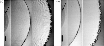
Comparison of edge undulations for identical water drops impacting on (a) a pool of saturated salt solution (
 $t\simeq 0.5,20,34~\unicode[STIX]{x03BC}\text{s}$
) and (b) pure water pool (
 $t\simeq 0.4,15,29~\unicode[STIX]{x03BC}\text{s}$
). Both for
 $U=2.38~\text{m}~\text{s}^{-1}$
,
 $\unicode[STIX]{x1D6FC}=0.828$
, giving
 $Re_{\unicode[STIX]{x1D6FC}}=13\,000$
and
 $We_{\unicode[STIX]{x1D6FC}}=473$
. The arrows point at the outer edge of the central air disc. The scale bars are
 $100~\unicode[STIX]{x03BC}\text{m}$
long.

4 Discussion and conclusions
4.1 Possible effect of density difference between drop and pool
Herein we use different liquids for the drop and pool to enable the visualization. The resulting density difference between the two could affect the dynamics. While this may modify the details, we are convinced this is not the driving force behind the observed phenomena on the following grounds: it is encouraging that the axisymmetric vortex shedding does not change significantly when we reverse the density difference by impacting a water drop on a lighter ethanol pool (
 $\unicode[STIX]{x1D70C}_{p}/\unicode[STIX]{x1D70C}_{d}\simeq 0.79$
in Thoraval et al. (Reference Thoraval, Takehara, Etoh and Thoroddsen2013)) or onto a denser salt-saturated pool (
 $\unicode[STIX]{x1D70C}_{p}/\unicode[STIX]{x1D70C}_{d}\simeq 1.19$
). Furthermore, Thoraval et al. (Reference Thoraval, Takehara, Etoh and Thoroddsen2013) showed that bubble rings are entrained during identical-density water-on-water impacts. Their numerical simulations used the same liquid properties in drop and pool and showed quantitatively consistent results with the experiments, as far as the axisymmetric shedding.
This is also true for the early azimuthal instability studied herein. To verify this we performed a separate set of experiments with a half and a quarter of the salt concentration in the pool, seeing similar results. Finally, some experiments were done with pure water in both drop and pool. Here we can only observe the presence of the azimuthal instability at the interface, as the refractive index difference is now gone. Figure 7 compares the front shapes for the two cases. Panel (b) shows the continued presence of the teeth in the sharp corners, which look the same as with the saturated salt solution in part (a). However, there remains an element of doubt about the presence of the radial lines. Experiments with a truly passive scalar, such as a fluorescent dye, could clarify this, but are not possible with the current optical set-up.
The inviscid Wagner theory of Semenov et al. (Reference Semenov, Wu and Korobkin2015) includes impact of different-density fluids. It deals mostly with much larger density ratios, but shows that the ejecta can bend away from the heavier fluid. This would be of interest to study for liquids with larger density differences.
Marangoni effects, due to difference between
 $\unicode[STIX]{x1D70E}_{drop}$
and
 $\unicode[STIX]{x1D70E}_{pool}$
, should be absent in the sharp corners, as the ejecta separates the two free surfaces, as sketched in figure 1(c). Numerical simulations do indeed show the upper part of the ejecta comes from the drop and its lower part from the pool, see for example Josserand & Zaleski (Reference Josserand and Zaleski2003), Thoraval et al. (Reference Thoraval, Takehara, Etoh, Popinet, Ray, Josserand, Zaleski and Thoroddsen2012, Reference Thoraval, Takehara, Etoh and Thoroddsen2013). Same is true for inviscid theory (Howison et al.
Reference Howison, Ockendon, Oliver, Purvis and Smith2005; Semenov et al.
Reference Semenov, Wu and Korobkin2015). Semenov et al. (Reference Semenov, Wu and Korobkin2015) show that when the drop becomes much denser than the pool, the triple line shifts along the upper side of the ejecta, thus approaching the neck region. However, even at
 $\unicode[STIX]{x1D70C}_{drop}/\unicode[STIX]{x1D70C}_{pool}=20$
it has not reached the neck. It would therefore require a very strong
 $\unicode[STIX]{x0394}\unicode[STIX]{x1D70E}$
driving motions faster than the ejecta velocity, to bring the affected interface region to the neck. Furthermore, only one neck would be affected, while we see instability in both sharp corners at the base of the ejecta. Also, figure 7(b) above shows that the instability shapes persist when the drop and pool are of the same liquid.
Uneven vortex-induced ejecta breakup around the periphery of the neck. (a)
 $t=17~\unicode[STIX]{x03BC}\text{s}$
and (b)
 $t=47~\unicode[STIX]{x03BC}\text{s}$
. Both for
 $U=3.09~\text{m}~\text{s}^{-1}$
,
 $\unicode[STIX]{x1D6FC}=0.79$
,
 $Re_{\unicode[STIX]{x1D6FC}}=17\,900$
and
 $We_{\unicode[STIX]{x1D6FC}}=848$
. The white arrows point out intact sections of ejecta sheet. Black arrows show the sideways contraction of the edge of the ejecta. The scale bar is
 $200~\unicode[STIX]{x03BC}\text{m}$
long. The contrast has been enhanced separately in the four sectors of part (a). See supplementary movie 5.

4.2 Importance and nature of the azimuthal instabilities
What is the significance of these undulations and vortices on the splashing dynamics? Thoraval et al. (Reference Thoraval, Takehara, Etoh, Popinet, Ray, Josserand, Zaleski and Thoroddsen2012) proposed that the onset of random splashing coincides with the axisymmetric shedding of alternating vortices at the base of the ejecta. Figure 8(a) shows a clear demonstration of this importance of the vortex shedding on the breakup of the ejecta, which is here imprinted on a single impact. It shows an anomalous realization where the shedding is non-uniform along the periphery, triggered by localized disturbances in the pool liquid. The ejecta sheet is only visible in the sectors without the vortex shedding, see white arrows. The edges of the intact sections of the sheet contract azimuthally, as indicated by the black arrows. The edge contracts sideways at
 ${\sim}30~\text{m}~\text{s}^{-1}$
, indicating a very thin sub-micron liquid sheet. Figure 8(b) shows how these localized disturbances can trigger chains of vortices, which look like Christmas trees. These grow rapidly in the azimuthal direction and merge. In these realizations, taken early morning, the salt solution may have precipitated some isolated crystals. These forms were not easily reproducible, but persisted for a number of adjacent realizations. Methods of introducing isolated disturbances in a controlled fashion warrant further study. The presence of the radial vortices can clearly influence the primary vortex shedding, especially in the lower range of
 $Re_{\unicode[STIX]{x1D6FC}}$
. See also supplementary movie 6.
Spanwise instabilities of the edges of liquid sheets or thin air films are intrinsic (Reyssat & Quéré Reference Reyssat and Quéré2006; Villermaux Reference Villermaux2007; Craster & Matar Reference Craster and Matar2009; Zhang et al.
Reference Zhang, Brunet, Eggers and Deegan2010; Agbaglah et al.
Reference Agbaglah, Josserand and Zaleski2013). Regular triangular teeth have also been observed before (Thoroddsen et al.
Reference Thoroddsen, Takehara and Etoh2012a
,Reference Thoroddsen, Thoraval, Takehara and Etoh
b
; Gordillo et al.
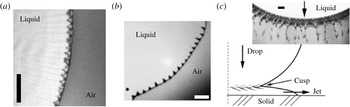
Reference Gordillo, Lhuissier and Villermaux2014). These instabilities are most frequently driven by capillarity, while we believe viscosity plays a role in the triangular form. Figure 9 shows three separate sharp air-corner configurations, all of which develop azimuthal patterns. Panel (a) shows the present drop on pool impact, while (b) is from the rupture of a thin air film. Finally, part (c) shows fine azimuthal structures observed during a drop impact on a solid surface. We therefore conclude that the focus should not be on capillary instabilities at the tip of the ejecta (Weiss & Yarin Reference Weiss and Yarin1999), but rather in the sharp corners which develop on its two sides (see figure 1
c). On the other hand, perhaps Rayleigh instability of the tip helps destabilize the corners. We can see whether this is plausible by inferring the ejecta thickness
 $\unicode[STIX]{x1D6FF}$
from the initial azimuthal wavelength of the triangular pattern, using
 $\langle N\rangle$
and
 $R_{s}$
from figure 3(b). Based on this,
 $\unicode[STIX]{x1D6FF}\simeq 0.2218\times 2\unicode[STIX]{x03C0}R_{s}/\langle N\rangle$
, which for our impacts reduces from 34 to
 $8~\unicode[STIX]{x03BC}\text{m}$
as
 $We_{\unicode[STIX]{x1D6FC}}$
increases over our range. These thicknesses are quantitatively similar to those measured in Thoroddsen (Reference Thoroddsen2002), but the ejecta thickness cannot be measured in the current experiments.
Vorticity is produced by flow along a curved free surface, see § 5.14 in Batchelor (Reference Batchelor1967). Once these azimuthal undulations have formed, the flow past the triangular three-dimensional free surfaces will produce both radial and azimuthal components of vorticity (Peck & Sigurdson Reference Peck and Sigurdson1998), the former of which will promote the formation of the observed radial lines. We propose by the symmetry that the surfaces leading to the tip of each triangular shape will promote opposite-sign vortices trailing radially into the neck liquid.
Triangular edge shapes for retracting air sheets in three different configurations. (a) Close up of the front for the conditions in figure 4(b). (b) The edge of a rupture in a thin air layer during Mesler entrapment, taken from figure 4(c) in Thoroddsen et al. (Reference Thoroddsen, Thoraval, Takehara and Etoh2012b
). (c) Undulations in the sharp corner between drop and lamella, when a drop impacts on a solid surface. Modified from figure 1 in Thoroddsen et al. (Reference Thoroddsen, Takehara and Etoh2012a
). The scale bars are
 $100~\unicode[STIX]{x03BC}\text{m}$
long.

The very similar triangular shapes appearing for the pressure-driven impact ejecta and for the rupture of an air film from rest, may be coincidental, or suggest that the rapid deceleration of the ejecta base is not important. The liquid flow fields around the edge are qualitatively different in these two cases. For the rupture edge, one can expect the capillary number
 $\unicode[STIX]{x1D707}U/\unicode[STIX]{x1D70E}$
, to be important for the balance of
 $\unicode[STIX]{x1D70E}$
and
 $\unicode[STIX]{x1D708}$
. For the two impact cases (figure 9
a,c) the flow wraps around the edge without a stagnation point. The asymptotic stability of such flow was recently studied by Moore et al. (Reference Moore, Ockendon, Ockendon and Oliver2014), including
 $\unicode[STIX]{x1D70E}$
and
 $\unicode[STIX]{x1D708}$
. While a capillary instability wavelength above is consistent with the thickness of the emerging ejecta sheet, which is bounded by two sharp corners, the drop-on-solid impact only has one sharp corner, with a bound lamella.
We suggest the inviscid axisymmetric base flow, around one of the sharp corners at the base of the ejecta, moving for example from the drop and entering into the ejecta sheet, will be unstable to azimuthal undulations. An azimuthal undulation will introduce a change in the radial distance from the axis of symmetry, which will change the local sharpness of the corner based on its axial base geometry. Smaller neck radius will produce a locally sharper corner, which in turn leads to larger velocity and enhanced Bernoulli suction pressure, needed to turn the flow through a larger angle. This pulls the free surface in the corner further towards the axis, making it still sharper which is turn reduces the pressure even more, producing a reinforcing feedback. Surface tension will also become stronger as the corner curvature increases, thereby stopping the growth in amplitude and helping form the secondary three-dimensional flow around the triangular shapes.
We should also mention the possibility of a Rayleigh–Taylor instability of a decelerated density interface, where the fastest growing instability mode is
 $k_{max}=\sqrt{\unicode[STIX]{x1D70C}\,a/(3\unicode[STIX]{x1D70E})}$
, where
 $a$
is the deceleration. The neck radius is rapidly decelerating, as can be calculated by twice differentiating equation (3.1). This does predict wavelengths of the right order of magnitude. As an example, the front in the first image of figure 4(a) is decelerating at
 ${\sim}10^{6}~\text{m}~\text{s}^{-2}$
, giving a wavelength of maximum growth of
 $\unicode[STIX]{x1D706}_{max}=2\unicode[STIX]{x03C0}/k_{max}\simeq 68~\unicode[STIX]{x03BC}\text{m}$
. For comparison the measured wavelength in the image is
 $\unicode[STIX]{x1D706}\simeq 14~\unicode[STIX]{x03BC}\text{m}$
. One problem with this argument is when to calculate the deceleration, as the instability does not appear immediately following first contact, when the deceleration is largest. Of more concern is the true role of surface tension in our configuration. The largest surface curvature is not, in the axial, in the direction of the instability, so how azimuthal undulations would affect the capillary pressure is not clear.
4.3 Summary
Herein, we have investigated the earliest dynamics following the contact between a drop impacting a liquid surface. Our focus is on the outer contact where the ejecta sheet emerges. We have shown that for
 $Re_{\unicode[STIX]{x1D6FC}}>7000$
the neck region develops fine azimuthal undulations, thereby loosing axisymmetry. Similar undulations were first reported by Thoraval et al. (Reference Thoraval, Takehara, Etoh and Thoroddsen2013), but here we reveal the onset and details of their structure. Using salt solutions in a pool, we are able to observe clear radial striations emanating from these tooth-like patterns in the neck region. These undulations are consistent with capillary instability in the neck. The undulations can occur on both sides of the ejecta and promote the formation of minute triangular air sheets.
The azimuthal instability occurs earlier and independently of the axisymmetric vortex shedding discovered by Thoraval et al. (Reference Thoraval, Takehara, Etoh, Popinet, Ray, Josserand, Zaleski and Thoroddsen2012). This is clear from the appearance of the radial streaks in figure 4(a) at very small neck radii, before any axisymmetric shedding is observed. The presence of this earlier instability explains why the azimuthal vortices are never perfectly axisymmetric around the entire periphery.
Many possible extensions arise from this work. Fully three-dimensional numerical simulations will be needed to capture the vortex structure in the neck region, as well as to see the interactions between the two sides of the base of the ejecta. To pin down the relative importance of viscosity and surface tension in this instability, experiments must be conducted with a range of different liquids and for larger impact velocities.
Acknowledgements
The work reported herein was funded by King Abdullah University of Science and Technology (KAUST) under grant URF/1/2621-01-01. E.Q.L. acknowledges the Thousand Young Talents Program of China, the National Natural Science Foundation of China (grants nos 11772327, 11642019 and 11621202) and Fundamental Research Funds for the Central Universities (grant no. WK2090050041). M.-J.T. acknowledges the financial support from the National Natural Science Foundation of China (grant nos 11542016 and 11702210) and the 111 project (B18040). M.-J.T. is also supported by the Cyrus Tang Foundation through the Tang Scholar program, and by the Thousand Young Talents Program of China. We thank W. Chan and K. Taylor at Specialized Imaging for their assistance.
Supplementary movies
Supplementary movies are available at https://doi.org/10.1017/jfm.2018.383.