Introduction
High-entropy alloys (HEAs), composed of multiple principal elements, tend to form a single-phase solid solution because of their high configurational entropy.Reference Yeh, Chen, Lin, Gan, Chin, Shun, Tsau and Chang1,Reference Otto, Yang, Bei and George2 This new class of materials shows interesting properties, such as promising strength and ductility,Reference Stepanov, Shaysultanov, Salishchev and Tikhonovsky3–Reference Fujieda, Shiratori, Kuwabara, Hirota, Kato, Yamanaka, Koizumi, Chiba and Watanabe5 and good corrosion,Reference Xiao, Zhou, Wu, Diao, Gao, Song and Liaw6,Reference Qiu, Thomas, Gibson, Fraser and Birbilis7 irradiation,Reference Granberg, Nordlund, Ullah, Jin, Lu, Bei, Wang, Djurabekova, Weber and Zhang8 and wear resistance.Reference Chuang, Tsai, Wang, Lin and Yeh9 In particular, high-temperature properties of HEAs, such as high-temperature strengthReference Senkov, Wilks, Miracle, Chuang and Liaw10,Reference Wu, Bei, Otto, Pharr and George11 and good thermal and microstructure stability,Reference Yao, Pradeep, Tasan and Raabe12,Reference Schuh, Mendez-Martin, Völker, George, Clemens, Pippan and Hohenwarter13 are important and necessary for elevated-temperature engineering applications,Reference Miracle, Miller, Senkov, Woodward, Uchic and Tiley14 such as in gas turbines in the aerospace industry.Reference Senkov, Wilks, Miracle, Chuang and Liaw10,Reference Miracle, Miller, Senkov, Woodward, Uchic and Tiley14,Reference Praveen and Kim15
Nanoscale time-dependent mechanical testing of alloy materials is usually conducted via microelectromechanical systems (MEMS)Reference Modlinski, Witvrouw, Ratchev, Puers, den Toonder and De Wolf16 or nanoindentation systems.Reference Chavoshi and Xu17 For the latter, with the high accuracy of depth-sensing technology and stable temperature-controlling stages in current instruments, the time-dependent mechanical behavior of HEAs can be conducted on localized regions, ignoring the limit of standard-sized specimens, especially in traditional creep testing. Several studies have reported the time-dependent mechanical properties of HEAs via nanoindentation, including the elevated-temperature creep of FeCoNiCrMn and FeCoNiCrMn-Al HEAs at 300–600°C,Reference Tsai, Huang, Lin, Liu, Liao, Jang, Song and Nieh18 room-temperature creep of as-deposited and annealed CoCrFeCuNi HEA thin films,Reference Ma, Peng, Wen and Zhang19 room-temperature creep of as-cast and severelyplastic-deformed CoCrFeMnNi,Reference Lee, Seok, Zhao, Choi, He, Lu, Suh, Ramamurty, Kawasaki, Langdon and Jang20 initial creep behavior of CoCrNi HEA,Reference Wang, Guo, Wang, Liu, Wang, Yang and Liu21 characteristics of plastic deformation in CoCrFeMnNi HEA from room temperature to 300°C,Reference Lee, Choi, Yang, Lu, Kawasaki, Ramamurty, Schwaiger and Jang22 strain rate sensitivity of AlCoCrFeNi HEA at room temperature,Reference Jiao, Wang, Wu and Qiao23 room-temperature creep in CoCrFeNiCu HEA with a face-centered-cubic (fcc) structure,Reference Ma, Feng, Debela, Peng and Zhang24 and room-temperature creep in CoCrFeNiCuAl2.5 HEA with a body-centered-cubic (bcc) structure.Reference Ma, Feng, Debela, Peng and Zhang24
In this article, we focus on creep properties, explored using nanoindentation, on several well-known HEAs, such as FeCoNiCrMn (also known as the Cantor alloy) and extended alloy systems. Several important parameters that play an important role in creep behavior are discussed, such as minor solute addition effects in HEAs, structure effects, grain-size effects, and orientation effects. This article summarizes the current findings in HEAs based on nanoindentation creep. It is hoped that more exploration using this new method of nanoindentation can provide new scientific findings on the high-temperature properties of HEAs.
Creep behavior of HEAs at elevated temperatures
Minor solute addition effects—Al in FeCoNiCrMn HEA
Tsai et al.Reference Tsai, Huang, Lin, Liu, Liao, Jang, Song and Nieh18 reported the impact of Al addition in a HEA matrix. Elevated-temperature creep measurements on Fe20Co20Ni20Cr20Mn20 (FeCoNiCrMn) and Fe18Co18Ni20Cr18Mn18Al8 (FeCoNiCrMn-Al) HEAs using nanoindentation in the temperature range of 300–600°C were conducted. FeCoNiCoMn and FeCoNiCoMn-Al exhibit fcc structure and fcc + bcc structure, respectively. Figure 1a–b present the relationship between creep displacement (h) and creep holding time (t) of FeCoNiCrMn and FeCoNiCrMn-Al HEAs, respectively. The strain rate ( ${\rm{\dot{\varepsilon }}}$) as a function of creep time period, t, can be obtained based on
 ${\rm{\dot{\varepsilon }}} = {1 \over h}{{dh} \over {dt}}$, as shown in Figure 1c–d.
Representative creep displacement–creep holding time (h–t) curves for (a) FeCoNiCrMn {111} grains and (b) face-centered-cubic (fcc) {111} grains in dual-phase FeCoNiCrMn-Al. Representative creep strain rate–creep time period ( ${\rm{\dot{\varepsilon }}}-$t) curve for (c) FeCoNiCrMn {111} grains and (d) fcc {111} grains in dual-phase FeCoNiCrMn-Al.Reference Tsai, Huang, Lin, Liu, Liao, Jang, Song and Nieh18

The work of Li et al. illustrates how the creep stress exponent (n) is equal to the inverse of the strain-rate sensitivity (m).Reference Li, Henshall, Hooper and Easterling25 For FeCoNiCrMn, the average stress exponent n values of the fcc {111} planes are 3.8 (m ∼ 0.263) in the temperature range of 400–600°C.Reference Tsai, Huang, Lin, Liu, Liao, Jang, Song and Nieh18 With decreasing temperature, n shows a dramatic jump to 14 at room temperature. Similarly, for the fcc {111} grains in FeCoNiCrMn-Al, the average n value over 400–600°C is approximately 4.3 (m ∼ 0.233) and increases to approximately 5.0 at 300°C and about 14 at room temperature.Reference Tsai, Huang, Lin, Liu, Liao, Jang, Song and Nieh18 The creep strength of the Al-modified Cantor alloy, FeCoNiCrMn-Al, is comparable to that in the standard Cantor alloy, suggesting that the solid-solution effect (only ∼4 at.% Al remaining in the fcc grains and remaining Al present in the bcc grains) is insignificant for the fcc {111} grains at elevated temperatures.Reference Tsai, Huang, Lin, Liu, Liao, Jang, Song and Nieh18 In the temperature range of 400–600°C, the stress exponent n is approximately 4 ± 1 (or m ∼ 0.25) for both of FeCoNiCrMn and FeCoNiCrMn-Al, suggesting possible climb-controlled dislocation creep.Reference Tsai, Huang, Lin, Liu, Liao, Jang, Song and Nieh18 Creep is a thermally activated process, and the creep activation energy, Q c, is linked to the activation energy for vacancy diffusion. The creep activation volume V c for the fcc {111} grains in these two HEAs reaches approximately 140 Å3 at 600°C, which is larger than the typical activation volume of 50–100 Å3 for Ni-based alloys.Reference Li, Henshall, Hooper and Easterling25–Reference Knezevic, Schneider and Landier29
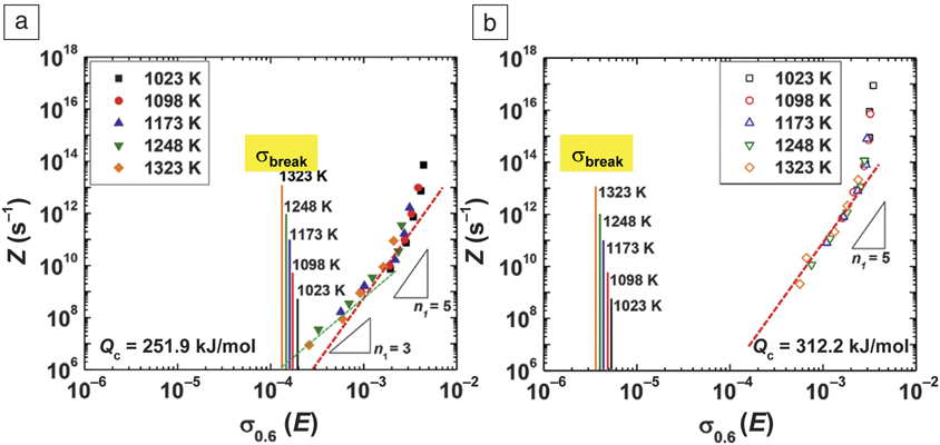
In traditional dilute alloys, dislocation climb is controlled by vacancy diffusion, which involves a simple one-to-one atom–vacancy exchange. In HEAs, however, the lattice is distorted because of the different sizes as well as the chemistry of the constituent atoms. A vacancy is surrounded by various constituent elements, and vacancy–element exchange during diffusion is more complicated, involving the cooperative motion of several atoms in order to maintain compositional portioning.Reference Tsai, Huang, Lin, Liu, Liao, Jang, Song and Nieh18 This collective atomic motion would certainly expand the activation volume to that larger than a single atom. Kim et al.Reference Kim, Jeong, Park, Park, Na and Choi30 reported that a solute drag effect occurs at low strain rates and at high temperatures, and the rate-controlling deformation mechanism is in relation to Al atoms. The estimated values of σbreak,Reference Friedel31 which represents the critical stresses for the breakaway of dislocations from the Al solute environment, are 25.5 and 14.5 MPa at 1023 and 1323 K, respectively.Reference Kim, Jeong, Park, Park, Na and Choi30 For equiatomic CoCrFeMnNi, Cr holds the largest size factor e i (=(r i-r average)/r average, where r i and r average represent the particular atom radius and the average radius), equal to 1.46 × 10⁻², among the five constituents.Reference Kim, Jeong, Park, Park, Na and Choi30 Thus, Cr is most likely to form the solute atmosphere around the dislocations. The σbreak of the Cr element is about 32× smaller than those of Al0.5CoCrFeMnNi. Figure 2a–b
Log Z-log (σ0.6/E) plots at ε = 0.6 for (a) Al0.5CoCrFeMnNi and (b) CoCrFeMnNi.Reference Kim, Jeong, Park, Park, Na and Choi30,Reference Jeong, Park, Park, Na and Kim32 Solute drag creep is dominant at very low strain rates in CoCrFeMnNi, but hardly contributes to hot deformation at the typical strain rate range for hot metal working, unlike Al0.5CoCrFeMnNi. Note: σbreak, breakaway stress; Q c, activation energy; Z, Zener–Hollomon parameter; σ0.6, stress at a strain of 0.6; E, Young’s modulus; n, creep stress exponent.

Reference Kim, Jeong, Park, Park, Na and Choi30,Reference Jeong, Park, Park, Na and Kim32 show the solute drag creep becoming dominant at very low strain rates in CoCrFeMnNi, and hardly contributing to hot deformation in the typical strain rate range for hot metal working, unlike Al0.5CoCrFeMnNi.Reference Kim, Jeong, Park, Park, Na and Choi30
Structure effects
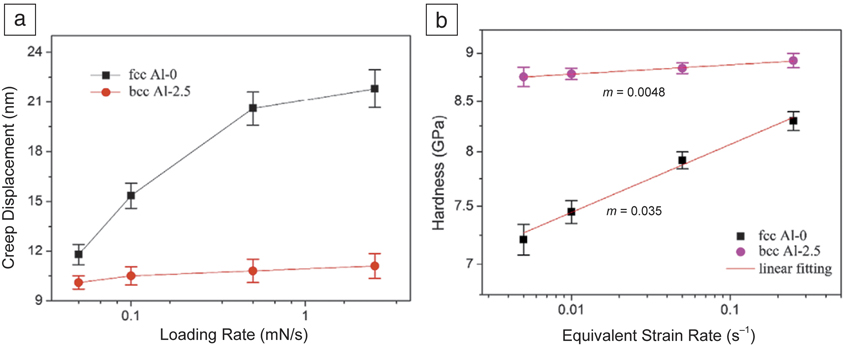
Ma et al.Reference Ma, Feng, Debela, Peng and Zhang24 studied the strain-rate sensitivity, m, and activation volume, V c, of a CoCrFeNiCu (zero Al, namely, Al-0) HEA thin film with a fcc structure and CoCrFeNiCuAl2.5 (2.5 at.% Al, namely, Al-2.5) HEA thin film with a bcc structure at room temperature. Figure 3a shows the creep displacement as a function of loading rate (log scale) from 0.05 mN/s to 2.5 mN/s. In the Al-0 film, the creep displacement almost doubled from 11.8 nm to 21.8 nm with increasing loading rate.Reference Ma, Feng, Debela, Peng and Zhang24 However, the Al-2.5 film maintained a stable creep displacement from 0.05 mN/s to 2.5 mN/s.Reference Ma, Feng, Debela, Peng and Zhang24 It can be concluded that the creep of Al-0 film had a strong correlation with the loading rate. The higher the loading rate, the greater disparity of creep displacements between Al-0 and Al-2.5.
(a) Creep displacement as a function of the loading rate (log scale) for Al-0 and Al-2.5 high-entropy alloy ([HEA] CoCrFeNiCu) films. The creep for the Al-0 film strongly correlates with the loading rate. The higher the loading rate, the greater disparity of creep displacements between Al-0 and Al-2.5 (b) Nanoindentation hardness versus equivalent strain rates (log scale) of the HEA films for calculation of strain-rate sensitivities. These values are typical for face-centered-cubic (fcc) and body-centered-cubic (bcc) nanocrystalline metals and in agreement with previous experimental studies. Note: m, strain-rate sensitivity.Reference Ma, Feng, Debela, Peng and Zhang24

Figure 3b shows the relationship between hardness and equivalent strain rate (log scale) for the Al-0 and Al-2.5 films. The value of m can be deduced from the slope of the linear regression lines, yielding m = 0.035 for the fcc Al-0 and m = 0.0048 for the bcc Al-2.5.Reference Ma, Feng, Debela, Peng and Zhang24 These results for the two HEAs are typical for fcc and bcc nanocrystalline metals according to previous experimental studies. A high value of m is obtained in ductile metals, in which plastic deformation is relatively more nonlocalized (preventing necking or shear banding in crystalline or amorphous alloys).Reference Bhattacharyya, Singh, Eswar Prasad, Narasimhan and Ramamurty33 The activation volume for dislocation nucleation in HEA films can be estimated based on the strain-rate sensitivity and shear stress.Reference Woo, Huang, Ngan and Yu34 The activation volume obtained is 0.08 nm3 for Al-0 and 0.51 nm3 for Al-2.5.Reference Ma, Feng, Debela, Peng and Zhang24 The significant enlargement of the activation volume thus predicts a reduction in strain-rate sensitivity with the structure transition from fcc to bcc. However, the underlying mechanism for the distinction of the activation volumes between nanocrystalline fcc and bcc HEAs remains unknown and was outside of the scope of that study.Reference Ma, Feng, Debela, Peng and Zhang24
In addition to well-known factors such as the film structure, alloy system, and grain size, creep response also appears to be strongly dependent on the thermal history of sample preparation. For example, with the fast cooling rate in sputtering, the inner structure of the as-deposited HEA films remains in the nonequilibrium state with higher residual stress.Reference Ma, Peng, Wen and Zhang19 With the aid of annealing, flaws, lattice distortion, and residual stress would be reduced, yielding a stable structure for creep behavior.Reference Ma, Peng, Wen and Zhang19
Grain-size effects
Recently, nanocrystalline HEAs have been widely investigated for their high-strength and high-temperature mechanical behavior. Zou et al. reported that the Nb25Ta25Mo25W25 refractory HEA exhibits an extraordinarily high yield strength of greater than 5 GPa at temperatures of up to 600°C, using micro-compression tests; this is 5× higher than that of its single-crystal equivalent.Reference Zou, Wheeler, Ma, Okle and Spolenak35
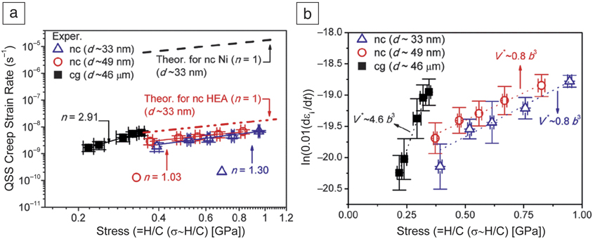
Lee et al. also reported another significant result for nanocrystalline FeCoNiCrMn HEA creep behavior where nanoindentation analysis was performed with a constant loading rate of 0.5 mN/s and held for 1000 s at different maximum loads.Reference Lee, Seok, Zhao, Choi, He, Lu, Suh, Ramamurty, Kawasaki, Langdon and Jang20 With high-pressure torsion (HPT) processing, the grain size was reduced from ∼46 μm (coarse grains [cgs]) for the as-cast state to ∼33 nm (nanocrystalline [nc]) after HPT processing. It was found that the creep stress exponent, n, extracted from the nanoindentation creep test was ∼3 for coarse grains, while n was ∼1 for nanocrystalline material, as shown in Figure 4a.Reference Lee, Seok, Zhao, Choi, He, Lu, Suh, Ramamurty, Kawasaki, Langdon and Jang20
(a) Relationship between quasi-steady-state (QSS) creep strain rate and stress; the slope corresponds to the creep stress exponent, n. n is extracted from the nanoindentation creep test and was ∼3 for coarse grains (cgs) and was ∼1 for nanocrystalline (nc) material. (b) Logarithmic strain rate versus linear stress relation to estimate the activation volume (V*) for creep. The results indicate a transition from the dislocation-controlled mechanism in the coarse-grain state to the diffusion-controlled mechanism in the nanocrystalline state.Reference Lee, Seok, Zhao, Choi, He, Lu, Suh, Ramamurty, Kawasaki, Langdon and Jang20 Note: d, grain size; H, hardness; C, constant factor, typically ∼3 for metals; εi, indentation strain rate; b, Burgers vector; HEA, high-entropy alloy.

The activation volumes were also extracted, presenting a value of 4.6 b Reference Stepanov, Shaysultanov, Salishchev and Tikhonovsky3 (b is Burgers vector) for the coarse-grained structure, while the value was 0.8 b Reference Stepanov, Shaysultanov, Salishchev and Tikhonovsky3 for the nanocrystalline structure (Figure 4b).Reference Lee, Seok, Zhao, Choi, He, Lu, Suh, Ramamurty, Kawasaki, Langdon and Jang20 The results indicate the transition from the dislocation-controlled mechanism in the coarse-grain state to the diffusion-controlled mechanism in the nanocrystalline state. Elevated temperature creep tests from room temperature to 300°C using the nanoindentation system were carried out by the same group using strain-rate jump tests with three different strain rates (0.025, 0.008, and 0.0025 s–1),Reference Lee, Choi, Yang, Lu, Kawasaki, Ramamurty, Schwaiger and Jang22 presenting the activation enthalpy for different temperatures. With temperatures lower than 473 K, the activation enthalpy was about 0.5 eV, indicating that the deformation is controlled by grain-boundary-mediated dislocation activity.Reference Lee, Seok, Zhao, Choi, He, Lu, Suh, Ramamurty, Kawasaki, Langdon and Jang20 A significant increase in activation enthalpy to about 1.8 eV for temperatures higher than 473 K was observed.Reference Lee, Seok, Zhao, Choi, He, Lu, Suh, Ramamurty, Kawasaki, Langdon and Jang20 This was attributed to the enhancement of grain-boundary diffusion.
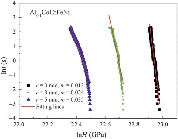
Yu et al.Reference Yu, Cheng, Zhang, Zhang, Jing, Ma, Liaw, Li and Liu36 reported a similar trend in the Al0.1CoCrFeNi alloy at room temperature with a 400 μN/s loading rate, up to 4000 μN maximum load and holding for 10 s. With decreasing grain size, the strain-rate sensitivity increased, leading to a decrease in activation volume (Figure 5).Reference Yu, Cheng, Zhang, Zhang, Jing, Ma, Liaw, Li and Liu36 It should be noted that the sample was processed by HPT as well, leading to coarser grains in the middle and finer grains at the edge (r represents the distance from the center). The results indicate that the dominant mechanism of creep changes from dislocation slip to grain-boundary sliding, resulting in lower creep resistance with decreasing grain size.Reference Yu, Cheng, Zhang, Zhang, Jing, Ma, Liaw, Li and Liu36 However, nanocrystalline alloys have never been used at elevated temperatures because of their poor high-temperature strength and stability. Therefore, the development of thermally stable nanocrystalline systems that can retain high strengths over a wide temperature range are highly desirable for both scientific study and engineering applications.
Dependence of ln t versus lnH for the Al0.1CoCrFeNi alloy after high-pressure torsion at 6 GPa for N = 2, at different positions from the sample center (r). Coarser grains were located in the middle of the sample and finer grains were located at the edge of the sample. With decreasing grain size (increasing r), the strain-rate sensitivity increased, leading to a decrease in activation volume. The dominant creep mechanism changes from dislocation slip to grain-boundary sliding, resulting in lower creep resistance.Reference Yu, Cheng, Zhang, Zhang, Jing, Ma, Liaw, Li and Liu36 Note: H, hardness; t, time ; N, number of torsion for 360°; m, strain-rate sensitivity.

Orientation effects
The anisotropic behavior in elevated-temperature creep deformation is another important mechanical characteristic. To exploit this for potential applications, it is necessary to develop a predictive system that can model effects of crystallographic anisotropy on high-temperature creep deformation of such materials. GhoshReference Ghosh37 reported the simulation of anisotropic behavior and creep resistance of single-crystal Ni-based superalloys. Wen et al.Reference Wen, Zhang, Li, Yue and Gao38 also reported high-temperature creep testing on notched samples.
To enhance the efficiency of creep testing, elevated-temperature creep via nanoindentation provides an efficient and precise method for research. The nanoindentation probe interacts with the samples at localized regions of the grains, which are much larger than the area indented by the indentation tip. This can be essentially treated as creep testing of a single crystal, which means the influence of the grain boundary can be neglected. Because of this, the single-crystal creep behavior can be extracted from a polycrystalline sample, reducing the difficulty of sample preparation.
Tsai et al.Reference Tsai, Huang, Lin, Liu, Liao, Jang, Song and Nieh18 reported the elevated-temperature creep of fcc {100} and {111} FeCoNiCrMn HEAs. The elastic modulus of FeCoNiCrMn dropped from 190 ± 7 for {111} to 166 ± 5 for {100}; the corresponding hardness decreased from 2.9 ± 0.2 to 2.4 ± 0.2 GPa, respectively, when compared to the room-temperature elastic modulus and hardness of {111} and {100} grains. This result is similar to that observed for pure Ni,Reference Hu, Zheng, Hu, He and Yue39 Ni-based superalloys,Reference Wen, Zhang, Li, Yue and Gao38 and a fcc FeCoNiCrReference Wu, Gao and Bei40 and FeCoNiCrMnReference Kireeva, Chumlyakov, Pobedennaya, Kuksgausen and Karaman41 HEA single crystal, in which the strength along the 〈111〉 orientation is stronger than that along 〈100〉.
For elevated temperature creep behavior, fcc {111} grains are stronger than fcc {100} grains. At 550°C, the creep displacement was 75 nm for the {100} grains, but only 60 nm for the {111} grains. The activation volumes for {100} at elevated temperatures are also higher than those for {111}, suggesting that the creep resistance of the fcc {111} grains is higher than that of the fcc {100} grains.Reference Tsai, Huang, Lin, Liu, Liao, Jang, Song and Nieh18 Despite this difference between {111} and {100} grains, the creep mechanism of these fcc {111} and {100} grains was shown to be the same, as deduced from the similar stress exponent and activation energy (Figure 6).Reference Tsai, Huang, Lin, Liu, Liao, Jang, Song and Nieh18 Few reports have focused on orientation effects, besides this work, and further exploration is clearly needed. These results showcase one of the benefits of using nanoindentation for creep characterization in polycrystalline materials. The individual creep response from each crystalline orientation would not be possible with traditional creep testing on bulk samples.
The dependence of ln(strain rate) versus 1/T for (a) {111} grains and (b) {100} grains in Fe20Co20Ni20Cr20Mn20. The creep mechanism of these face-centered-cubic (fcc) {111} and {100} grains are the same, as deduced from the similar stress exponent and activation energy values.Reference Tsai, Huang, Lin, Liu, Liao, Jang, Song and Nieh18 Note: Q c, activation energy;  ${\rm{\dot{\varepsilon }}}$, strain rate; T, temperature.

Comparison and discussion
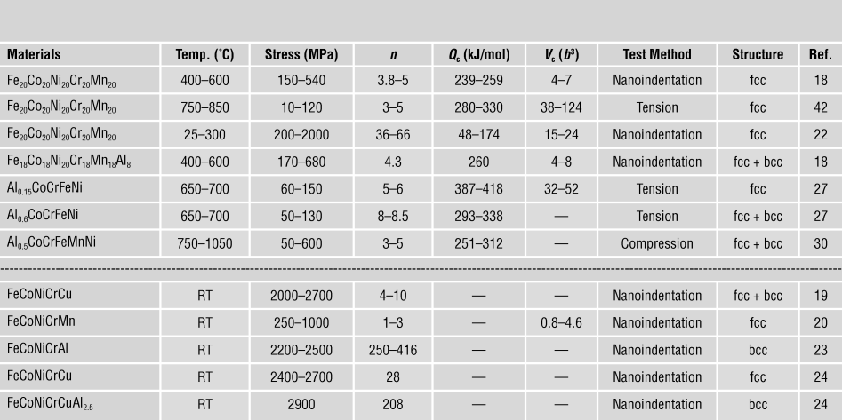
Creep data for various HEAs measured by different creep testing methods are compared in Table I,Reference Tsai, Huang, Lin, Liu, Liao, Jang, Song and Nieh18–Reference Lee, Seok, Zhao, Choi, He, Lu, Suh, Ramamurty, Kawasaki, Langdon and Jang20,Reference Lee, Choi, Yang, Lu, Kawasaki, Ramamurty, Schwaiger and Jang22–Reference Ma, Feng, Debela, Peng and Zhang24,Reference Cao, Shang, Zhao, Cheng, Wang and Wang27,Reference Kim, Jeong, Park, Park, Na and Choi30,Reference He, Zhu, Zhou, Liu, Nieh and Lu42 and divided into elevated-temperature and room-temperature data. Note that some data were converted or extracted from published figures, since they were not presented in the original papers. The grain-size effects and the strain-rate effects on creep response are normally studied at room temperature to avoid the influence of thermal drift. Also, some nanocrystalline samples are not stable at elevated temperatures.
Comparison of the extracted creep stress exponent (n), activation energy (Q c), and activation volume (V c) from different reported creep tests.

Note: b, Burgers vector; RT, room temperature.
Generally, the creep mechanism at elevated temperatures is controlled by several critical parameters such as strain rate, stress, grain size, and creep temperature. When comparing the results of elevated temperature nanoindentation creep response with traditional creep tension tests for the FeCoNiCrMn alloy subjected to a normal lower stress level in the range of 10–150 MPa, the stress exponents (approximately 3–8), activation energies (around 300–400 kJ/mol), and activation volumes (around 40–100 b 3) are similar, suggesting that the mechanisms should be the same, likely due to dislocation climb-controlled creep. For such a lower stress level (and thus a lower strain rate level), lattice diffusion could play a dominant role. A higher activation volume has been found in many HEAs since these would induce collective atom motion during the creep deformation.
In comparison, in order to prevent strong thermal drift, nanoindentation creep testing at elevated temperatures from 400–600°C usually adopts a much shorter creep testing duration by raising the creep stress level to around 200 to 500 MPa, or even higher. Note from Table I that the extracted stress exponents (approximately 3–5) and activation energies (around 240–260 kJ/mol) are still comparable to those reported from traditional creep tension tests, implying a similar creep deformation mechanism. The slightly lower activation energy could be a result of grain-boundary and dislocation pipe diffusion that have been involved in the nanoindentation creep testing adopting much higher creep stress levels. The extracted activation volume (around 4–8 b 3) also appears to be much lower than those extracted by the by traditional creep tension tests (40–100 b 3). This is likely the result of much higher stress and strain rate levels, such that fewer atoms are involved in the collective motion. Additionally, the nanoindentation probe region interacting with the sample is considerably smaller, causing a relatively higher loading pressure and lower activation volume. Nevertheless, this might also be an advantage for using nanoindentation creep testing, which can be conducted on a specific small region to investigate the creep behavior of a particular regime or particular second phases.
Summary and future directions
Current findings on nanoscale time-dependent creep behavior of HEAs, explored using the nanoindentation technique, are reviewed. With the advantage of depth-sensing technology and a precise temperature control system, identification of elevated-temperature mechanical behavior, such as room-temperature and elevated-temperature creep responses, is now possible. HEA creep response related to minor solute addition effects, structure effects, grain-size effects, and orientation effects are reviewed and discussed. These findings are useful for future alloy design of advanced high-entropy materials. In particular, anisotropic mechanical properties at room and elevated temperatures for various grain orientations in individual fcc or bcc grains of HEAs can be revealed by the nanoindentation technique. Traditional creep testing on bulk samples will not show individual creep response from each crystalline orientation. In addition, the region where the nanoindentation probe interacts with the sample is quite small, which could be an advantage in using nanoindentation creep testing. Such testing can be conducted on a specific small-sized region to investigate the creep behavior of a particular regime or second phase.
Acknowledgments
The authors gratefully acknowledge support from the Ministry of Science and Technology of Taiwan, ROC, under Grant No. MOST-105–2221-E-110–019-MY31, and from the City University of Hong Kong under Grant Nos. 9380088, 7005078, and 9231348. T.G.N. was supported by the National Science Foundation under Contract No. DMR-1408722.

P.H. Lin is a doctoral candidate in the Department of Materials and Optoelectronic Science at National Sun Yat-sen University, Taiwan. He received his bachelor’s degree from National Sun Yat-sen University in 2015. His current research focuses on elevated-temperature mechanical characteristics of high-entropy alloys. Lin can be reached by email at linnantou12345@gmail.com.

H.S. Chou is a postdoctoral research fellow at National Sun Yat-sen University, Taiwan. He received his PhD degree from National Sun Yat-sen University in 2011. He was a R&D supervisor at Sino-American Silicon Products Inc. from 2011 to 2018. His research focuses on mechanical characteristics of high-entropy alloys, thin-film metallic glasses, and directional solidification in silicon crystals. Chou can be reached by email at sapphirerei@gmail.com.

J.C. Huang has been a senior vice president at National Sun Yat-sen University, Taiwan, and the National Chair Professor, Taiwan, since 2006. He also serves as the Chair Professor of Materials Science and Engineering and Executive Director of the Institute for Advanced Study at the City University of Hong Kong. He received his BS degree from National Tsing Hua University, Taiwan, in 1979, and MS and PhD degrees from the University of California, Los Angeles, in 1983 and 1986. He was a research fellow at Los Alamos National Laboratory from 1987 to 1989. Huang’s research includes thin-film metallic glasses, multilayer and interface studies, low-density high-entropy alloys, 3D printing/additive manufacturing, biocompatible implants using gradient porous Ti foams, and nanocrystalline materials. He has published more than 325 journal papers, as well as conference papers and patents. Huang can be reached by email at chihuang@cityu.edu.hk.

W.S. Chuang has been a postdoctoral research fellow at National Sun Yat-sen University, Taiwan, since 2018. He received his PhD degree from National Sun Yat-sen University in 2018. His research focuses on structural characteristics of different materials, especially through transmission electron microscopy, nanomechanical characteristics of Mg-Zn-Y alloys and other materials, and deformation mechanism analysis. Chuang can be reached by email at egg037105218@yahoo.com.tw.

J.S.C. Jang is a distinguished professor at the Institute of Materials Science and Engineering, and the director of the Precision Instrument Utilization Center at National Central University, Taiwan. He received his PhD degree in materials science from North Carolina State University in 1989. His research focuses on the alloy design of high-performance alloys, such as bulk metallic glass (BMG) and composites (BMGC), intermetallics, and lightweight high-entropy alloys. BMG, BMGC, and metallic glass thin-film coatings have been applied to biomedical tools and implants. He has published more than 200 papers, and is on the editorial board of Materials Letters. Jang can be reached by email at jscjang@ncu.edu.tw.

T.G. Nieh is a visiting professor at the City University of Hong Kong. He is on leave from the Department of Materials Science and Engineering at The University of Tennessee. His research focuses on the mechanical properties of structural materials, particularly at elevated temperatures. Nieh can be reached via email at tnieh@utk.edu.