I. INTRODUCTION
Molybdenum trioxide (MoO3) is one of the transition metal oxides known to exhibit the phenomenon of electrochromism, defined as the reversible coloration with the intercalation/deintercalation of electrons and ions.Reference Granqvist1 Such materials, among which are also tungsten trioxide (WO3), titanium dioxide (TiO2), and vanadium pentoxide (V2O5), are of interest for the fabrication of smart windows, variable reflectance mirrors, and displays. In addition to the pronounced electrochromism, molybdenum trioxide films show thermochromic and photochromic properties, defined as the reversible coloration with temperature change and photon absorption, respectively.Reference Granqvist1
The known crystalline phases of MoO3 include the α-phase, which is an orthorhombic phase with chains of corner sharing MoO6 octahedra, with van der Waal’s forces weakly binding together the layers of chains.Reference Granqvist1 Because of its layered structure, α-MoO3 has applications in ion storage, especially as cathode material in high-energy density secondary lithium batteries.Reference Dillon, Mahan, Deshpande, Parilla, Jones and Lee2–Reference Winter, Besenhard, Spahr and Novak4 There is a monoclinic phase (β-MoO3) with a framework structure as well.Reference Granqvist1 A hexagonal structure for bulk samples has also been reported in the literature.Reference Song, Ni, Zhang and Zheng5 Previous work on MoO3 films includes studies of films prepared with techniques such as MOCVD,Reference Martinez Guerrero, Vargas Garcia, Santes and Gomez6 sputtering,Reference Taj and Ashrit7 thermal oxidation,Reference Ding, Huang, Duan, Gong, Yang, Zhao and Du8 and electron beam evaporation.Reference Sivakumar, Vijayan, Ganesan, Jayachandran and Sanjeeviraja9 These studies and others have indicated the importance of texture and nanostructure in determining the electrochromic properties of MoO3 films.Reference Martinez Guerrero, Vargas Garcia, Santes and Gomez6–Reference Gesheva, Szekeres and Ivanova13
Glancing angle deposition (GLAD) is a technique in which the dynamic control of azimuthal and tilt rotation of the substrate during deposition allows tailoring of nanostructure, morphology, and porosity of the resulting film.Reference Robbie and Brett14 In this work, we use the GLAD technique with electron beam deposition to deposit nanostructured MoO3 films with varying degrees of porosity. In a previous work, we showed the enhancement of photochromism in nanostructured GLAD films.Reference Beydaghyan, Doiron, Haché and Ashrit15 Here, we examine the effect of nanostructuring and annealing on the electrochromic properties of these films. We show that the nanostructuring introduced by the GLAD technique can alter and enhance the electrochromic response of MoO3 films.
II. EXPERIMENT
Molybdenum trioxide films were made with an electron beam deposition source in a vacuum chamber with a base pressure of 4 × 10⁻⁶ Pa, and with a source-to-substrate distance of 1.03 m. The source was a Temescal six-pocket electron gun (Ferrotec Corp., Livermore, CA), operating at an accelerating voltage of 10 kV, with molybdenum trioxide pellets of 99.9% purity (SCM, Inc., Tallman, NY) used as target. Films were made on cleaned Corning 2947 microslides (Corning Inc., Lowell, MA) at a typical deposition rate of 5.0 ± 0.3 nm/s. A GLAD sample manipulator allowed an automated control of substrate tilt and rotation during the deposition. The films in this study were made at various substrate tilt angles between 0 and 85°. Substrates were rotated with a constant rate of 20 rpm during deposition.Reference Beydaghyan, Doiron, Haché and Ashrit15
After deposition, one batch of samples was annealed by heating in a ceramic oven at 400 °C for 1 h under atmospheric pressure, and then slowly cooled to room temperature. The electrochromic response of the as-deposited and annealed films were determined by dry lithiation.Reference Ashrit, Bader, Girouard and Truong16 Small amounts of lithium were deposited on the films, with the amount of charge measured as effective mass thickness using a quartz crystal thickness monitor. Every 10 nm of mass thickness corresponds to 6.25 mC/cm2 of lithium inserted.Reference Ashrit, Bader, Girouard and Truong16 Transmission and reflectance spectra, respectively, at 0 and 7° of light incidence angle, of the films prior and after lithiation were taken with the diffuse reflectance accessory of a CARY 5000 double-beam spectrophotometer (Agilent Technologies, Lexington, MA) with an integrating sphere of 150 mm diameter capable of measuring the diffuse as well as the specular components of the transmitted or reflected beam in the wavelength range of 200 to 2500 nm.
An in-house spectroscopic ellipsometer was used to obtain transmission and reflection ellipsometry scans of the as-deposited films from 300 to 800 nm at 10 to 70° of light incidence angle.Reference Bader, Ashrit and Truong17 The large diffuse component in both transmitted and reflected spectra of the annealed films makes it difficult to model and fit the ellipsometry data corresponding to these films, and so our analysis here is limited to the as-deposited films only.
Morphological studies of the film surfaces were carried out using a Dimension 3100 Digital Instrument (Veeco Instruments Inc., Plainview, NY) atomic force microscope (AFM) used in tapping mode. Silicon tips with integrated cantilever with a resonant frequency of 270 to 340 kHz and a spring constant of 20 to 80 N/m were used. A Bruker D8 Discover x-ray diffractometer (Bruker AXS Inc., Madison, WI) operating at a wavelength of 1.54 Ǻ was used for obtaining the x-ray diffraction data.
III. RESULTS
A. Ellipsometry
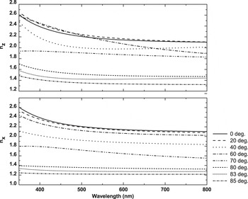
The optical indices and thickness of the as-deposited MoO3 films were obtained by modeling the films as uniaxial layers with two distinct optical indices on glass substrates. Similar to our previous studies of tungsten trioxide GLAD films,Reference Beydaghyan, Bader and Ashrit18, Reference Beydaghyan, Renaud, Bader and Ashrit19 the optical indices of nanostructured MoO3 films diminish with the increase of substrate tilt during deposition, as depicted in Fig. 1. This is due to self-shadowing effect during film growth, which results in higher film porosity, and therefore a lower index of refraction, as a function of substrate tilt during deposition.
Refractive indices of MoO3 films deposited at various substrate tilt angles, with polarization direction normal to the substrate (top), and in the plane of the substrate (bottom).

The birefringence of the films is a result of form anisotropy and results from columnar nature of the films.Reference Beydaghyan, Kaminska, Brown and Robbie20 The incident electromagnetic field is screened to a different degree depending on the relative direction of the field with respect to particle boundaries present in the film. When the constituent particles or aggregates are columnar, the maximum screening of the field occurs when the field direction is perpendicular to the boundaries, and hence gives rise to a diminished value of the corresponding refractive index. The screening of the field is usually small or negligible in the direction parallel to the nanocolumns, resulting in a higher index of refraction in that direction. For the case of no screening, Aspnes finds that a simple volume averaging of dielectric functions is sufficient to obtain the effective dielectric function of the medium.Reference Aspnes21 In the case of a film composed only of one material and void, and away from the absorption edge (i.e., k ≈ 0), the following relationship between porosity, p, effective refractive index, n p, and the refractive index of the constituent particles, n, can be obtainedReference Yoldas and Partlow22
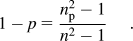
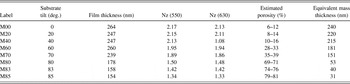
Table I shows a summary of film thickness, optical index at incident wavelengths of 550 and 630 nm, and the estimated porosity of the films. The porosity values are obtained by using the above formula and a value of n = 2.25 ± 0.03 for the optical index of the bulk material at 550 nm.Reference May, Kondrachova, Hahn and Stevenson23 To the extent that the constituent boundaries deviate from the direction of the field, some screening takes place, and so strictly speaking, the above approximation is no longer valid. In such cases, both porosity and screening contribute to lowering of refractive index, and therefore the porosity of the film obtained with the above formula may be slightly overestimated.
Thickness, optical index, and porosity of the films in this study.

The equivalent mass thickness, given in the last column of Table I, gives an estimate of the material available for coloration and is obtained from t(1 − p), where t and p are, respectively, the thickness and porosity of a film.
B. Morphology
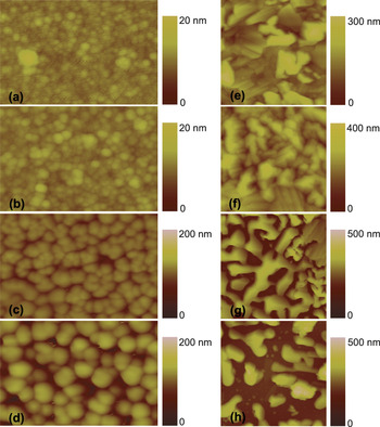
As-deposited films show a granular surface morphology, as indicated by the AFM micrographs in Figs. 2(a)–2(d). This type of morphology is typically observed in films deposited at low energies, with stochastic arrival of vapor molecules and low surface diffusion rate of adatoms, and is consistent with previous studies of films deposited at room temperature with the GLAD technique.Reference Beydaghyan, Bader and Ashrit18 Films deposited with lower substrate tilt angles have smaller grains, typically of 5 to 50 nm in size [Figs. 2(a) and 2(b)]. With the dramatic increase of shadowing at large substrate tilt angles, the grain size of the aggregate particles increases substantially as seen in Figs. 2(c) and 2(d).
Evolution of grain size as a function of tilt angle in nanostructured MoO3 films: AFM images of as-deposited films are presented on the left (image areas are 0.75 × 0.5 μm2), and those of annealed films are shown on the right (image areas are 4 × 4 μm2.) The substrate tilt angles are: (a, e) 0; (b, f) 60; (c, g) 80; and (d, h) 85°.

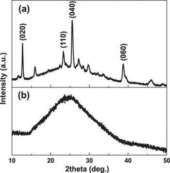
After being annealed at 400 °C, films develop a layered structure with the typical domains of the order of 1 to 5 μm [Figs. 2(e)–2(h)], strongly indicating the formation of α-MoO3, as this phase usually grows as slabs with its 〈010〉 plane exposed.Reference Martinez Guerrero, Vargas Garcia, Santes and Gomez6, Reference Sivakumar, Gopalakrishnan, Jayachandran and Sanjeeviraja10 This is confirmed by the x-ray diffraction data of the MoO3 film deposited at a substrate tilt of 0°, in its as-deposited and annealed state, as shown in Fig. 3. In particular, one notes the presence of peaks of high intensity along 〈020〉, 〈110〉, 〈040〉, and 〈060〉 planes of α-MoO3. The layered morphology is less pronounced in samples that were prepared at higher tilt angles [Figs. 2(c) and 2(d)]. The regions in morphological images may indicate different crystallite orientation or a possible monoclinic (β) phase. Preliminary Raman spectra of the films show the presence of both orthorhombic and monoclinic phases in the annealed samples and provide strong evidence that the nanostructure and overall porosity of the films play a significant role in the evolution of film texture during annealing.
X-ray diffraction of (a) annealed and (b) as-deposited nanostructured MoO3 film, deposited at a substrate tilt of 0°, on glass substrates.

C. Electrochromic response: As-deposited films
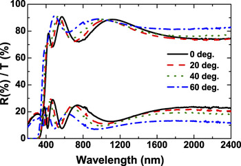
As-deposited films of MoO3 are characterized by high transmission and glossy appearance. Films with higher porosities have much lower refractive indices, higher overall transmission and diminished interference peaks (Fig. 4). The portion of either transmitted or reflected beam that appears as the diffuse component is negligible in as-deposited films before or after lithiation, amounting to less than 3 to 4% in M60 and less than 1% in other samples.
Transmittance and reflectance of as-deposited nanostructured MoO3 films.

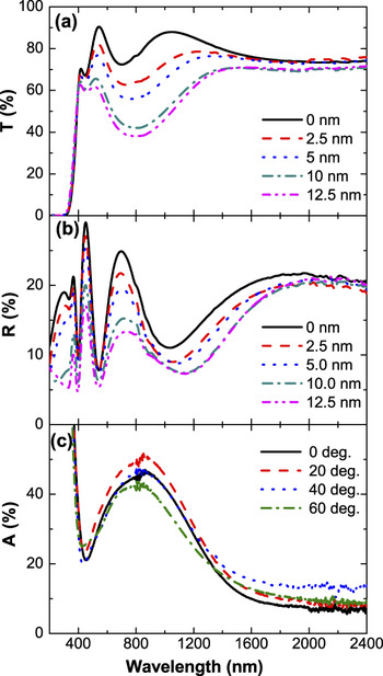
A typical coloration response, that of sample M20 upon lithiation, is shown in Fig. 5. One notes the marked drop in the reflection spectra that accompanies the transmission drop with lithium intercalation, signifying light absorption as the mechanism of coloration. Other samples exhibit similar transmission and reflection drops upon lithiation. The absorption curves, deduced by using α = 100 − T − R, show coloration in visible and near infra-red (NIR) regions, with absorption peaks located at approximately 800 nm [Fig. 5(c)]. One notes the large coloration response of all samples, despite increasing porosity and decreasing amount of material available for intercalation. Note the slightly superior coloration response of sample M20 to that of sample M00, despite having less material available for coloration, and that even sample M60, having porosity of approximately 30% (see Table I) shows an absorption spectra very similar to that of sample M00 [Fig. 5(c)]. The high coloration efficiency of porous samples could indicate the efficacy of higher effective surface area in these films in facilitating the intercalation of lithium atoms.Reference Beydaghyan, Doiron, Haché and Ashrit15, Reference Suzuki and Taga24
Typical (a) transmission and (b) reflectance spectra of an as-deposited MoO3 film, before and after deposition of 2.5, 5, 10, and 12.5 nm of lithium are shown. The substrate tilt angle in this case was 20°. The absorption spectra of as-deposited films with the intercalation of 12.5 nm of lithium are shown in (c).

These are promising results, as the high porosity could indicate the presence of efficient channels for rapid ionic diffusion and intercalation. These channels could make possible the fabrication of devices with rapid electrochromic response, without significant compromise on the magnitude of optical modulation.
D. Electrochromic response: Annealed films
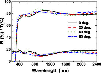
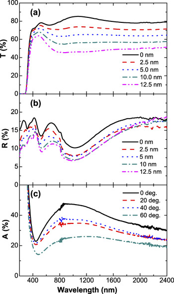
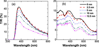
Upon annealing, MoO3 films are still highly transparent, but show diminished interference peaks in both transmission and reflection spectra (Fig. 6). Typical transmission and reflection spectra before and after lithiation are shown in Fig. 7, with the absorption spectra of annealed films shown in Fig. 7(c). We observe an onset of the coloration in the visible region, similar to that of as-deposited films (Fig. 5). However, as opposed to the more selective coloration response of the as-deposited films, the annealed films exhibit significant coloration over a broad wavelength range in the NIR. The uniform coloration of annealed MoO3 films over a broad spectral range is similar to that which we observed in nanocrystalline (annealed) films of WO3.Reference Beydaghyan, Renaud, Bader and Ashrit19 However, unlike the intercalated annealed tungsten trioxide films in which a significant increase in NIR reflection contributed to overall transmission drop,Reference Beydaghyan, Renaud, Bader and Ashrit19 the coloration of annealed molybdenum trioxide films is almost entirely due to absorption and only a slight (in the order of a few percentage) increase in NIR reflection is observed in these films.
Transmittance and reflectance of annealed MoO3 films.

Typical (a) transmission and (b) reflectance spectra of an annealed MoO3 film, before and after deposition 2.5, 5, 10, and 12.5 nm of lithium are shown. The substrate tilt angle in this case was 0°. The absorption spectra of annealed films with the intercalation of 12.5 nm of lithium are shown in (c).

Figure 7(c) also shows the effect of available material (see effective mass thickness in Table I) on the coloration response of annealed samples. This in turn implies that the coloration response of the films is more efficient at lower concentration of intercalated atoms.
The grain boundaries present in annealed films (Fig. 3) give rise to a large diffuse response. Diffuse transmission and reflection spectra, respectively, show peaks as high as 48% and 15% in intensity, with peak positions varying slightly in different samples. The diffuse components of transmission and reflection spectra of a typical sample are shown in Fig. 8.
Diffuse component of the (a) transmitted, and (b) reflected beam of an annealed MoO3 film, deposited at a substrate tilt angle of 0°.

IV. DISCUSSION
The coloration response of both the as-deposited and the annealed MoO3 GLAD films have many common features with the response of the similar films composed of WO3, as previously investigated and reported.Reference Beydaghyan, Bader and Ashrit18, Reference Beydaghyan, Renaud, Bader and Ashrit19 A strong coloration response in nanostructured as-deposited MoO3 films is observed despite the high porosity in these films. The as-deposited films are generally amorphous, with the impurity bands in the Fermi gap and the formation of polarons as the dominant coloration mechanism in these materials.Reference Granqvist1, Reference Berggren, Azens and Niklasson25 As-deposited films of MoO3 show a wavelength selective coloration response, with the maximum efficiency at approximately 800 nm. The transmission drop in these films is accompanied by a decrease in reflection. This behavior is consistent with previous works in the literature.Reference Granqvist1
In the case of annealed films, there are similarities as well as contrasts in the behavior of MoO3 and WO3 films. MoO3 films form much larger grains than WO3 films upon annealing, and the AFM images strongly suggest the presence of large (up to 5 μm) crystalline domains. Upon lithium atom intercalation, the transmission spectra in both oxides indicate a coloration response significantly enhanced in the NIR region, while the reflected spectra show qualitatively different behavior. Annealed WO3 films showed a metallic behavior consistent with Drude model in markedly increased reflection in the NIR (wavelengths greater than 1250 nm) upon intercalation.Reference Beydaghyan, Renaud, Bader and Ashrit19, Reference Yoshida26, Reference Cogan, Plante, Parker and Rauh27 The MoO3 films show decrease of reflection throughout the range of the measurement of our spectrophotometer, with the exception of a slight increase (1–4%) in reflection at wavelengths higher than 1700 nm. However, one notices that the reflection spectra are bunched together at about 2400 nm (0.5 eV). Both oxides have a semiconductor-like band structure with the Fermi energy falling in the band gap.Reference Granqvist1, Reference Sian and Reddy12 With the intercalation of ions and electrons in the crystalline oxides, the excess electrons render the valance band partially filled, causing the intercalated oxide to exhibit metallic behavior, with the refractive indices following the Drude model.Reference Granqvist1 It is possible that the crossover to metallic behavior, i.e., the plasma edge, occurs at a much higher wavelength in MoO3 films than in WO3 films.
V. CONCLUSION
We have investigated the electrochromic response of nanostructured molybdenum trioxide films prepared with the glancing angle deposition technique and have observed a strong coloration response in these films. Upon intercalation of ions, annealed films show a broad coloration response, whereas the response of the as-deposited films is much more wavelength selective and mainly limited to the visible range. Contrary to the case of tungsten oxide films, annealed films of molybdenum oxide do not show a strong increase in NIR reflection upon intercalation.
The strong electrochromic response of the films at comparatively low substrate tilt suggests the suitability of these films for device fabrication, in which a strong and efficient coloration response is desired. As-deposited MoO3 films with their efficient coloration in the visible spectra are more suitable for applications such as display devices, while the annealed MoO3 films showing a broadband modulation in the solar spectral region may be more apt for smart window applications.
ACKNOWLEDGMENTS
We thank Jeff Dahn and Robbie Sanderson of Dalhousie University for the measurement of x-ray diffraction spectra. We acknowledge the invaluable contribution of Pierre St-Onge in the design, fabrication, and commissioning of our GLAD sample manipulator. We also thank Georges Bader for valuable discussions. The financial contributions of Atlantic Innovation Fund (AIF-FIA) and that of the Natural Sciences and Engineering Research Council (NSERC) of Canada are also gratefully acknowledged.