

The last Scottish Ice Sheet (SIS) was the dominant component of the last British–Irish Ice Sheet (BIIS), and for much of its existence extended far beyond the present land area of Scotland. Here we use ‘SIS' to refer to glacier ice nourished in Scotland during the period ∼35–14 ka, which incorporates the later part of Marine Isotope Stage (MIS) 3 and most of MIS 2. During much of this period, the SIS was confluent with ice sourced in England, Wales, Ireland and Norway, but remained an independent, though complex, centre of ice dispersal; there is no convincing evidence that external ice encroached on the present land area of Scotland. We use the abbreviation LGM to denote the last global glacial maximum of ∼26.5 ka to ∼19 ka (P. U. Clark et al. Reference Clark, McCabe, Schnabel, Clark, Freeman, Maden and Xu2009) and LLGM (local last glacial maximum) to refer to the maximum extent of different sectors of the last SIS, some of which reached their outermost limits millennia before others.
Over the past two decades, our understanding of the extent, dynamics and chronology of the SIS has undergone radical transformation. Not only is it now accepted that the ice sheet was much more extensive than previously believed, but it has also been shown that it was drained by fast-flowing ice streams, exhibited marked changes in configuration and flow patterns, and experienced numerous readvances as the ice margin retreated from its outermost reach. This transformation largely reflects the application of new approaches, notably: (1) increasing use of offshore bathymetric, seismostratigraphic and borehole evidence to reconstruct events relating to the extent and retreat of the ice sheet on the continental shelf; (2) the employment of satellite imagery and digital elevation models to establish sequential regional ice-flow directions and landsystems characteristic of former ice streams; (3) increasingly sophisticated analyses of regional lithostratigraphy; (4) the use of terrestrial cosmogenic nuclide (TCN) dating to establish the timing of deglaciation and readvances on land; and (5) numerical modelling of ice-sheet extent and behaviour. An important development has been the collation of all dating evidence relating to the last BIIS (Hughes et al. Reference Hughes, Greenwood and Clark2011) and the integration of this chronological database with terrestrial landform evidence (C. D. Clark et al. Reference Clark, McCabe, Mix and Weaver2004; Evans et al. Reference Evans, Clark and Mitchell2005; Hughes et al. Reference Hughes, Clark and Jordan2010) and offshore moraine sequences to reconstruct the evolution of the entire BIIS (Clark et al. Reference Clark, Hughes, Greenwood, Jordan and Sejrup2012; Hughes et al. Reference Hughes, Clark and Jordan2014, Reference Hughes, Gyllencreutz, Lohne, Mangerud and Svendsen2016).
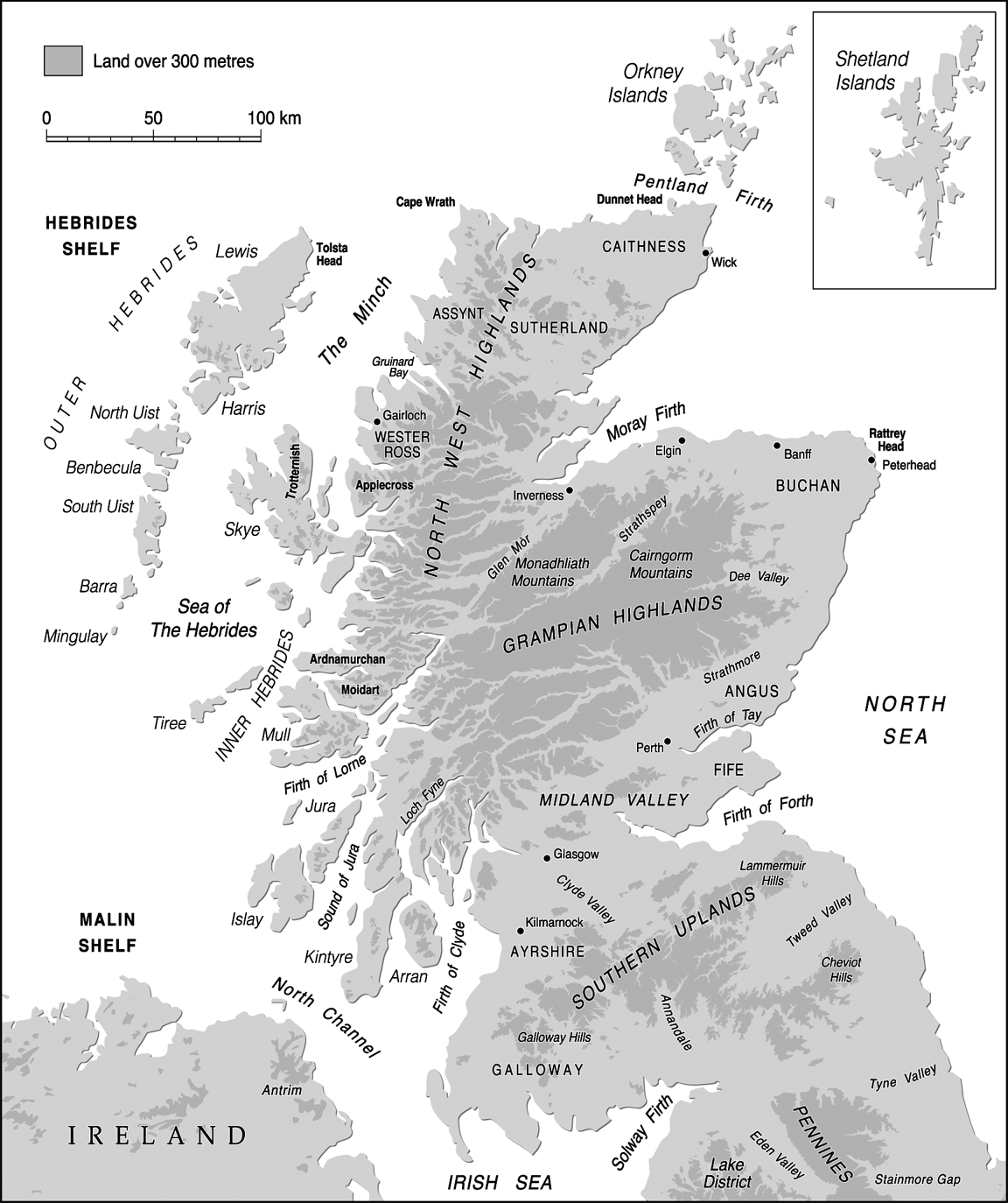
This review considers the impact of these new approaches on our understanding of the SIS, focusing on developments over the past 20 years, many of which nevertheless build on a vast body of earlier research (Sutherland Reference Sutherland1984; Gordon & Sutherland Reference Gordon and Sutherland1993). Following sections considering chronological framework, terminology, dating calibration and the history of ideas concerning the SIS, we first outline current understanding of the pattern of ice-sheet expansion, then the nature of ice-sheet retreat and associated readvance episodes. Details of the stratigraphy associated with these events are given in the reviews by Merritt et al. (Reference Merritt, Hall, Connell and Gordon2018) and Stewart et al. (Reference Stewart2018) in this volume, and are considered here only where essential. This review concludes with the demise, or near-demise, of the SIS during the Lateglacial Interstade (∼14.7–12.9 ka); later glacial events, during the Younger Dryas Stade, are reviewed by Golledge (Reference Golledge2010). Key locations mentioned in the text are identified in Figure 1.
Key locations mentioned in the text.
1. Chronological framework, terminology and dating calibration
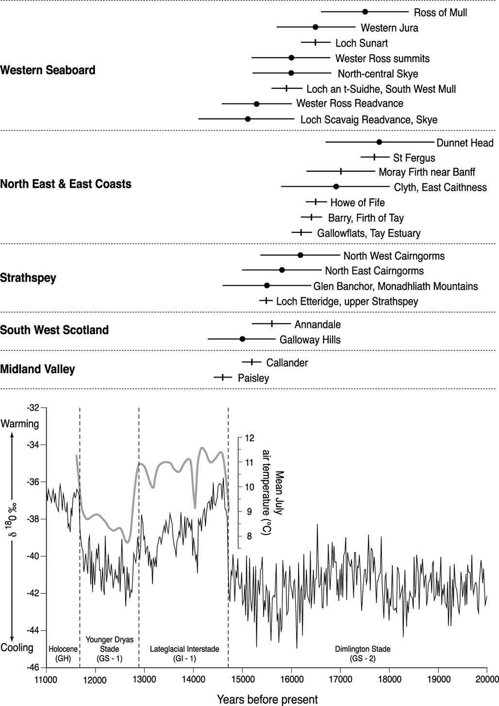
The last glacial stage in Great Britain is termed the Devensian, and is chronologically equivalent to the Weichselian in Europe. Chronostratigraphic subdivision of the Devensian on the basis of terrestrial evidence is poorly constrained, so here we follow the convention of equating subdivisions with marine oxygen isotope stages (MIS) using the temporal boundaries of Lisiecki & Raymo (Reference Lisiecki and Raymo2005): Early Devensian (=MIS 5d–4, ∼109–57 ka; Middle Devensian (=MIS 3, ∼57–29 ka) and Late Devensian (=MIS 2, ∼29–11.7 ka), although some authors place the MIS3/2 boundary at 31 ka or 30 ka. The Late Devensian encompasses Greenland Stadials (GS) 5 to 1, as defined in the Greenland ice core isotope record (∼32.0 ka to 11.7 ka; Rasmussen et al. Reference Rasmussen, Bigler, Blockley, Blunier, Buchart, Clausen, Cvijanovic, Dahl-Jensen, Johnsen, Fischer, Gkinis, Guillevic, Hoek, Lowe, Pedro, Popp, Seierstad, Steffensen, Svensson, Vallelonga, Walker, Wheatley and Winstrup2014) and in Great Britain is subdivided into the Dimlington Stade (∼31–14.7 ka), the Lateglacial (or Windermere) Interstade (∼14.7–12.9 ka) and the Younger Dryas (or Loch Lomond) Stade (∼12.9–11.7 ka). The last SIS began to expand near the end of the Middle Devensian, reached its maximum extent during the Dimlington Stade and had probably fragmented into remnants in the Highlands within a few centuries after the beginning of the Lateglacial Interstade at ∼14.7 ka.
Ages cited below are expressed as ka (thousands of years before present), and mean ages derived from two or more individual ages are uncertainty-weighted means. Cited uncertainties are ±1σ. Uncalibrated radiocarbon ages are cited as 14C a BP or 14C ka and calibrated radiocarbon ages as cal 14C ka. We have recalibrated all radiocarbon ages with the CALIB 7.10 calibration software (Stuiver et al. Reference Stuiver, Reimer and Reimer2016), using the IntCal 13 dataset for terrestrial samples and the Marine 13 dataset for marine samples (Reimer et al. Reference Reimer, Bard and Bayliss2013). We have applied a 400-year reservoir correction for marine shells and foraminifera, whilst acknowledging that reservoir age is likely to have varied (Austin et al. Reference Austin, Telford, Ninnemann, Brown, Wilson, Small and Bryant2011). Calibrated radiocarbon ages are expressed as the ±1σ age range. All TCN exposure ages based on cosmogenic 10Be have been recalibrated using the Lm scaling of the CRONUS-Earth online calculator (Balco et al. Reference Balco, Stone, Lifton and Dunai2008) and the Loch Lomond production rate (LLPR; Fabel et al. Reference Fabel, Ballantyne and Xu2012), which yields a reference production rate of 4.00±0.18 atoms g–1 a–1; other scaling schemes generally produce ages <1.5 % older or <0.5 % younger. Exposure ages based on cosmogenic 36Cl have been calculated using the CRONUScalc online calculator (Marrerro et al. Reference Marrero, Phillips, Borchers, Lifton, Aumer and Balco2016a) and reference production rates of 56.0±4.1, 155±11, 13±3 and 1.9±0.2 atoms 36Cl g–1 a–1, for Ca, K, Ti and Fe, respectively (Schimmelpfennig et al. Reference Schimmelpfennig, Benedetti, Finkel, Pik, Blard, Bourlès, Burnard and Williams2009; Marrero et al. Reference Marrero, Phillips, Caffee and Gosse2016b), using the SA scaling of Lifton et al. (Reference Lifton, Sato and Dunai2014) as this yields ages similar to those produced by independent 10Be exposure dating. For all TCN ages, we cite full (external) uncertainties at ±1σ and assume a sample erosion rate of 1 mm ka–1; assumption of zero erosion for samples analysed using 10Be produces ages ∼1 % younger and assumption of 2 mm ka–1 produces ages ∼1 % older.
All dating techniques used to constrain the timing of glaciation and deglaciation are associated with quantifiable (systematic and random) and unquantifiable (geological) uncertainties. The latter are not included in the cited uncertainty term for any date, but may result in the date being unrepresentative of the event being dated. The sources of geological uncertainty associated with the dating techniques referred to here are reviewed by Small et al. (Reference Small, Clark, Chiverrell, Smedley, Bateman, Duller, Ely, Fabel, Medialdea and Moreton2017b), who provide quality assurance protocols applicable to the use of published dates in ice-sheet reconstructions. In this account, we discuss published dates in terms of their original interpretation and evaluate their significance and representativeness within the context of wider chronological considerations.
2. Evolving ideas concerning the extent of the last Scottish Ice Sheet
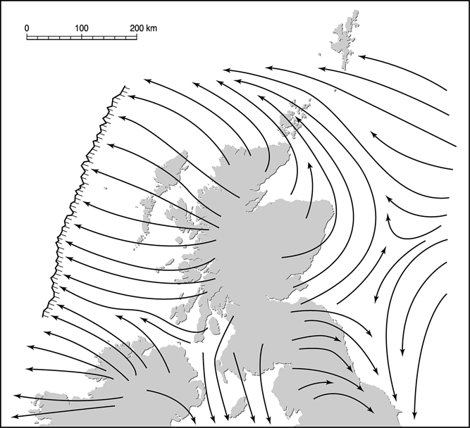
Early research based on erratic transport, till lithology and observations of striae demonstrated that all of Scotland had been glaciated during the Pleistocene. James Geikie (Reference Geikie1876) concluded that “one great sheet of ice enveloped the whole country” and Archibald Geikie (Reference Geikie1901), Peach & Horne (Reference Peach, Horne, Murray and Pullar1910) and Wright (Reference Wright1914) produced maps of ice-sheet extent showing directions of ice flow, with glacier ice terminating westwards at the Atlantic Shelf break and confluence of the SIS and Fennoscandian Ice Sheet (FIS) in the North Sea Basin (NSB) (Fig. 2). Their interpretations were broadly similar to present understanding of former ice extent, but in the absence of dating controls they were unable to demonstrate that the inferred extent of ice cover represented the last ice sheet, rather than an earlier glaciation. The earliest models of the dimensions of the last SIS (Boulton et al. Reference Boulton, Jones, Clayton, Kenning and Shotton1977, Reference Boulton, Smith, Jones and Newsome1985) adopted this interpretation, placing the western limit of Scottish ice near the Atlantic Shelf break and accepting confluence of the SIS and FIS in the NSB.
The last Scottish Ice Sheet as depicted by Peach & Horne (Reference Peach, Horne, Murray and Pullar1910), who envisaged confluence of Scottish and Scandinavian ice in the North Sea Basin, northwestward deflection of ice from Eastern Scotland and the Moray Firth across Caithness and Orkney, and westward termination of the ice sheet at the Atlantic Shelf edge. The flow patterns were based only on terrestrial evidence (striae, erratic carry and lithostratigraphy) as no offshore information was available.

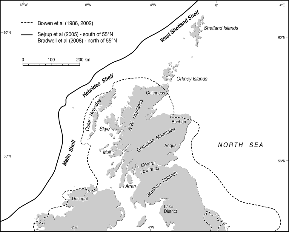
The final decades of the 20th Century witnessed radical reassessment of the dimensions of the SIS. This revision was stimulated by interpretation of the stratigraphy and chronology of offshore sediments in the NSB as indicating that the ice sheet extended only 50–100 km E of the Scottish coast (Holmes Reference Holmes1977; Thomson & Eden Reference Thomson and Eden1977). This interpretation implied that the SIS and FIS were not confluent and thus that Moray Firth ice could not have been diverted NW across Caithness and Orkney, implying that these areas remained outside the limit of the last ice sheet. Evidence for eastward ice movement across the Uists and Benbecula (Coward Reference Coward1977; Peacock & Ross Reference Peacock and Ross1978) and radial ice movement on Harris, Lewis and Shetland (Flinn Reference Flinn1977, Reference Flinn1978a, Reference Flinnb; Von Weymarn Reference Von Weymarn1979) also suggested that these areas were not over-run by the last mainland ice sheet, but nourished independent ice caps. Collectively, these findings prompted Sissons (Reference Sissons1981) to argue that the SIS had been of limited extent, and that Orkney, Caithness and part of NE Scotland lay outside its limits. This ‘restricted ice sheet' model was developed by Sutherland (Reference Sutherland1984) and adopted by Bowen et al. (Reference Bowen, Rose, McCabe and Sutherland1986) in an influential reconstruction that depicted ice-free enclaves in NW Lewis, Orkney, Caithness and NE Scotland (Fig. 3). Their proposed ice-sheet limits were employed to constrain a second generation of ice-sheet models (Boulton et al. Reference Boulton, Peacock, Sutherland and Craig1991; Lambeck Reference Lambeck1995) and were accepted by some researchers for two decades (Bowen et al. Reference Bowen, Phillips, McCabe, Knutz and Sykes2002; C. D. Clark et al. Reference Clark, McCabe, Mix and Weaver2004; Fretwell et al. Reference Fretwell, Smith and Harrison2008).
Changing views of the extent of the northern sector of the last British–Irish Ice Sheet. The dashed line represents the LGM limit of the last ice sheet depicted by Bowen et al. (Reference Bowen, Rose, McCabe and Sutherland1986, Reference Bowen, Phillips, McCabe, Knutz and Sykes2002). The solid line represents the approximate limit of the last ice sheet as depicted by Sejrup et al. (Reference Sejrup, Hjelstuen, Dahlgren, Haflidason, Kuijpers, Nygård, Praeg, Stoker and Vorren2005) S of 55°N and Bradwell et al. (Reference Bradwell, Stoker, Golledge, Wilson, Merritt, Long, Everest, Hestvik, Stevenson, Hubbard, Finlayson and Mathers2008b) N of 55°N.
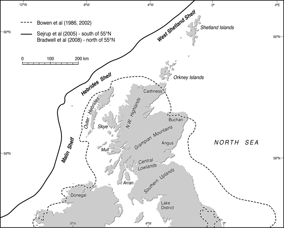
The ‘restricted ice sheet' model was soon contested. The evidence favouring an ice-free enclave in Lewis and termination of the last ice sheet across Caithness and NE Scotland was challenged (Hall & Whittington Reference Hall and Jarvis1989; Hall & Bent Reference Hall and Bent1990; Hall Reference Hall1995, Reference Hall, Gilbertson, Kent and Grattan1996), and seismostratigraphic, borehole and dating evidence from the Hebrides and Shetland shelves was interpreted as indicating much greater westward extension of the last ice sheet (Davies et al. Reference Davies, Dobson and Whittington1984; Selby Reference Selby1989; Peacock et al. Reference Peacock, Austin, Selby, Graham, Harland and Wilkinson1992; Fyfe et al. Reference Fyfe, Long and Evans1993; Stoker et al. Reference Stoker, Hitchen and Graham1993). Sejrup et al. (Reference Sejrup, Haflidason, Aarseth, King, Forsberg, Long and Rokoengen1994) revived the argument for the confluence of the SIS and FIS in the NSB, a hypothesis subsequently vindicated by evidence for grounded ice occupying this area during the LGM (Sejrup et al. Reference Sejrup, Hjelstuen, Dahlgren, Haflidason, Kuijpers, Nygård, Praeg, Stoker and Vorren2005; Carr et al. Reference Carr, Holmes, van der Meer and Rose2006; Graham et al. Reference Graham, Lonergan and Stoker2007). The upper limits of erosion by the last ice sheet on mountains in NW Scotland were shown to indicate extension of ice cover far beyond the limits of the ‘restricted ice sheet' model (Ballantyne et al. Reference Ballantyne, McCarroll, Nesje, Dahl and Stone1998a, Reference Ballantyne, McCarroll, Nesje, Dahl, Stone and Fifieldb). Finally, bedrock and boulder samples from Orkney, Caithness and NE Scotland yielded post–LGM TCN ages within the (recalibrated) age range ∼21–16 ka, demonstrating that these areas were over-run by the SIS (Phillips et al. Reference Phillips, Hall, Ballantyne, Binnie, Kubik and Freeman2008; Ballantyne Reference Ballantyne2010). Such findings forced abandonment of the ‘restricted ice sheet' model in favour of a much larger ice sheet that in many respects resembles that proposed a century earlier.
3. Ice-sheet expansion and maximum extent
Recent reconstructions of the maximum extent of the last BIIS (Bradwell et al. Reference Bradwell, Stoker, Golledge, Wilson, Merritt, Long, Everest, Hestvik, Stevenson, Hubbard, Finlayson and Mathers2008b; Chiverrell & Thomas Reference Chiverrell and Thomas2010; Gibbard & Clark Reference Gibbard and Clark2011; Clark et al. Reference Clark, Hughes, Greenwood, Jordan and Sejrup2012; Hughes et al. Reference Hughes, Clark and Jordan2014, Reference Hughes, Gyllencreutz, Lohne, Mangerud and Svendsen2016) depict extension of Scottish ice to the Atlantic Shelf edge, and southward into the Irish Sea Basin (ISB) and across northern England. To the east, they show confluence with the FIS, flow of ice from the Moray Firth northwestward across Caithness and Orkney, and southeastward diversion of ice from eastern Scotland in the western NSB. The only outer terminus of glacier ice nourished solely in Scotland, therefore, lay along the Atlantic Shelf between ∼56°N and ∼61°N (Fig. 3), as in all other sectors it was confluent with ice nourished in Norway, northern England, Wales and Ireland, and such confluence zones migrated during ice-sheet expansion and retreat. The evidence favouring this interpretation is outlined below.
Reconstructed flowlines indicate that as the ice sheet expanded, ice from different centres of dispersal met and interacted, ice divides built up and migrated, and the directions of ice movement changed in response. As the ice sheet grew, ice streams (zones of fast flow) developed and assumed dominance in discharging ice towards the ice-sheet margins, probably triggering drawdown of the ice surface. Moreover, ice expansion was asynchronous: different sectors of the SIS reached their maximum extent at different times. Below, we consider the evidence relating to timing of the initial growth of the SIS and a reconstruction of the overall pattern of ice-sheet expansion, before focusing on the detailed evidence in three sectors: (1) southern and SW Scotland; (2) eastern Scotland, Orkney, Shetland and the NSB; and (3) western Scotland, the Hebrides and the Atlantic Shelf.
3.1. Initial expansion of the last ice sheet
The extent of glacier ice in Scotland prior to expansion of the last ice sheet is unknown, but may be inferred from the flux of ice-rafted detritus (IRD) of British provenance in cores retrieved from the NE Atlantic. Investigation of the magnetic signature of IRD in core MD95-2006 from the distal northern part of the Barra–Donegal Fan (BDF) by Peters et al. (Reference Peters, Walden and Austin2008) indicates very limited contribution from Scotland prior to ∼38.5 ka, but an increased contribution thereafter, suggesting expansion of marine-terminating glaciers nourished in the Highlands. Core MD04-2882 from the Rockall Trough contains evidence of IRD derived from a nascent BIIS after ∼43 ka (Hibbert et al. Reference Hibbert, Austin, Leng and Gatliff2010) and suggests the intermittent presence of marine-terminating glaciers in western Scotland until ∼35 ka and the continuous presence of a tidewater ice margin thereafter. This evidence implies that an ice cap or icefield extended to sea level in the western Highlands several millennia before its expansion to cover low ground and the adjacent shelves.
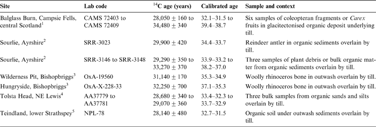
Radiocarbon ages for organic material buried under till deposited by the SIS (Table 1) indicate that most low ground was ice free before ∼35 cal 14C ka and possibly as late as ∼32 cal 14C ka. Faunal and floral assemblages from the sites at Balglass Burn and Sourlie indicate cold tundra conditions and permafrost (Bos et al. Reference Bos, Dickson, Coope and Jardine2004; Brown et al. Reference Brown, Rose, Coope and Lowe2007), consistent with the coeval presence of glaciers in the Highlands. The Balglass site lies only ∼20 km from the Highland edge, yet the mean age of six samples from this site indicates that it was not over-run by Highland ice until after 36.0–34.9 cal 14C ka, and the youngest age suggests that it may not have been over-run until after ∼32 cal 14C ka. Of the uppermost four radiocarbon ages obtained by Whittington & Hall (Reference Whittington and Hall2002) for bulk samples from organic-rich sands and silts buried under till at Tolsta Head in eastern Lewis, the youngest (30.8–30.1 cal 14C ka) probably reflects contamination, as the underlying three samples yielded consistent ages averaging 33.4–32.8 cal 14C ka; there is also some uncertainty as to whether the overlying till was deposited by Outer Hebrides ice or mainland ice. Collectively, the limiting ages for ice expansion across low ground suggest that during the final millennia of MIS 3 glacier ice expanded from mountain source areas, over-running most low ground after ∼35 ka and possibly two or three millennia later.
Radiocarbon ages relating to the expansion of the last Scottish Ice Sheet

Calibrated ages represent ±1σ range. Sources: 1Brown et al. (Reference Brown, Rose, Coope and Lowe2007); 2Bos et al. (2004); 3Jacobi et al. (Reference Jacobi, Rose, MacLeod and Higham2009); 4Whittington & Hall (Reference Whittington and Hall2002); the uppermost age in the Tolsta Head sequence may reflect contamination and is excluded; 5FitzPatrick (Reference FitzPatrick1965); this date should be regarded as minimal (Sissons Reference Sissons1981; Hall et al. Reference Hall1995).
The timing of ice expansion across the NSB is broadly consistent with the ages obtained from terrestrial sites. Three radiocarbon ages for shells in marine sediments overlain by till within a core from the North Sea Plateau, ∼330 km NE of Shetland, yielded (in stratigraphic order) ages of 34.6–34.0, 34.5–33.8 and 34.1–33.3 cal 14C ka, implying that this area remained ice-free until at least ∼34 ka (Rise & Rokoengen Reference Rise and Rokoengen1984; Sejrup et al. Reference Sejrup, Haflidason, Aarseth, King, Forsberg, Long and Rokoengen1994). Similarly, samples of foraminifera and shell fragments in glacially deformed glacimarine sediments in core BGS BH 04/01 from the Witch Ground Basin ∼175 km NE of Rattray Head produced ages of 35.0–33.9, 39.1–30.9, 35.0–29.1 and 35.8–31.3 cal 14C ka (Graham et al. Reference Graham, Lonergan and Stoker2010). Although three of these ages have large uncertainties, the median ages associated with these samples (34.8–32.2 cal 14C ka) suggest that the Witch Ground Basin remained largely ice-free until ∼34–33 ka.
3.2. The overall pattern of ice-sheet expansion
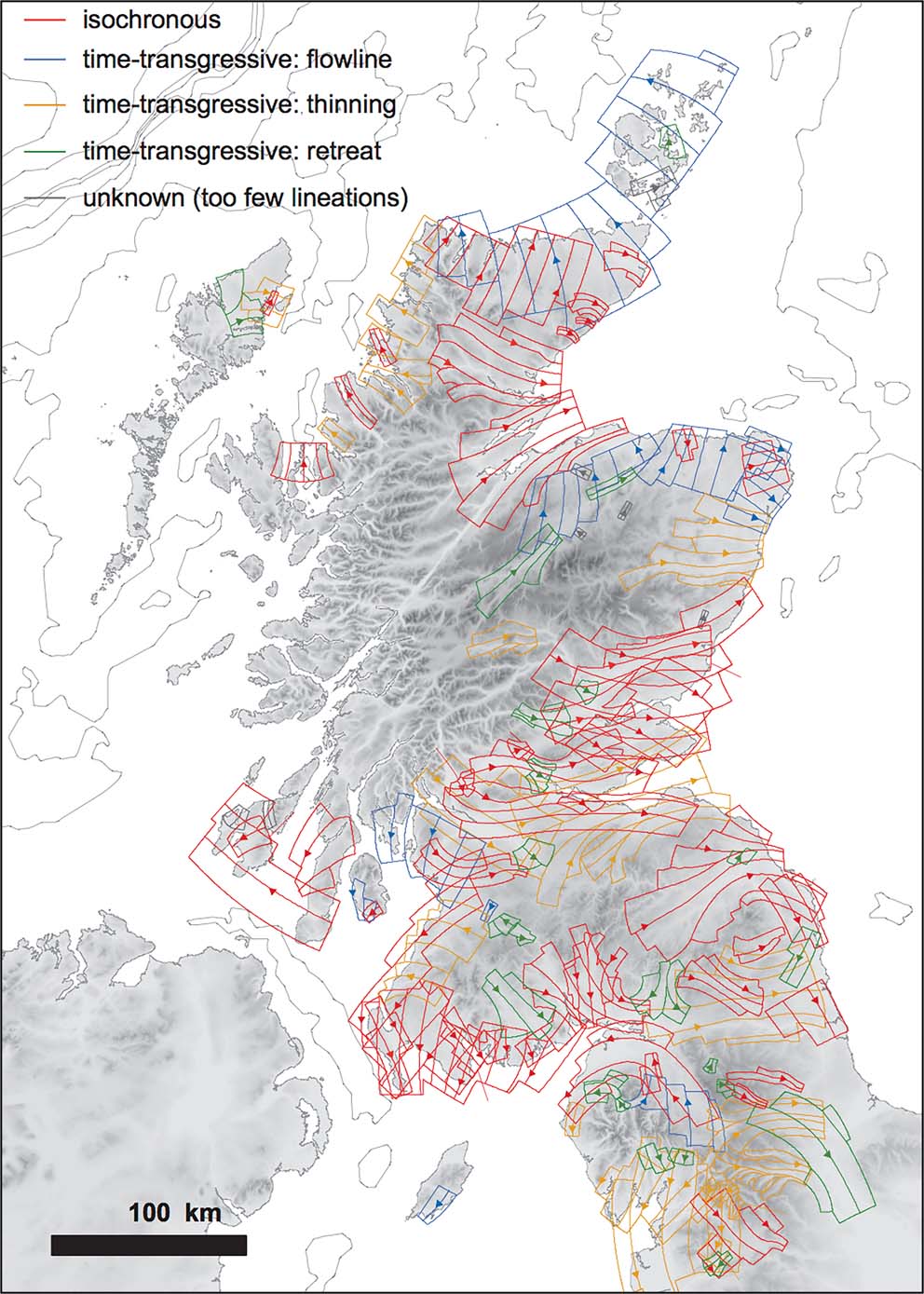
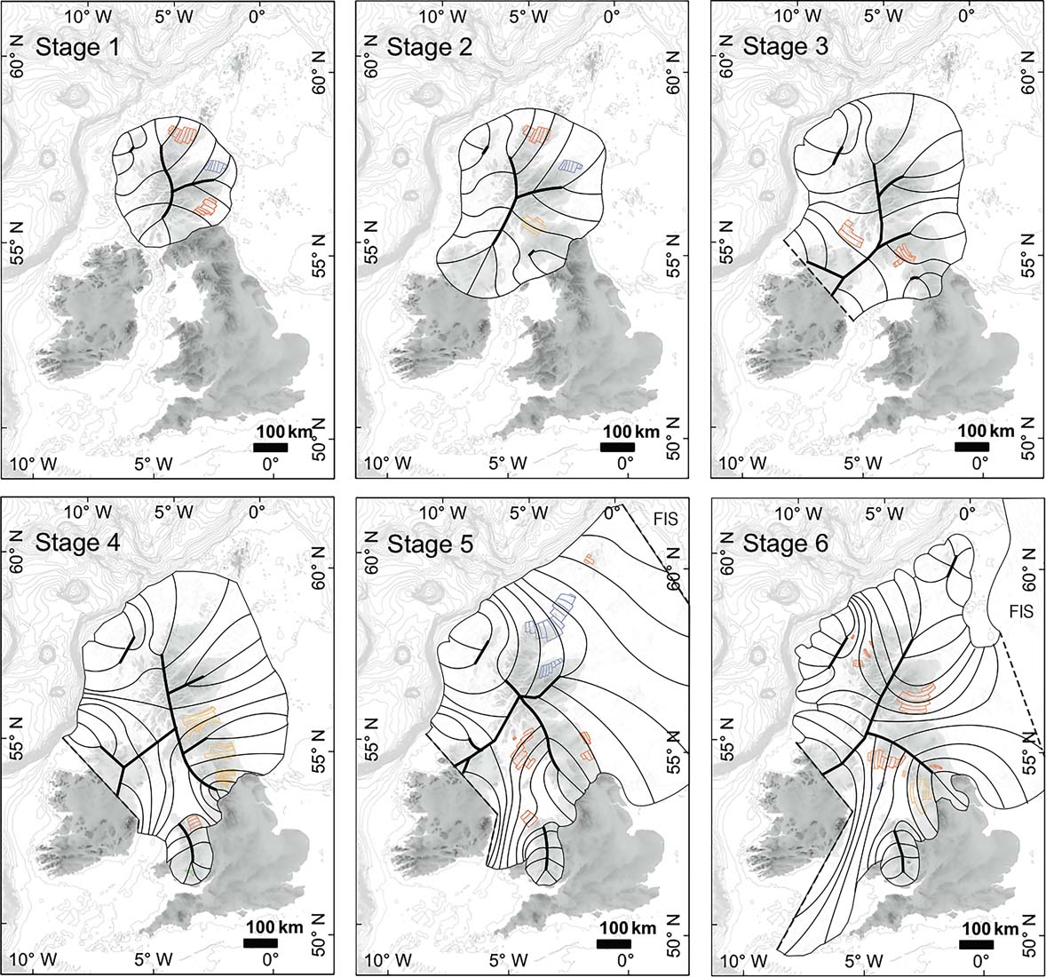
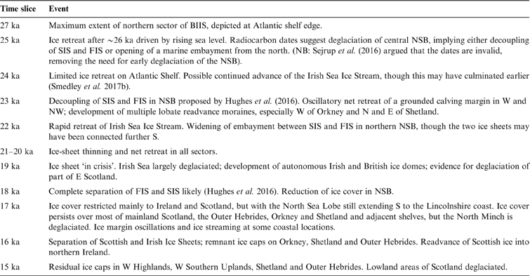
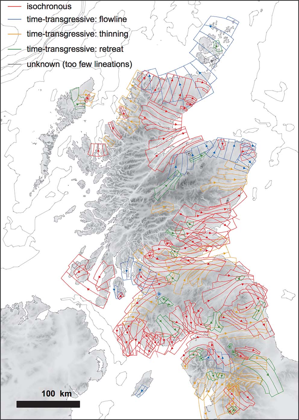
Understanding of the evolution of the SIS has been transformed by remote mapping of landforms indicative of the direction of former ice movement (drumlins, streamlined drift ridges, mega-scale glacial lineations (MSGLs), ribbed moraine and meltwater channels) and the grouping of such landforms into discrete flowsets that represent different phases of ice movement. Overprinting of one flowset by another indicates the relative chronology of ice flow trajectories (Fig. 4), though it does not exclude the possibility that the oldest flowsets identified in this way represent pre-Late Devensian ice flow directions, and some supposed flowsets in areas of thin drift cover may be influenced by underlying rock structure (Hall & Riding Reference Hall and Riding2016; Merritt et al. Reference Merritt, Connell and Hall2017). Using this approach, and incorporating data on erratic transport and offshore landforms, Hughes et al. (Reference Hughes, Clark and Jordan2014) developed a first-order reconstruction of the stages of ice sheet expansion (Fig. 5). Stage 1 of their reconstruction envisages congruent ice caps over the Highlands and Outer Hebrides, and approximates conditions around 35–32 ka, when ice enveloped the Midland Valley. Stage 2 depicts the initial build-up of an ice divide over SW Scotland and the extension of Scottish ice deep into the Irish Midlands. By stages 3 and 4, thickening and expansion of the Irish Ice Sheet and Southern Uplands ice dome has resulted in the development of an ice divide between SW Scotland and Ireland; at this time the ice margin is inferred to have approached or reached the Atlantic Shelf edge. Stage 5 depicts the SIS terminating westward at the Atlantic Shelf edge and an eastward confluence with the FIS, forcing ice flowing eastward from Scotland to divert northwestward across Caithness and Orkney and southeastward across NE England and into the southern NSB. This stage approximates the maximum extent of glacier ice sourced in Scotland, which Hughes et al. (Reference Hughes, Clark and Jordan2014) suggested occurred between 28 ka and 26 ka. Southward ice expansion, however, is depicted as continuing during stage 6, by which time they depict the retreat of the northern ice margin, the development of an ice cap over Shetland and the partial decoupling of the SIS and FIS.
Flowsets of the northern and central parts of the last ice sheet in Great Britain as interpreted by Hughes et al. (Reference Hughes, Clark and Jordan2014). Red flowsets are interpreted to be isochronous and those in other colours are inferred to be time-transgressive. Reproduced from Hughes et al. (Reference Hughes, Clark and Jordan2014) Quaternary Science Reviews 89, 148–168, with permission from Elsevier. © 2014 Elsevier Ltd.
Stages in the growth of the last British Ice Sheet inferred by Hughes et al. (Reference Hughes, Clark and Jordan2014) from flowset and offshore evidence. Thick lines represent former ice divides or saddles, and thin lines represent flowlines inferred from flowsets and offshore landform data. Reproduced from Hughes et al. (Reference Hughes, Clark and Jordan2014) Quaternary Science Reviews 89, 148–168, with permission from Elsevier. © 2014 Elsevier Ltd.
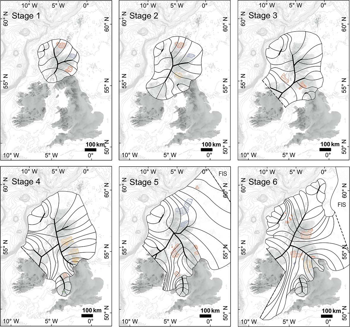
Notable features of the pattern of ice-sheet build up proposed by Hughes et al. (Reference Hughes, Clark and Jordan2014) include the persistence of a migratory N–S ice divide extending southward from the NW Highlands, and the development of an ice divide between SW Scotland and NE Ireland, which limited the flow of Scottish ice into the ISB. They acknowledged that the timing of ice-sheet build-up is poorly constrained, and that their reconstruction (Fig. 5) may conflict with more detailed evidence in particular sectors. It nevertheless shows reasonable congruence with numerical models of the pattern of ice-sheet build-up (Boulton & Hagdorn Reference Boulton and Hagdorn2006; Hubbard et al. Reference Hubbard, Bradwell, Golledge, Hall, Patton, Sugden, Cooper and Stoker2009; Patton et al. Reference Patton, Hubbard, Andreassen, Winsbarrow and Stroeven2016) and represents a first approximation that forms a basis for future refinement.
3.3. The southern sector of the ice sheet
The evolution of the southern sector of the SIS has been reconstructed through identification of cross-cutting and overprinted flowsets that indicate migrating ice sheds and major changes in ice movement during ice-sheet expansion. This approach was pioneered in this sector by Salt & Evans (Reference Salt and Evans2004) and subsequently developed by Finlayson et al. (Reference Finlayson, Merritt, Browne, Merritt, McMillan and Whitbread2010, Reference Finlayson, Fabel, Bradwell and Sugden2014) for west-central Scotland, and Evans et al. (Reference Evans, Livingstone, Vieli and Ó Cofaigh2009) and Livingstone et al. (Reference Livingstone, Ó Cofaigh and Evans2008, Reference Livingstone, Ó Cofaigh and Evans2010b, Reference Livingstone, Evans, Ó Cofaigh, Davies, Merritt, Huddart, Mitchell, Roberts and Yorke2012, Reference Livingstone, Roberts, Davies, Evans, Ó Cofaigh and Gheorghiu2015) for northern England and southern Scotland. Palaeoflow directions reconstructed from landforms are complemented by evidence provided by striae, erratic transport and lithostratigraphy. The methodology employed is essentially similar to that employed by Hughes et al. (Reference Hughes, Clark and Jordan2014; Fig. 4), and it is noteworthy that the flowsets derived independently by three groups of researchers are broadly similar.
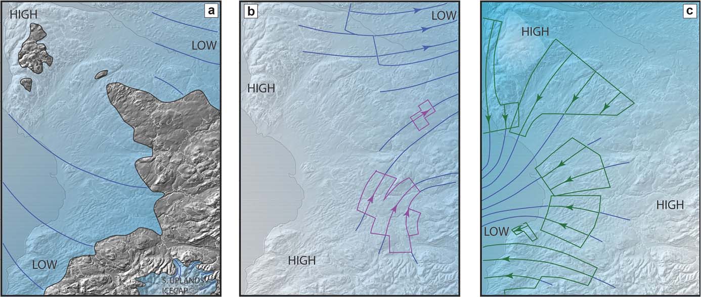
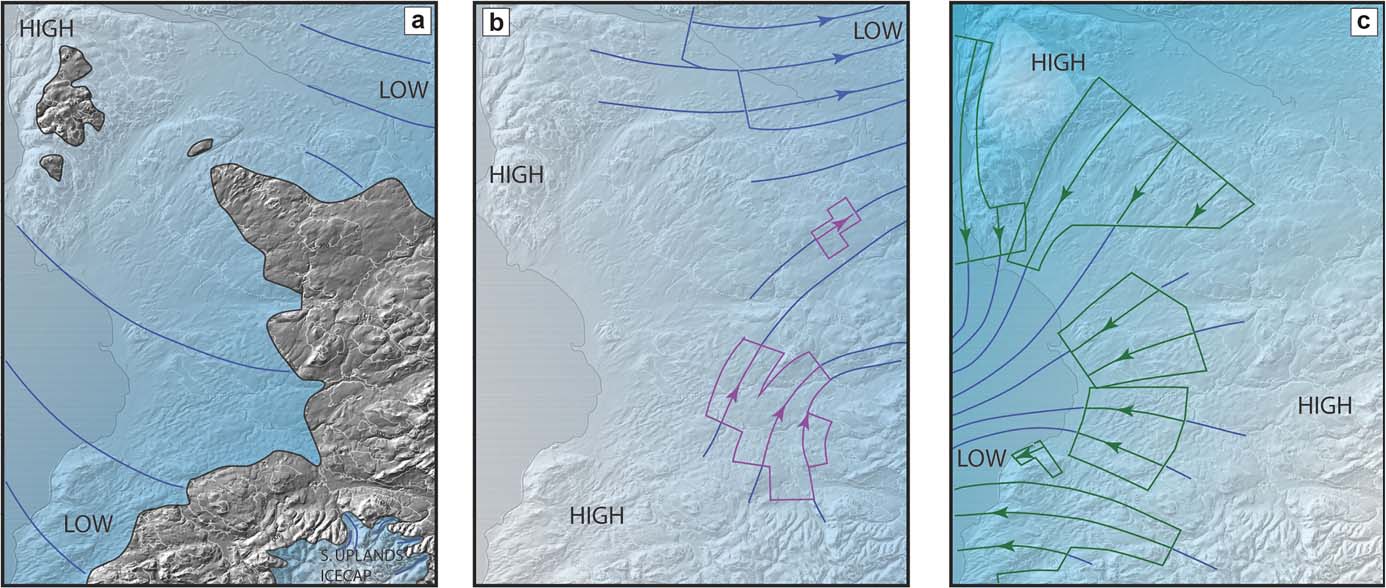
Finlayson et al. (Reference Finlayson, Merritt, Browne, Merritt, McMillan and Whitbread2010, Reference Finlayson, Fabel, Bradwell and Sugden2014) showed that initial expansion (after ∼35 ka) of ice nourished in the SW Highlands resulted in ice movement eastward across the Midland Valley and southward down the Firth of Clyde, eventually meeting the expanding Southern Uplands ice cap in south Ayrshire (Fig. 6a). Flowset evidence indicates that during this stage Scottish ice may have penetrated up to 200 km southwestward into the Irish Midlands (Greenwood & Clark Reference Greenwood and Clark2009), and the presence of Ailsa Craig microgranite erratics along the coasts of Wales and eastern Ireland (Sissons Reference Sissons1967; McCabe & Ó Cofaigh Reference McCabe and Ó Cofaigh1995) suggests that ice from the SW Highlands reached the ISB. Subsequent expansion and thickening of Southern Uplands ice, however, led to its confluence with the Irish Ice Sheet and the formation of a persistent but migratory ice divide across the North Channel between NE Ireland and SW Scotland, so that ice N of the divide was rerouted westward across the Malin Shelf (Finlayson et al. Reference Finlayson, Fabel, Bradwell and Sugden2014) and only ice nourished in the Galloway Hills flowed south into the ISB. A N–S-trending ice divide also developed across the Firth of Clyde from the SW Highlands to the western Southern Uplands, feeding ice movement both westward across the Malin Shelf and eastward across the Midland Valley (Fig. 6b). The flowset evidence mapped by Finlayson et al. (Reference Finlayson, Merritt, Browne, Merritt, McMillan and Whitbread2010) suggests that this divide subsequently migrated ∼60 km eastward (Fig. 6c), possibly in response to drawdown of ice streaming westward across the Malin Shelf.
Stages in the evolution of the last ice sheet in west central Scotland identified by Finlayson et al. (Reference Finlayson, Merritt, Browne, Merritt, McMillan and Whitbread2010): (a) advance of ice from the SW Highlands across the Firth of Clyde, Ayrshire and the Midland Valley; (b) establishment of an ice divide between the SW Highlands and western Southern Uplands results in eastward flow of ice across the Midland Valley (c) eastward migration of the ice divide results in dominantly westward ice movement, feeding the Hebrides Ice Stream. Reproduced from Finlayson et al. (Reference Finlayson, Merritt, Browne, Merritt, McMillan and Whitbread2010) Quaternary Science Reviews 29, 969–988, with permission from Elsevier. © 2009 NERC.
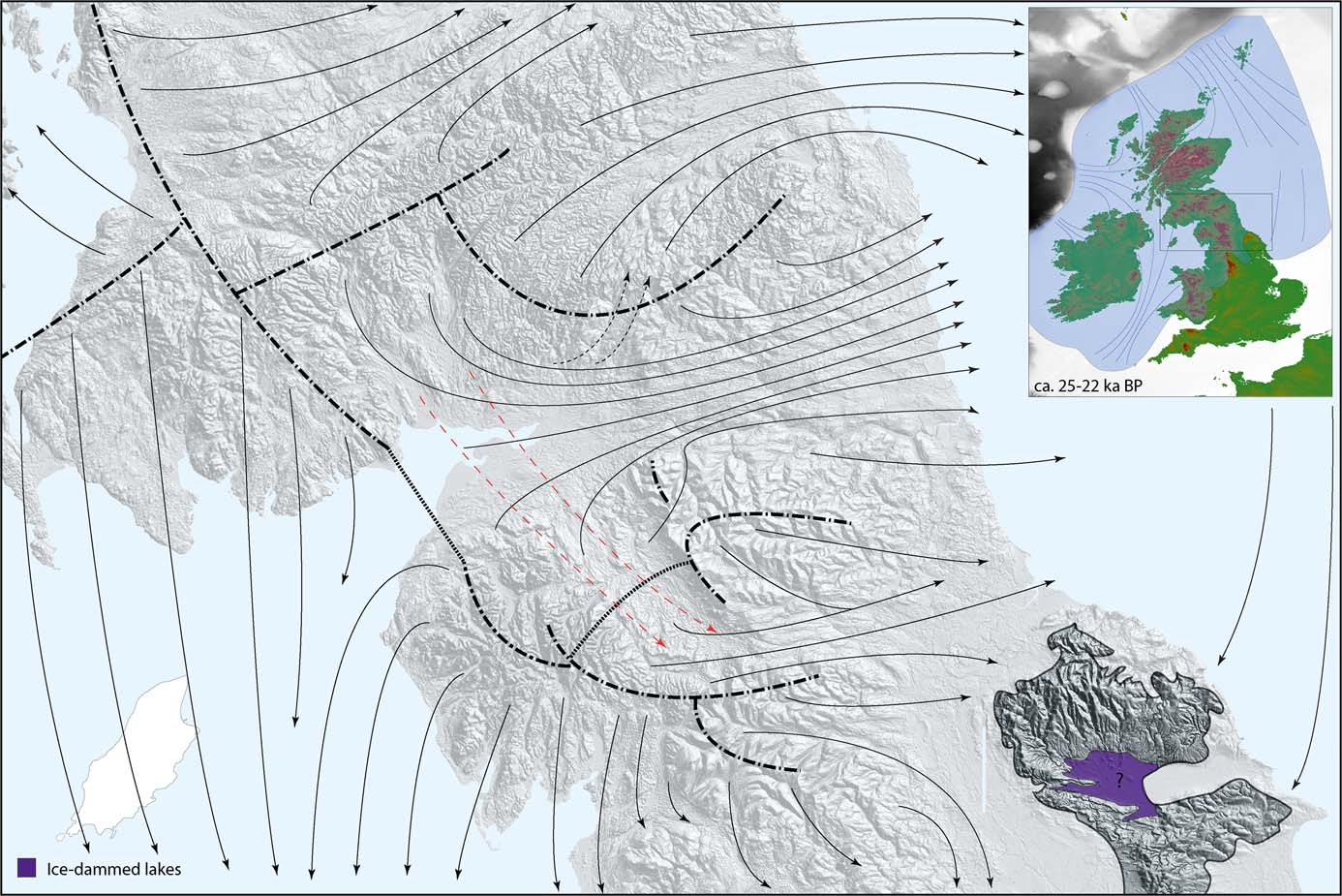
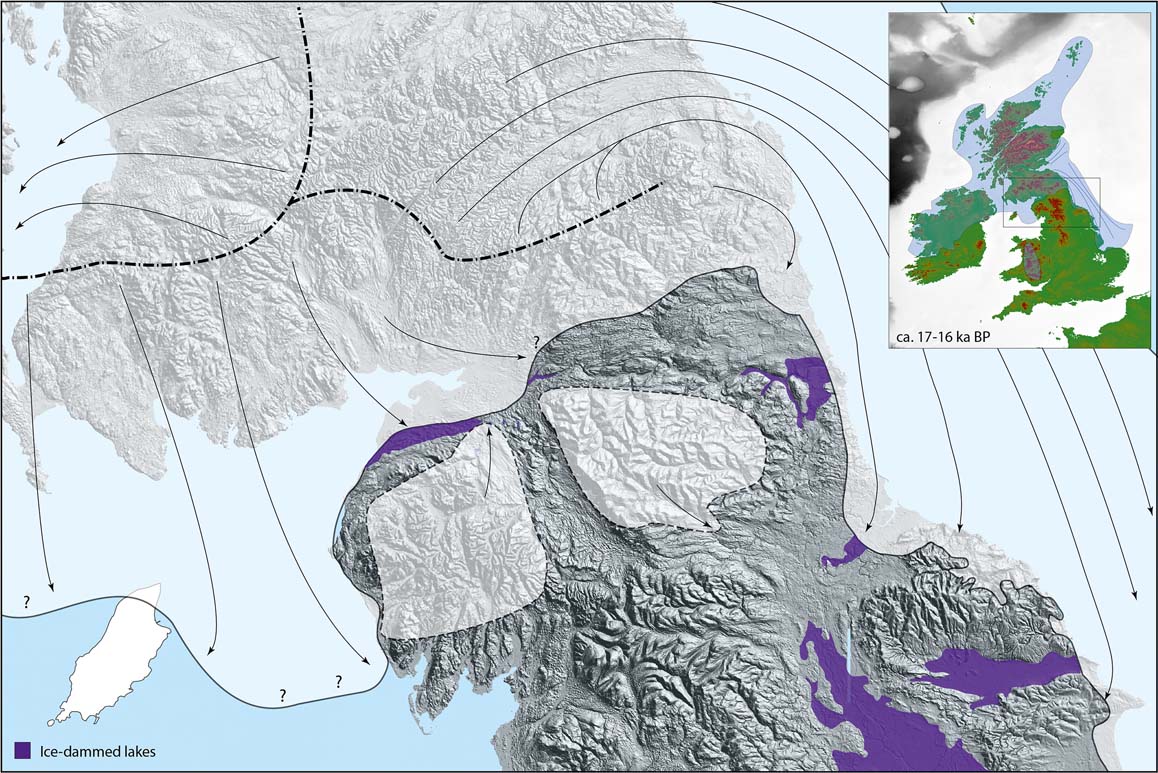
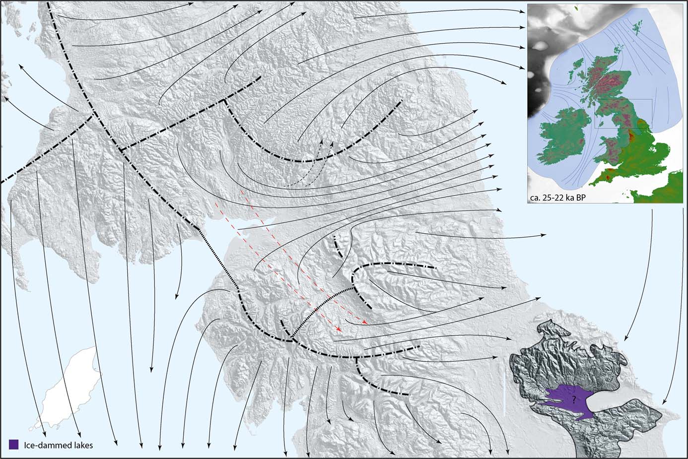
Using a similar approach, Livingstone et al. (Reference Livingstone, Ó Cofaigh and Evans2008, Reference Livingstone, Ó Cofaigh and Evans2010b, Reference Livingstone, Evans, Ó Cofaigh, Davies, Merritt, Huddart, Mitchell, Roberts and Yorke2012, Reference Livingstone, Roberts, Davies, Evans, Ó Cofaigh and Gheorghiu2015) and Evans et al. (Reference Evans, Livingstone, Vieli and Ó Cofaigh2009) reconstructed the evolution of the last ice sheet in the Southern Uplands and northern England. Ice from the Galloway Hills and Southern Uplands initially predominated, carrying erratics into the Eden Valley and possibly crossing the Stainmore Gap through the Pennines. Subsequent development of a NW–SE ice divide across the Solway Firth from SW Scotland to the Lake District (Fig. 7) represents the continuation of that identified by Finlayson et al. (Reference Finlayson, Merritt, Browne, Merritt, McMillan and Whitbread2010; Fig. 6b) farther north. This divide separated southward ice flow from Galloway into the ISB and eastward flow of ice from the Southern Uplands and Lake District into the Tyne valley. During the LLGM, high ground in the Southern Uplands and the Cheviots appears to have been occupied by cold-based ice domes (Mitchell Reference Mitchell2007, Reference Mitchell2008) that fed ice flowing eastward across the Midland Valley and southwards into the Tweed valley (Everest et al. Reference Everest, Bradwell and Golledge2005). Ice flowing eastward through the Midland Valley to the Firth of Forth was diverted SE near the coast, joining that from the Tweed and the Tyne and extending southwards to NE Yorkshire (Fig. 7). Livingstone et al. (Reference Livingstone, Evans, Ó Cofaigh, Davies, Merritt, Huddart, Mitchell, Roberts and Yorke2012) suggested that this general pattern of ice movement persisted for several millennia. Southward-flowing ice from Galloway continued to flow into the ISB, joining ice from the Lake District, Wales and Ireland to form the Irish Sea Ice Stream (ISIS). Scourse & Furze (Reference Scourse and Furze2001) placed the southernmost extent of the ISIS at a transition from subglacial till to glacimarine facies at ∼49.5°S, but Praeg et al. (Reference Praeg, McCarron, Dove, Ó Cofaigh, Scott, Monteys, Facchin, Romeo and Coxon2015) have presented lithostratigraphic and geophysical evidence suggesting that the ISIS extended >150 km farther south, potentially reaching the Celtic Sea shelf edge as a result of short-lived surging. Bayesian modelling based on published age data suggests that the ISIS achieved its maximum southern reach between ∼24.3 and 23.0 ka (McCarroll et al. Reference McCarroll, Stone, Ballantyne, Scourse, Hiemstra, Evans and Fifield2010; Chiverrell et al. Reference Chiverrell, Thrasher, Thomas, Lang, Scourse, McCarroll, Clark, Ó Cofaigh, Evans and Ballantyne2013), but TCN and luminescence dating evidence implies that it impinged on the Scilly Isles at ∼26–25 ka (Smedley et al. Reference Smedley, Chiverrell, Ballantyne, Burke, Clark, Duller, Fabel, McCarroll, Scourse, Small and Thomas2017a).
Ice flow in southern Scotland and northern England during the maximum expansion of the BIIS, as depicted by Livingstone et al. (Reference Livingstone, Evans, Ó Cofaigh, Davies, Merritt, Huddart, Mitchell, Roberts and Yorke2012). Thick dash-dotted lines represent ice divides, arrows indicate ice-flow vectors and dashed arrows in red indicate possible alternative ice-flow vectors. The inset shows location of this sector within the BIIS as depicted by Clark et al. (Reference Clark, Hughes, Greenwood, Jordan and Sejrup2012). Reproduced from Livingstone, S. J. et al. (Reference Livingstone, Evans, Ó Cofaigh, Davies, Merritt, Huddart, Mitchell, Roberts and Yorke2012) Earth-Science Reviews 111, 25–55, with permission from Elsevier. © 2011 Elsevier B.V.
3.4. The northeastern and eastern sector of the ice sheet
Although it is generally accepted that the SIS was confluent with the FIS in the NSB, there remains uncertainty regarding the pattern and sequence of ice movement during both ice-sheet expansion and retreat. Here we consider first the terrestrial evidence for key areas (Shetland, Orkney, Caithness and NE Scotland), then the changing interpretations of the pattern of ice movement in the NSB during the LLGM.
3.4.1. Shetland
Interpretation of the Late Devensian glacial history of Shetland has polarised around two viewpoints: (1) that the islands were over-ridden by ice moving westward towards the Atlantic shelf edge, but later developed an independent ice cap; and (2) that the archipelago nourished a persistent ice cap of sufficient size to repel invasion by ice advancing from the NSB. The first interpretation, promoted by Peach & Horne (Reference Peach and Horne1879), was accepted in recent syntheses based mainly on glacial bedforms on the adjacent shelf (Bradwell et al. Reference Bradwell, Stoker, Golledge, Wilson, Merritt, Long, Everest, Hestvik, Stevenson, Hubbard, Finlayson and Mathers2008b; Graham et al. Reference Graham, Stoker, Lonergan, Bradwell, Stewart, Ehlers, Gibbard and Hughes2011; Clark et al. Reference Clark, Hughes, Greenwood, Jordan and Sejrup2012), and was supported by interpretation of onshore streamlined bedforms in parts of the archipelago (Golledge et al. Reference Golledge, Finlayson, Bradwell and Everest2008) and research on glacitectonic fabrics (Carr & Hiemstra Reference Carr and Hiemstra2013). These interpretations contrast with the work of Flinn (Reference Flinn1977, Reference Flinn1978a, Reference Flinn2009), who demonstrated that striae, plucked bedrock and roches moutonnées exhibit a consistent radial pattern away from an ice divide aligned N–S along the spine of the Shetlands.
Review of the field evidence by Hall (Reference Hall2013) supports the independent ice cap hypothesis. He argued that the pattern of streamed bedforms is consistent with divergent ice flow beneath a Shetland ice cap, and that glacitectonic structures interpreted as indicating ice flow from the NSB (Carr & Hiemstra Reference Carr and Hiemstra2013) are unreliable. He noted also the absence of E–W streamlined bedforms or ice-moulded bedrock across central Shetland and, tellingly, the absence of erratics or marine shells derived from the NSB in the tills of eastern Shetland. Development of an independent Shetland ice cap that persisted during the LLGM is also evident in numerical simulations of the last BIIS (Hubbard et al. Reference Hubbard, Bradwell, Golledge, Hall, Patton, Sugden, Cooper and Stoker2009) and supported by the extension of till of Shetland provenance up to ∼110 km E of the archipelago (Peacock Reference Peacock1995). It is also consistent with the pattern of retreat indicated by submarine moraine banks, which show that ice margins converged on Shetland after the LLGM (Bradwell et al. Reference Bradwell, Stoker, Golledge, Wilson, Merritt, Long, Everest, Hestvik, Stevenson, Hubbard, Finlayson and Mathers2008b; Clark et al. Reference Clark, Hughes, Greenwood, Jordan and Sejrup2012). The pattern of offshore moraine banks and data on offshore till lithology led Hall (Reference Hall2013) to conclude that during the LLGM the Shetland Ice Cap extended NW–SE over at least 160 km to the Atlantic shelf edge, diverting the FIS northwestward and ice from the Moray Firth and NSB across northern Orkney.
3.4.2. Caithness and Orkney
The last glaciation of Caithness has traditionally been interpreted as a two-stage event in which initial ice movement northeastward from Sutherland was succeeded by N to NW movement of Moray Firth ice, which deposited an extensive grey till containing marine shells (Peach & Horne Reference Peach and Horne1881; Hall & Whittington Reference Hall and Jarvis1989). Lithostratigraphic research by Hall et al. (Reference Hall, Auton, Michie, McL Pearson and Riding2011) and Hall & Riding (Reference Hall and Riding2016) indicates a more complex event stratigraphy in which the radial outflow of ice from ice centred over the hills of the Sutherland–Caithness border was succeeded in turn by (1) the retreat of the ice margin from the north coast; (2) an initial advance of Moray Firth ice northwestward across the Caithness plain; and (3) the retreat of the ice margin, represented by deposition of fan gravels at the north coast. This was followed by the main northwestward advance of Moray Firth ice across Caithness, which deflected the flow of Highland ice northwards and deposited the widespread shelly till (the Forse Till). Excluding outliers, six TCN ages obtained by Phillips et al. (Reference Phillips, Hall, Ballantyne, Binnie, Kubik and Freeman2008) for the deglaciation of sites in northern and SE Caithness range from 20.5±3.2 ka to 16.0±1.1 ka, indicating that the main advance of Moray Firth ice across Caithness occurred during the LLGM.
On Orkney, the evidence provided by striae, glacial lineations, erratic transport and till containing marine shell fragments and palynomorphs demonstrates a general ESE to WNW movement of glacier ice across the archipelago (Peach & Horne Reference Peach and Horne1880; Sutherland Reference Sutherland1984; Hall et al. Reference Hall, Riding and Brown2016b). Eight TCN ages for low ground have produced post-LGM 10Be exposure ages (Phillips et al. Reference Phillips, Hall, Ballantyne, Binnie, Kubik and Freeman2008), confirming that the last movement of glacier ice across the archipelago occurred during the Late Devensian; a single (recalibrated) TCN age of 20.6±1.2 ka for a boulder at 467 m altitude on Ward Hill indicates the complete over-running of all high ground. Unlike Shetland, there appears to be no evidence for a former independent ice cap on Orkney (Hall et al. Reference Hall, Riding and Brown2016b).
Hall et al. (Reference Hall, Riding and Brown2016b) identified three tills on Orkney, and related these to three phases of ice movement. The earliest till appears to record ice movement from a more southerly direction than the overlying widespread Scara Taing Till, the stratigraphic equivalent of the Forse Till of Caithness. This till was emplaced by ice moving SE–NW, and in northern Orkney contains rare far-travelled erratics that can be linked to sources in the Northern Highlands, the Inner Moray Firth, the Grampian Highlands, Fennoscandia and possibly eastern Scotland, implying a complex history of transport and reworking. The uppermost till was apparently deposited by a late readvance of ice across low ground. Noting that the palynomorph assemblages in the Orkney tills are dominated by material sourced from the inner Moray Firth and the shelf SE of Orkney, Hall et al. (Reference Hall, Riding and Brown2016b) argued that the rare Scandinavian erratics detected in Orkney till are reworked, and that the last FIS did not impinge on these islands.
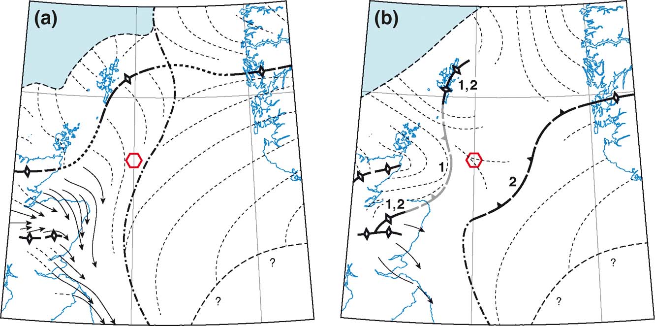
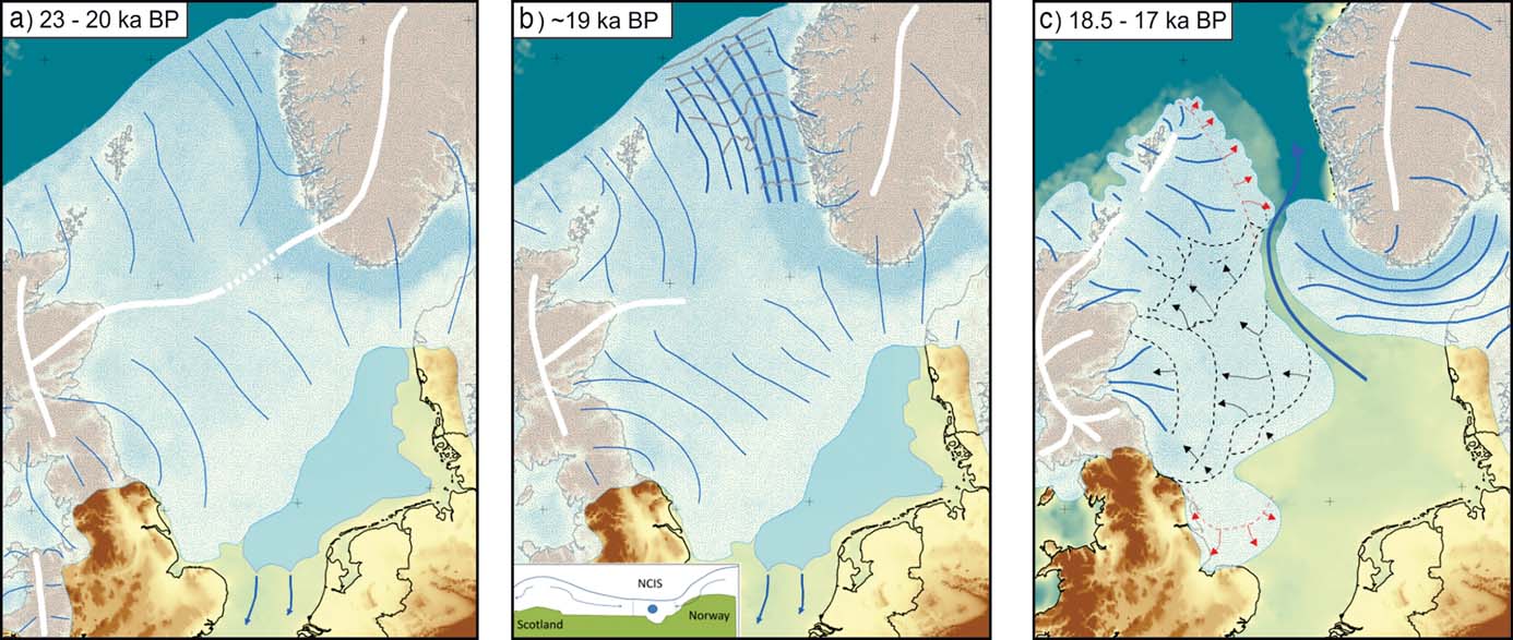
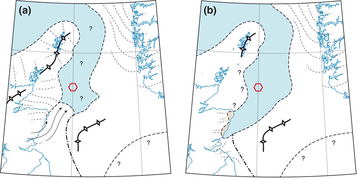
Although Hall & Riding (Reference Hall and Riding2016) and Hall et al. (Reference Hall, Riding and Brown2016b) acknowledged that expansion of the FIS and Shetland Ice Cap could have been responsible for the deflection of Moray Firth ice NW across Caithness and Orkney, they advocated other scenarios for such deflection, such as eastwards shift of the former ice shed or, somewhat confusingly, “… ice congestion in the northern North Sea”. An alternative solution is that a SW–NE aligned ice divide (Sejrup et al. Reference Sejrup, Clark and Hjelstuen2016) or migrating ice divide (Merritt et al. Reference Merritt, Connell and Hall2017) developed between NE Scotland and SW Norway during the LLGM (Fig. 8) forcing ice from the Moray Firth to flow NW toward the Atlantic Shelf edge.
Sequential stages in the evolution of the eastern sector of the SIS as depicted by Merritt et al. (Reference Merritt, Connell and Hall2017): (a) southeastward diversion of Moray Firth ice from an ice divide linking Caithness and the Shetland Ice Cap; (b) northwestward re-routing of Moray Firth ice by a receding ice shed linking Buchan and Shetland (position 1) that subsequently retreated to position 2. Dashed lines represent flow directions. Thick lines with open diamonds denote ice divides; those with filled ticks denote a receding ice shed. The red hexagon represents the position of the Witch Ground Basin. From Merritt et al. (Reference Merritt, Connell and Hall2017) Journal of Quaternary Science 32, 276–294. © 2016 John Wiley & Sons, Ltd.

3.4.3. NE Scotland
The record of glaciation in NE Scotland (the Moray Firth lowlands and Buchan) has been reviewed by Merritt et al. (Reference Merritt, Connell and Hall2017), who attempted to reconcile published data on erratic transport and striae with the detailed lithostratigraphy of Merritt et al. (Reference Merritt, Auton, Connell, Hall and Peacock2003), the pattern of subglacial bedforms mapped by Hughes et al. (Reference Hughes, Clark and Jordan2010) and the flowsets derived from these bedforms (Hughes et al. Reference Hughes, Clark and Jordan2014) in an event stratigraphy. The earliest stage identified by Merritt et al. (Reference Merritt, Connell and Hall2017) is represented by till deposited by ice flowing from the NW across the north coast of Buchan. Stage 2 in their scheme (Fig. 8a) involved southeasterly ice flow across the coastal lowlands of Moray and Buchan into central and eastern Buchan. They suggested a confluence with southeasterly ice movement from the eastern Grampians across Angus at this time, and envisaged contemporaneity with ice movement NW across Caithness and Orkney. During stages 3 and 4, ice flow from the Moray Firth apparently swung to the ENE, before curving northwestward across Orkney. To accommodate this switch, Merritt et al. (Reference Merritt, Connell and Hall2017) suggested a progressive eastwards migration of an ice divide (from position 1 in Fig. 8b to position 2) and establishment of a NW-flowing ice stream in the Orkney–Shetland Channel at this time, with the ice margin at the Atlantic Shelf edge. Their reconstruction of these stages depicts the persistence of a Shetland Ice Cap as argued by Hall (Reference Hall2013), as well as ice from the Eastern Grampians flowing eastwards to southeastwards across eastern Buchan, Angus and Fife. Farther inland, the absence of schist erratics on the central Cairngorms (Sugden Reference Sugden1970) and the radial dispersal of Cairngorm granite erratics (Sutherland Reference Sutherland1984) suggest that this massif acted as a centre of ice dispersal and persisted as a local ice dome that diverted ice from the Grampians into Strathspey and the Dee valley.
3.4.4. The North Sea Basin (NSB)
Confirmation that the central and northern NSB were completely covered by conjoined ice sheets during the LLGM comes from several sources. Radiocarbon ages of molluscs and foraminifera within undisturbed marine or glacimarine sediments overlying glacially-deformed marine sediments or till range from ∼26.5 to ∼17.2 cal 14C ka (Sejrup et al. Reference Sejrup, Haflidason, Aarseth, King, Forsberg, Long and Rokoengen1994, Reference Sejrup, Nygård, Hall and Haflidason2009, Reference Sejrup, Hjelstuen, Nygård, Haflidason and Mardal2015; Graham et al. Reference Graham, Lonergan and Stoker2010). Though the oldest ages may be stratigraphically unrepresentative (Sejrup et al. Reference Sejrup, Clark and Hjelstuen2016), these dates confirm that the underlying sediments were deformed or emplaced by Late Devensian (Late Weichselian) ice, and the younger ages indicate marine sedimentation following ice-sheet retreat prior to ∼18–17 ka. Microfabric analyses of key formations in the NSB indicate complete ice cover during the LLGM (Carr et al. Reference Carr, Holmes, van der Meer and Rose2006) and mapping of moraines and subglacial tunnel valleys from bathymetric and seismostratigraphic data (Lonergan et al. Reference Lonergan, Maidment and Collier2006; Bradwell et al. Reference Bradwell, Stoker, Golledge, Wilson, Merritt, Long, Everest, Hestvik, Stevenson, Hubbard, Finlayson and Mathers2008b; Clark et al. Reference Clark, Hughes, Greenwood, Jordan and Sejrup2012) also indicates complete ice cover across the northern NSB during the LLGM. Finally, research by Graham et al. (Reference Graham, Lonergan and Stoker2007, Reference Graham, Lonergan and Stoker2010) based on 3D reflection seismic data covering the Witch Ground Basin (Fig. 8) has revealed NW-trending buried mega-scale glacial lineations, 5–20 km long, interpreted as demonstrating the confluence of the SIS and FIS, and the development of a former ice stream that flowed NW towards the Orkney–Shetland channel or SE towards the central NSB. The timing of ice build-up in the NSB remains uncertain. Analysis of the available chronological data by Hughes et al. (Reference Hughes, Gyllencreutz, Lohne, Mangerud and Svendsen2016) suggested that parts of the NSB may have been ice free as late as 29–28 ka, but that the central and northern NSB were completely ice-covered by 27 ka.
There are conflicting views regarding the pattern of ice movement in the NSB during the LLGM. The traditional view was that the expanding FIS acted as a barrier that forced eastward moving ice from NE Scotland to turn northwestward across Caithness and Orkney, and ice from SE Scotland to turn southeastward then southward toward the English coast. A refinement of this interpretation is that the NW-trending MSGLs in the Witch Ground Basin identified by Graham et al. (Reference Graham, Lonergan and Stoker2007, Reference Graham, Lonergan and Stoker2010) represent a confluence zone between the FIS and SIS that extended NW across northern Orkney, implying that Shetland was over-run by ice from Norway (Bradwell et al. Reference Bradwell, Stoker, Golledge, Wilson, Merritt, Long, Everest, Hestvik, Stevenson, Hubbard, Finlayson and Mathers2008b; Chiverrell & Thomas Reference Chiverrell and Thomas2010; Hughes et al. Reference Hughes, Clark and Jordan2014; Fig. 9). Clark et al. (Reference Clark, Hughes, Greenwood, Jordan and Sejrup2012), however, depicted a broad ice divide extending from NE Scotland to SW Norway, an interpretation consistent with modelling experiments (Boulton & Hagdorn Reference Boulton and Hagdorn2006; Patton et al. Reference Patton, Hubbard, Andreassen, Winsbarrow and Stroeven2016). This view was developed by Sejrup et al. (Reference Sejrup, Clark and Hjelstuen2016), who argued that the MSGLs in the Witch Ground Basin were produced by ice streaming to the SE rather than NW. The migratory ice shed proposed by Merritt et al. (Reference Merritt, Connell and Hall2017; Fig. 8b) represents a variant of this model consistent with switching ice-flow directions on land. The concept of a SE-migrating divide spanning the northern NSB appears to accommodate the available terrestrial and offshore evidence better than the ‘confluence' model (Fig. 9), but remains to be confirmed.
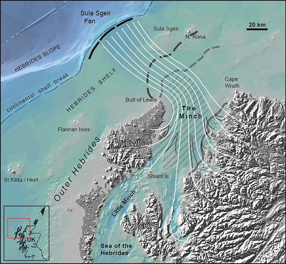
Confluence of the SIS and FIS in the NSB during the LLGM as depicted by Bradwell et al. (Reference Bradwell, Stoker, Golledge, Wilson, Merritt, Long, Everest, Hestvik, Stevenson, Hubbard, Finlayson and Mathers2008b), with hypothesised flow lines. Dark shading depicts the inferred confluence zone (CZ) and arrows show the orientations of mega-scale glacial lineations. Hatching represents the approximate areas occupied by shelf-edge fans. Also depicted is diversion of ice from western Scotland into the Minch and Hebrides Ice Streams by the Outer Hebrides Ice Cap. From Bradwell et al. (Reference Bradwell, Stoker, Golledge, Wilson, Merritt, Long, Everest, Hestvik, Stevenson, Hubbard, Finlayson and Mathers2008) Earth-Science Reviews 88, 207–226. © 2008 NERC. Reproduced with permission from Elsevier B.V.

3.5. Western Scotland, the Hebrides and the Atlantic Shelf
The evidence provided by striae, erratic distribution and blockfields indicates that during ice-sheet build-up, the islands of Skye, Mull and Arran developed cold-based mountain ice caps that diverted the flow of mainland ice and probably remained centres of ice dispersal through the lifetime of the SIS, though all other islands in the Inner Hebrides were ultimately over-run by ice flowing westward from the Scottish Mainland (Bailey et al. Reference Bailey, Clough, Wright, Richey and Wilson1924; Tyrrell Reference Tyrrell1928; Gemmell Reference Gemmell1973; Dahl et al. Reference Dahl, Ballantyne, McCarroll and Nesje1996; Ballantyne & McCarroll Reference Ballantyne, McCarroll, Nesje and Dahl1997; Ballantyne Reference Ballantyne1999; Finlayson et al. Reference Finlayson, Fabel, Bradwell and Sugden2014; Ballantyne et al. Reference Ballantyne, Benn, Bradwell, Small, Ballantyne and Lowe2016). A larger independent ice cap formed over the Outer Hebrides. Mapping of striae and ice-moulded bedrock by Flinn (Reference Flinn1978b), Von Weymarn (Reference Von Weymarn1979) and Peacock (Reference Peacock1984, Reference Peacock, Ehlers, Gibbard and Rose1991) demonstrated former radial ice movement on Lewis and Harris, though occurrences of shelly tills and mainland erratics indicate that mainland ice impinged on eastern Lewis at some stage, and probably crossed northernmost Lewis (Peacock Reference Peacock1984). Striae, ice moulding and erratic transport imply that a N–S-aligned ice divide developed along the western margin of the Uists and Benbecula (Coward Reference Coward1977; Flinn Reference Flinn1978b; Peacock & Ross Reference Peacock and Ross1978; Selby Reference Selby1989). Preservation of blockfields and tors on mountain summits on Harris and South Uist suggests that these were occupied by cold-based ice throughout much or all of the Late Devensian (Ballantyne & McCarroll Reference Ballantyne and McCarroll1995; Ballantyne & Hallam Reference Ballantyne and Hallam2001). The Outer Hebrides Ice Cap appears to have acted as a centre of ice dispersal throughout the evolution of the SIS, feeding ice W across the Hebrides Shelf (Selby Reference Selby1989; Stoker et al. Reference Stoker, Hitchen and Graham1993; Ballantyne et al. Reference Ballantyne, Ó Cofaigh, Coxon, McCarron and Mitchell2017), NE into the Minch Ice Stream (Bradwell et al. Reference Bradwell, Stoker and Larter2007), and southward to feed the Hebrides Ice Stream (Howe et al. Reference Howe, Dove, Bradwell and Gafeira2012; Dove et al. Reference Dove, Arosio, Finlayson, Bradwell and Howe2015; Fig. 9).
The evidence for extension of the SIS to the Atlantic Shelf edge has been inferred from the stratigraphy of large submarine shelf-edge fans (trough-mouth fans), and the distribution and alignment of moraine banks at or near the shelf edge. Four fans abut the shelf edge: the Barra–Donegal Fan (BDF; ∼6300 km2); the Sula Sgeir Fan (SSF; ∼3750 km2); and the smaller Rona Wedge and Foula Wedge (Fig. 9). Deposition of glacigenic sediment on the SSF has been linked to a former ice stream, the Minch Ice Stream (Stoker & Bradwell Reference Stoker and Bradwell2005; Bradwell et al. Reference Bradwell, Stoker and Larter2007; Bradwell & Stoker Reference Bradwell and Stoker2015b) and the BDF acted as depocentre for sediment deposited by converging ice from western Scotland (the Hebrides Ice Stream) and Ireland (Dunlop et al. Reference Dunlop, Shannon, McCabe, Quinn and Doyle2010; Howe et al. Reference Howe, Dove, Bradwell and Gafeira2012; Ó Cofaigh et al. Reference Ó Cofaigh, Dunlop and Benetti2012; Finlayson et al. Reference Finlayson, Fabel, Bradwell and Sugden2014; Dove et al. Reference Dove, Arosio, Finlayson, Bradwell and Howe2015). The link between the Rona and Foula Wedges, submarine troughs and former ice streams is less clear, though the latter may have acted as a depocentre for ice flowing westward through the Orkney–Shetland channel (Fig. 9).
The advance of the ice margin toward the edge of the Malin Shelf is indicated by the lithostratigraphy and ice-rafted debris (IRD) flux recorded in core MD95–2006, a 30 m-long sediment core recovered from the distal northern part of the BDF. At 21.5 m depth within this core there is an abrupt change from hemipelagite and muddy contourite to glacimarine mud with sandy turbidites, which has been interpreted as indicating the proximity of the ice margin (Kroon et al. Reference Kroon, Shimmield, Austin, Derrick, Knutz and Shimmield2000; Knutz et al. Reference Knutz, Austin and Jones2001). This change is accompanied by a marked increase in basaltic IRD derived from the Cenozoic igneous provinces of western Scotland and NE Ireland. Radiocarbon dating of polar and subpolar foraminifera recovered from this core suggests that the onset of ice-proximal glacimarine conditions occurred shortly after ∼30 cal14 C ka, at the MIS 3/2 transition, though the precise timing of maximum ice extent is difficult to define (Wilson et al. Reference Wilson, Austin and Jansen2002; Bradwell et al. Reference Bradwell, Stoker, Golledge, Wilson, Merritt, Long, Everest, Hestvik, Stevenson, Hubbard, Finlayson and Mathers2008b). Based on this record, and associated geophysical data (Knutz et al. Reference Knutz, Jones, Austin and van Weering2002), it has been inferred that ice feeding the BDF reached its maximum extent at ∼27 ka, generating turbiditic flows on the fan (Wilson & Austin Reference Wilson and Austin2002; Scourse et al. Reference Scourse, Haapaniemi, Colmenero-Hidalgo, Peck, Hall, Austin, Knutz and Zahn2009). This proposition may be supported by a marked increase in IRD flux in deep-ocean core MD04-2822, from a location distal to the BDF, at ∼27.4 ka, though this could also represent partial ice-margin collapse or surging behaviour (Hibbert et al. Reference Hibbert, Austin, Leng and Gatliff2010). The SSF also comprises marine or glacimarine muds alternating with packages of glacigenic mass-flow deposits and sandy turbidites, the latter indicating the proximity of the former ice-sheet margin (Stoker & Holmes Reference Stoker and Holmes1991; Stoker Reference Stoker1995; Baltzer et al. Reference Baltzer, Holmes and Evans1998), and sediment sequences on the Rona and Foula Wedges also demonstrate ice-proximal deposition, probably during MIS 2 (Stoker et al. Reference Stoker, Hitchen and Graham1993, Reference Stoker, Leslie, Scott, Briden, Hine, Harland, Wilkinson, Evans and Ardus1994). Arrival of the ice margin at or near the West Shetland Shelf break may be indicated by increased IRD flux at ∼29 ka in deep-ocean core MD04-2829 from the Rosemary Bank (58.95°N, 09.57°W; Scourse et al. Reference Scourse, Haapaniemi, Colmenero-Hidalgo, Peck, Hall, Austin, Knutz and Zahn2009). Collectively, the available dating evidence appears to place the arrival of the Hebrides and Minch ice streams on the outer shelf within the period 30–27 ka. The latter date has been assumed by several authors, but it seems possible that these ice streams may have reached the outer shelf edge 2–3 ka earlier, depending on the interpretation of the lithostratigraphy and IRD flux in deep-ocean cores.
In this context, 10Be exposure ages obtained for samples from eight glacially-transported boulders on the island of North Rona on the Shetland shelf (59.1°N, 05.8°W) are interesting. These indicate the timing of retreat of the ice margin from the outer shelf, and yielded a reported mean age of 24.8±2.7 ka (Everest et al. Reference Everest, Bradwell, Stoker and Dewey2013). Recalibration produces individual ages of 34.0 ± 2.0 ka to 23.4±1.4 ka; excluding three outliers, the weighted mean age of the remaining five samples is 28.7±1.4 ka. This appears to imply both the extension of the ice margin in this sector and its subsequent retreat before ∼29–28 ka. This conclusion should be treated with caution, however, because of the large dating uncertainty, and in the light of research suggesting that 10Be exposure ages for sites at the periphery of former ice sheets may be compromised by subsurface production of 10Be by deeply-penetrating muons, yielding exposure ages that may be ‘too old', even when they exhibit good internal agreement (Briner et al. Reference Briner, Goehring, Mangerud and Svendsen2016; Smedley et al. Reference Smedley, Scourse, Small, Hiemstra, Duller, Bateman, Burke, Chiverrell, Clark, Davies, Fabel, Gheorghiu, McCarroll, Medialdia and Xu2017b).
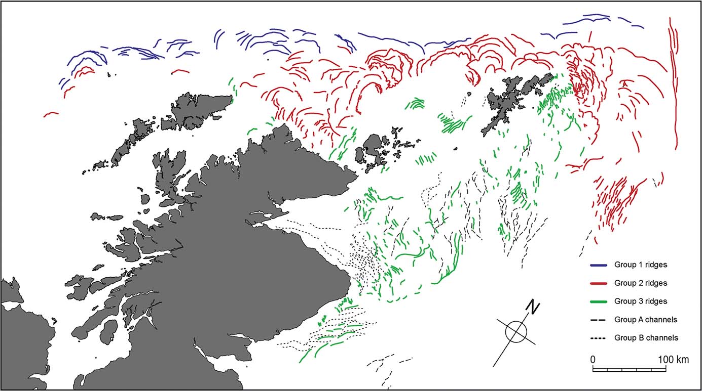
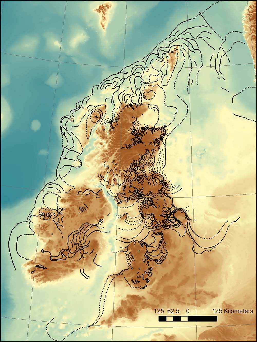
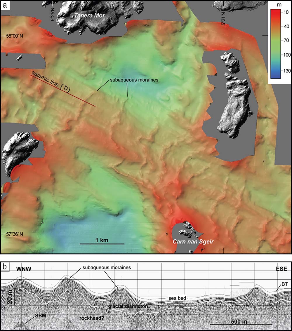
Submarine moraine banks recording former ice margin positions on the Atlantic Shelf were first mapped by Selby (Reference Selby1989), Stoker & Holmes (Reference Stoker and Holmes1991) and Stoker et al. (Reference Stoker, Hitchen and Graham1993). Identification of the pattern of moraine banks on the Hebrides Shelf, the West Shetland Shelf and the northern NSB has been transformed by mapping based on the Olex bathymetric database (www.olex.no), which has been used to generate images of seabed relief (Fig. 10). Ridges evident from Olex-based imagery have been mapped by Bradwell et al. (Reference Bradwell, Stoker, Golledge, Wilson, Merritt, Long, Everest, Hestvik, Stevenson, Hubbard, Finlayson and Mathers2008b) and Clark et al. (Reference Clark, Hughes, Greenwood, Jordan and Sejrup2012), both of whom interpreted these features as ice-marginal moraines (or moraine banks) deposited by grounded ice. These ridges often exceed 1 km in width, suggesting that they represent the prolonged deposition and glacitectonic deformation of sediment at oscillating grounding-line margins. The maps produced by Bradwell et al. (Reference Bradwell, Stoker, Golledge, Wilson, Merritt, Long, Everest, Hestvik, Stevenson, Hubbard, Finlayson and Mathers2008b; Fig. 11) and Clark et al. (Reference Clark, Hughes, Greenwood, Jordan and Sejrup2012) differ only in detail.
Merged onshore-offshore (topographic-bathymetric) surface model depicting the relief of Scotland north of the Southern Uplands and the adjacent continental shelf. Offshore data are derived from the Olex database (www.olex.no) and onshore relief from the NEXTMap Britain digital surface model (Intermap Technologies). Reproduced from Bradwell et al. (Reference Bradwell, Stoker, Golledge, Wilson, Merritt, Long, Everest, Hestvik, Stevenson, Hubbard, Finlayson and Mathers2008b) Earth-Science Reviews 88, 207–226. © 2008 NERC. Reproduced with permission from Elsevier B.V.

The outermost ridges (‘Group 1 ridges' in Fig. 11) are broadly arcuate features at or near the shelf edge. These are typically 2–10 km wide and up to 60 km long, and were interpreted by both Bradwell et al. (Reference Bradwell, Stoker, Golledge, Wilson, Merritt, Long, Everest, Hestvik, Stevenson, Hubbard, Finlayson and Mathers2008b) and Clark et al. (Reference Clark, Hughes, Greenwood, Jordan and Sejrup2012) as demonstrating the extension of the SIS to the shelf break (Fig. 9). Farther south, the Olex database is incomplete, but using the multibeam swath bathymetric data of the Irish National Seabed Survey, Dunlop et al. (Reference Dunlop, Shannon, McCabe, Quinn and Doyle2010) mapped moraines deposited by westward-moving ice from Scotland on the Malin Shelf east of the BDF between 55.5°N and 56.3°N. Here, the outermost ridge runs approximately parallel to the shelf edge, which exhibits furrows attributed to iceberg scour, suggesting that the grounded ice margin became marine-based as a result of advance into deep water, or as a consequence of sea-level rise.
Seafloor landforms on the Atlantic shelf and northern North Sea Basin mapped by Bradwell et al. (Reference Bradwell, Stoker, Golledge, Wilson, Merritt, Long, Everest, Hestvik, Stevenson, Hubbard, Finlayson and Mathers2008b) from the bathymetric data in Figure 10. Solid lines: ridges (moraines or moraine banks). Dashed lines: channels, interpreted as tunnel valleys excavated by subglacial meltwater. Reproduced from Bradwell et al. (Reference Bradwell, Stoker, Golledge, Wilson, Merritt, Long, Everest, Hestvik, Stevenson, Hubbard, Finlayson and Mathers2008b) Earth-Science Reviews 88, 207–226. © 2008 NERC. Reproduced with permission from Elsevier B.V.

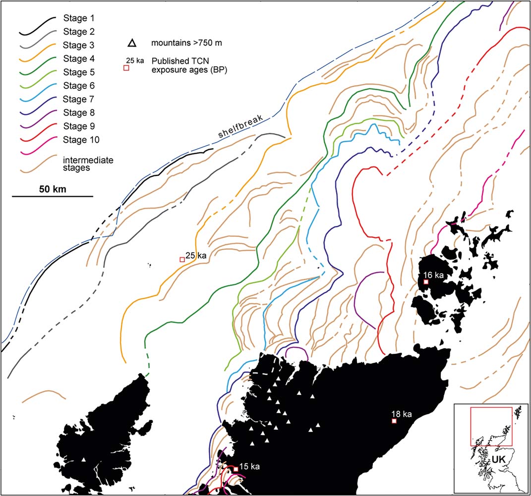
Although similar shelf-edge moraines W of Ireland have been shown to represent the limit of the last BIIS (Peters et al. Reference Peters, Benetti, Dunlop and Ó Cofaigh2015; Ballantyne & Ó Cofaigh Reference Ballantyne, Ó Cofaigh, Coxon, McCarron and Mitchell2017), there is persuasive evidence that those on the edge of the northern Hebrides Shelf were deposited by an earlier, pre-MIS3/2 ice sheet (Stoker et al. Reference Stoker, Hitchen and Graham1993, Reference Stoker, Leslie, Scott, Briden, Hine, Harland, Wilkinson, Evans and Ardus1994; Stoker Reference Stoker1995, Reference Stoker, Hitchen, Johnson and Gatliff2013). Seismostratigraphic research by Stoker & Holmes (Reference Stoker and Holmes1991) demonstrated that the shelf-edge moraines in this sector pre-date similar moraines on the West Shetland Shelf, being separated by an angular stratigraphic discordance. Though the time interval represented by this discordance is unknown, they postulated that that the two sets of moraines were deposited during two different glaciations. This conclusion has been supported by amino-acid diagenesis, which indicated that the moraines on the outer Hebrides Shelf pre-date MIS 3 (Stoker & Holmes Reference Stoker and Holmes1991; Stoker Reference Stoker, Hitchen, Johnson and Gatliff2013; Stoker & Bradwell Reference Stoker and Bradwell2005). Recent reappraisal of the pattern of moraine systems on the northern and central Hebrides Shelf by Bradwell & Stoker (Reference Bradwell and Stoker2015a) conforms to the stratigraphic evidence, and suggests that ice moving westward from the Outer Hebrides during the LLGM extended no farther than mid-shelf (Fig. 12). This interpretation is supported by research on the St Kilda archipelago, 65 km W of the Outer Hebrides and 40–60 km E of the shelf break, which has demonstrated that the last ice sheet failed to encroach on these islands (Sutherland et al. Reference Sutherland1984; Hiemstra et al. Reference Hiemstra, Shakesby and Vieli2015; Ballantyne et al. Reference Ballantyne, Fabel, Gheorghiu, Rodés, Shanks and Xu2017). Collectively, the evidence outlined above conflicts with the simple ‘shelf-edge' configuration of the last ice sheet promoted by Bradwell et al. (Reference Bradwell, Stoker, Golledge, Wilson, Merritt, Long, Everest, Hestvik, Stevenson, Hubbard, Finlayson and Mathers2008b) and Clark et al. (Reference Clark, Hughes, Greenwood, Jordan and Sejrup2012). The actual extent of the last ice sheet on the northern Hebrides shelf remains uncertain. It has been depicted as a broad arc extending west of the Outer Hebrides but terminating just east of St Kilda (Selby Reference Selby1989; Stoker et al. Reference Stoker, Hitchen and Graham1993). Bradwell & Stoker (Reference Bradwell and Stoker2015a, p. 317) suggested that the LLGM ice margin was “… situated close to the present-day coastline in NW Lewis…”, although this interpretation is based solely on the interpretation of submarine moraine configuration from bathymetric imagery. Conversely, the TCN ages obtained for North Rona (28.7±1.4 ka; Everest et al. Reference Everest, Bradwell, Stoker and Dewey2013) and a radiocarbon age of 22.5±0.3 14C ka BP (27.2–25.9 cal 14C ka) reported by Peacock et al. (Reference Peacock, Austin, Selby, Graham, Harland and Wilkinson1992) for a bivalve from glacimarine sediments west of moraine banks south of St Kilda suggest the extension of Outer Hebrides ice to at least mid-shelf.
Reconstructed ice-margin positions around northern Scotland (coloured lines), interpreted from the alignment of submarine moraines by Bradwell & Stoker (Reference Bradwell and Stoker2015a). Stages 1 and 2 are inferred to represent pre-MIS 3/2 moraines, and Stage 3 moraines are interpreted as the outermost Late Devensian moraines. Their interpretation of subsequent ice-sheet retreat (stages 4–10) implies early deglaciation of the northern Outer Hebrides and persistence of an ice cap centred on Orkney and Shetland after retreat of the ice margin to the present coast of NW Scotland. The dates depicted are selected (unrecalibrated) TCN ages. Reproduced from Bradwell, T. & Stoker, M. S. (Reference Bradwell and Stoker2015) Earth and Environmental Science Transactions of the Royal Society of Edinburgh 105, 297–322 with permission.

The evidence outlined above contravenes the widespread belief that there is “…unequivocal evidence for glaciation to the continental shelf edge all the way from SW Ireland to the Shetland Isles” (Clark et al. Reference Clark, Hughes, Greenwood, Jordan and Sejrup2012, p. 141), a proposition widely accepted in most recent accounts (Hubbard et al. Reference Hubbard, Bradwell, Golledge, Hall, Patton, Sugden, Cooper and Stoker2009; Chiverrell & Thomas Reference Chiverrell and Thomas2010; Gibbard & Clark Reference Gibbard and Clark2011; Hughes et al. Reference Hughes, Clark and Jordan2014, Reference Hughes, Gyllencreutz, Lohne, Mangerud and Svendsen2016). It demonstrates that westward advance of the last ice sheet was not halted by increasing water depth in all sectors. On the West Shetland Shelf, however, the mapped shelf-edge moraines are associated with stratigraphic units of inferred Late Devensian age (Stoker & Holmes Reference Stoker and Holmes1991; Bradwell & Stoker Reference Bradwell and Stoker2015a; Fig. 12), implying that ice moving NW across the shelf in this area terminated at the shelf break.
3.6. Ice sheet expansion: synthesis
The evidence summarised above indicates that marine-terminating ice existed in Scotland for several millennia prior to the growth of the last SIS, and that ice expansion across low ground and the adjacent shelf commenced within the period 35–32 ka. To the south, the expanding ice sheet initially invaded Ireland, the ISB and northern England, before the establishment of an ice divide across the North Channel limited southward ice flow. A N–S ice divide developed between the SW Highlands and N England, producing dominantly westerly ice flow toward the Malin Shelf and easterly flow towards the NSB. Ice from eastern Scotland was confluent with the FIS in the NSB, but there is debate as to whether this ultimately resulted in a confluent flow of ice towards the NW or the establishment of a (migratory) ice shed between NE Scotland and Norway that resulted in a northwesterly flow of ice from the Moray Firth and the NSB across Caithness and Orkney. Both Shetland and the Outer Hebrides probably developed independent ice caps that persisted as centres of ice dispersal throughout the expansion of the SIS. Glacigenic sedimentation on shelf-edge fans, the seismostratigraphy of the outer shelf, and the alignment of submarine moraine banks collectively suggest that the last SIS probably extended to the Atlantic shelf edge in most sectors, but no farther than mid-shelf on the Hebrides Shelf.
Assumption of ice-sheet expansion from the Scottish mainland after ∼34 ka, as suggested by the terrestrial dating evidence, implies that growth of the SIS to its maximum extent on the Atlantic shelf occurred over 4000–7000 years. Irrespective of the exact timing of the LLGM in this sector, the northern parts of the SIS appear to have reached their maximum extent prior to the global LGM of ∼26.5–19 ka (P. U. Clark et al. Reference Clark, McCabe, Schnabel, Clark, Freeman, Maden and Xu2009), probably reflecting the relatively small size of the SIS and its position adjacent to the Atlantic Ocean, which was a source of moisture-bearing airmasses that fed rapid ice-sheet growth so that ice centres responded rapidly to climate deterioration (Hughes et al. Reference Hughes, Gyllencreutz, Lohne, Mangerud and Svendsen2016; Patton et al. Reference Patton, Hubbard, Andreassen, Winsbarrow and Stroeven2016).
4. Trimlines, blockfields and the vertical dimension of the last ice sheet
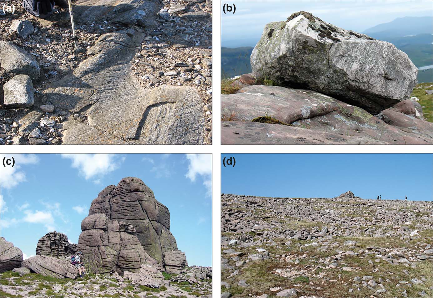
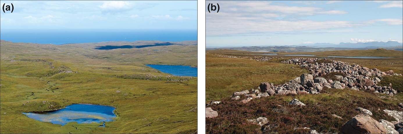
Two conflicting forms of evidence have informed interpretation of the vertical extent of the last ice sheet. Ice-moulded bedrock, striae, erratics and perched boulders occur on some mountain summits, implying over-running by wet-based glacier ice (Fig. 13a, b). Conversely, others are mantled by periglacial blockfields, sometimes interrupted by tors and outcrops of shattered rock (Fig. 13c, d). The contrast between blockfields on summits and ice-scoured bedrock on lower slopes in NW Scotland was initially interpreted as representing the upper limit of the SIS, implying that some summits remained above the ice sheet as nunataks (J. Geikie Reference Geikie1878, Reference Geikie1894; Godard Reference Godard1965). The restricted ice sheet model proposed by Bowen et al. (Reference Bowen, Rose, McCabe and Sutherland1986) favoured this view, and stimulated mapping across NW Scotland of trimlines marking the altitudinal boundary between ice-scoured terrain and blockfields. In Sutherland, for example, mapped trimlines descend northwestward from ∼850 m to ∼600 m near the coast (McCarroll et al. 1995); and across Wester Ross they descend northwestward from >900 m near the watershed to ∼700 m near the coast (Ballantyne et al. Reference Ballantyne, McCarroll, Nesje and Dahl1997).
(a) Striae on ice-moulded bedrock at 997 m altitude on Ben Challum, southern Grampians. (b) Quartzite erratic resting on ice-moulded sandstone bedrock at 860 m altitude on Beinn Damh, Wester Ross. (c) Granite tors rising above blockfield debris at the summit of Beinn Mheadhoin (1182 m), Cairngorm Mountains. (d) Periglacial blockfield of sandstone boulders at the summit (933 m) of Maol Cheann-dearg, Torridon. Quartzite erratics on the blockfield have produced cosmogenic 10Be exposure ages of ∼16 ka (Fabel et al. Reference Fabel, Ballantyne and Xu2012), indicating that they were deposited by the last ice sheet.

Ballantyne et al. (Reference Ballantyne, McCarroll, Nesje, Dahl and Stone1998a, Reference Ballantyne, McCarroll, Nesje, Dahl, Stone and Fifieldb) noted that the trimlines in NW Scotland could represent either an englacial thermal boundary within the SIS, with cold-based ice on high ground remaining frozen to the underlying substrate, or the upper limit of the SIS, and they favoured the latter interpretation. TCN ages for bedrock samples from mountains in Wester Ross, Skye, Harris and Caithness confirmed that whereas below-trimline samples returned ages consistent with the timing of deglaciation, above-trimline samples yielded pre-LLGM ages (Fig. 14). Samples from two erratic boulders resting on a blockfield in Wester Ross gave TCN ages of >55 ka (Stone et al. Reference Stone, Ballantyne and Fifield1998), suggesting that the erratics were deposited by an earlier, thicker ice sheet.
Mapping of trimline altitudes in Caithness, however, showed that that these were inconsistent with TCN ages indicating that Orkney was completely overrun by the last ice sheet (Ballantyne & Hall Reference Ballantyne and Hall2008), causing the reinterpretation of Scottish trimlines as thermal boundaries marking the upper limit of erosion by wet-based ice within a much thicker SIS (Kleman & Glasser Reference Kleman and Glasser2007; Ballantyne Reference Ballantyne2010; Kuchar et al. Reference Kuchar, Milne, Hubbard, Patton, Bradley, Shennan and Edwards2012). This reinterpretation is supported by numerical models of the BIIS, which indicate persistent cold-based ice over mountain summits (Boulton & Hagdorn Reference Boulton and Hagdorn2006; Hubbard et al. Reference Hubbard, Bradwell, Golledge, Hall, Patton, Sugden, Cooper and Stoker2009) and by evidence of glacial modification of tors on the Cairngorm Mountains (Hall & Phillips Reference Hall and Phillips2006). Over-riding of blockfield-mantled summits in NW Scotland by the SIS was tested by Fabel et al. (Reference Fabel, Ballantyne and Xu2012), who obtained TCN ages for 14 erratic boulders resting on summit blockfields. Nine of these yielded post-LLGM (recalibrated) ages of 17.5±1.0 ka to 14.9±1.5 ka (Fig. 14), demonstrating that the last ice sheet must have overtopped all summits in this area. TCN dating of glacially-deposited boulders on a summit blockfield in southern Ireland confirmed this interpretation (Ballantyne & Stone Reference Ballantyne and Stone2015), suggesting that all summit blockfields in the British Isles represent periglacial regolith that was preserved under cold-based ice during the LGM (Hopkinson & Ballantyne Reference Hopkinson and Ballantyne2014).
TCN exposure ages obtained for high-level erratics and bedrock samples above and below trimlines in the Scottish Highlands. The shaded area represents the timing of the LGM (26.5–19.0 ka). Horizontal bars represent ±1σ uncertainties. Post-LGM exposure ages obtained for most high-level erratics demonstrate that mountain summits were over-run by the last ice sheet. Reproduced from Fabel et al. (Reference Fabel, Ballantyne and Xu2012) Quaternary Science Reviews 55, 91–102. Reproduced with permission from Elsevier. © 2012 Elsevier B.V.

Over-running of all mountain summits by the SIS means that the maximum altitude of the ice sheet cannot be deduced directly from field evidence. An early model of the BIIS based on the assumption of a uniform basal shear stress of 100 kPa suggested that the SIS had a maximum altitude (relative to present sea level) of 1800–1900 m across much of the Highlands and Southern Uplands (Boulton et al. Reference Boulton, Jones, Clayton, Kenning and Shotton1977). Later models based on inferred glacio-isostatic depression have indicated maximum ice-surface altitudes of 1000–2500 m, with more recent models favouring thicker ice cover (Lambeck Reference Lambeck1995; Shennan et al. Reference Shennan, Peltier, Drummond and Horton2002; Kuchar et al. Reference Kuchar, Milne, Hubbard, Patton, Bradley, Shennan and Edwards2012), and Hughes et al. (Reference Hughes, Clark and Jordan2014) calculated that the altitude of the ice divide over northern Scotland must have exceeded ∼1400 m. The climate-proxy-driven, thermomechanically-coupled models of Boulton & Hagdorn (Reference Boulton and Hagdorn2006) indicate maximum ice altitudes of ∼1500 m to ∼2250 m across the Central Grampians. Subsequent numerical modelling, however, suggests that the SIS experienced ‘binge-and-purge' behaviour, whereby the cold-based upland core was periodically drawn down by fast-flowing ice streams (Hubbard et al. Reference Hubbard, Bradwell, Golledge, Hall, Patton, Sugden, Cooper and Stoker2009; see below). Such behaviour implies that rather than building to a maximum altitude then declining, the thickness of the SIS fluctuated, and that the maximum altitude of the ice sheet varied both spatially and temporally.
5. Ice streams and ice-sheet models
5.1. Palaeo-ice streams of the last Scottish Ice Sheet
Ice streams are corridors of fast-flowing ice within ice sheets (Bentley Reference Bentley1987; Bennett Reference Bennett2003; Truffer & Echelmeyer Reference Truffer and Echelmeyer2003; Benn & Evans Reference Benn and Evans2010; Rignot et al. Reference Rignot, Mouginot and Scheuchl2011). Velocities reach several hundreds of metres per year, often over deforming sediments, and their margins are defined by shear zones. Palaeo-ice streams that developed within former ice sheets can be identified by a range of criteria, notably a convergent flow pattern, a distinct flow track with sharply defined lateral margins, markedly elongate bedforms and lineations, and terminal sediment accumulations, often in the form of trough-mouth fans (Stokes & Clark Reference Stokes and Clark1999, Reference Stokes and Clark2001).
On the basis of such evidence, four eastward-flowing ice streams that drained the SIS have been identified; all exhibit topographic control and extended into the NSB. The Tyne Ice Stream drained ice from the Southern Uplands, Cheviots, Lake District and northern Pennines (Fig. 7). During the LLGM, flow was W–E, but a subsequent shift to southeasterly flow reflects the increased dominance of Scottish ice (Livingstone et al. Reference Livingstone, Ó Cofaigh and Evans2008, Reference Livingstone, Ó Cofaigh and Evans2010b, Reference Livingstone, Evans, Ó Cofaigh, Davies, Merritt, Huddart, Mitchell, Roberts and Yorke2012, Reference Livingstone, Roberts, Davies, Evans, Ó Cofaigh and Gheorghiu2015). The ∼20 km-wide Tweed Ice Stream, reconstructed by Everest et al. (Reference Everest, Bradwell and Golledge2005) from the distribution and orientation of drumlins, megadrumlins and megaflutes, flowed NE to E between the Lammermuir and Cheviot Hills, draining an area of ∼3500 km2 and extending ∼65 km to the present coastline. The Strathmore Ice Stream flowed eastward in a ∼45 km-wide corridor between the Highland edge and NE Fife, is defined by streamlined bedrock and bedforms, and exhibits evidence of a post-LLGM northeastward shift in flow (Golledge & Stoker Reference Golledge and Stoker2006). Farther north, there is evidence of eastward streaming of ice in the Moray Firth, although changes in the offshore configuration of the Moray Firth Ice Stream remain to be worked out in detail (Merritt et al. Reference Merritt, Auton and Firth1995, Reference Merritt, Auton, Connell, Hall and Peacock2003, Reference Merritt, Connell and Hall2017; Graham et al. Reference Graham, Lonergan and Stoker2009). In the NSB, the NW–SE-trending MSGLs identified by Graham et al. (Reference Graham, Lonergan and Stoker2007, Reference Graham, Lonergan and Stoker2010, Reference Graham, Stoker, Lonergan, Bradwell, Stewart, Ehlers, Gibbard and Hughes2011), crossing the Witch Ground Basin (see section 3.4.4), have been interpreted as representing development of a former ice stream, although there is debate as to whether this represents former ice streaming NW towards the Orkney–Shetland channel (Fig. 9) or SE away from an ice divide over the northern NSB (Sejrup et al. Reference Sejrup, Clark and Hjelstuen2016). Hall & Glasser (2003) used the term ‘ice stream' to describe the effects of wet-based sliding ice in Glen Avon (Cairngorms), but whether true ice streams developed in the Cairngorm troughs is questionable.
In the western NSB, the coalescence of ice emanating from the Forth, the Tweed and probably the eastern Grampians (Davies et al. Reference Davies, Roberts, Bridgland, Ó Cofaigh and Riding2011) fed the North Sea Lobe (NSL), a major ice stream that moved southwards along eastern England, reaching the Norfolk coast. Livingstone et al. (Reference Livingstone, Evans, Ó Cofaigh, Davies, Merritt, Huddart, Mitchell, Roberts and Yorke2012) suggested that the NSL was initially constrained by the FIS to the east, but persisted after a decoupling of the FIS and BIIS. Moss samples from beneath the lower of two tills (the Skipsea Till) at Dimlington on the Holderness coast of east Yorkshire produced radiocarbon ages of 22.9–21.9 cal 14C ka and 22.4–21.9 cal 14C ka (Penny et al. Reference Penny, Coope and Catt1969), and OSL dating indicates the deposition of the Skipsea Till at ∼21.6 ka (Bateman et al. Reference Bateman, Evans, Roberts, Medialdea, Ely and Clark2017), implying that the NSL reached its maximum extent several millennia after the LLGM on the Atlantic shelf. At Dimlington, laminated silts and cross-bedded sands separate the Skipsea Till from an upper till, the Withernsea Till. OSL and radiocarbon ages suggest that the latter was deposited by a readvance that culminated at ∼16.8 ka, although as Bateman et al. (Reference Bateman, Buckland, Whyte, Ashurst, Boulter and Panagiotakopulu2011, Reference Bateman, Evans, Roberts, Medialdea, Ely and Clark2017) acknowledged, this timing appears contrary to wider evidence for advanced deglaciation by this time.
To the south, ice from Galloway joined that from England, Wales and Ireland to feed the Irish Sea Ice Stream (ISIS), which drained >17 % of the BIIS. The southern limit of this ice stream has been placed near the edge of the Celtic Sea Shelf (Praeg et al. Reference Praeg, McCarron, Dove, Ó Cofaigh, Scott, Monteys, Facchin, Romeo and Coxon2015), implying a maximum travel distance exceeding 800 km. To the west, several authors have depicted a Hebrides Ice Stream that was confluent with a North Channel–Malin Shelf Ice Stream fed by ice from northern Ireland (Dunlop et al. Reference Dunlop, Shannon, McCabe, Quinn and Doyle2010) and SW Scotland (Finlayson et al. Reference Finlayson, Fabel, Bradwell and Sugden2014), and probably terminated at the shelf break, feeding sediment to the BDF (Fig. 9). Bedform evidence from the main flow track of this postulated ice stream is lacking, but Howe et al. (Reference Howe, Dove, Bradwell and Gafeira2012) and Dove et al. (Reference Dove, Arosio, Finlayson, Bradwell and Howe2015) have shown that elongate streamlined bedforms cut southwestward across structural trends on the seafloor of the Sea of the Hebrides. They interpreted these as representing the onset zone of the Hebrides Ice Stream, where ice accelerated from an area dominated by bedrock obstacles onto the sediment-dominated shelf. Streamlined bedforms in western Kintyre probably represent associated westward ice streaming from the Firth of Clyde, and Finlayson et al. (Reference Finlayson, Fabel, Bradwell and Sugden2014) have suggested that the resulting drawdown of ice resulted in a ∼60 km westward shift of the N–S ice divide across central Scotland. Whether the landform evidence in the Sea of the Hebrides relates to an ice stream at the LLGM or during overall retreat (as suggested by cross-cutting flow indicators) is uncertain (Dove et al. Reference Dove, Arosio, Finlayson, Bradwell and Howe2015).
The most intensively researched Scottish palaeo-ice stream is the Minch Ice Stream, first identified by Stoker & Bradwell (Reference Stoker and Bradwell2005). During the LLGM, it drained an area of 10,000–15,000 km2 and was fed by ice from the NW Highlands, Skye and eastern Lewis, which converged in the North Minch and followed a ∼200 km-long, 40–50 km-wide trough that terminates at the SSF (Fig. 15). Bradwell et al. (Reference Bradwell, Stoker and Larter2007) identified at least nine land-based onset zones characterised by streamlined landforms. Spectacular bedrock megagrooves formed by subglacial abrasion and meltwater erosion occur in a 20 km-wide corridor north of Loch Broom (Bradwell et al. Reference Bradwell, Stoker and Krabbendam2008c), but probably reflect erosion over several glacial cycles. In the onset zone around Loch Laxford, Bradwell (Reference Bradwell2013) showed that the zone of accelerated ice flow can be identified from the distribution of bedrock landforms such as roches moutonnées, whalebacks and plucked rock faces. Within the North Minch, the signature of former ice streaming includes an assemblage of ‘hard bed' subglacial forms, including large submarine crag-and-tail features, bedrock megaflutes and megagrooves, as well as drumlinoid bedforms in areas of sediment cover (Bradwell & Stoker Reference Bradwell and Stoker2015b). Farther N, the ice stream followed the trough that terminates at the SSF, though it is uncertain whether grounded ice reached the shelf edge or terminated on mid-shelf (Bradwell & Stoker Reference Bradwell and Stoker2015a), possibly with a floating ice shelf extending to the shelf break. Fluctuations in the size and velocity of the ice stream may have resulted in the periodic drawdown of ice in source areas, causing shifts in the location of the main N–S ice divide across the NW Highlands (Bradwell et al. Reference Bradwell, Stoker and Larter2007). Eastward migration of this divide probably explains the eastwards and westwards transport of erratics across the Moine Thrust Zone (Lawson Reference Lawson1990) and from an augen-gneiss outcrop ∼15 km E of the present watershed (Sutherland Reference Sutherland1984). This interpretation is also consistent with the easterly migration of the ice-divide inferred by Hughes et al. (Reference Hughes, Clark and Jordan2014; Fig. 5).
Main palaeoglaciological features of the Minch Ice Stream. White lines indicate proposed ice-stream tributaries and flowlines. Thick lines are inferred terminus positions proposed by Bradwell & Stoker (Reference Bradwell and Stoker2015a), who considered that the outermost line probably represents a pre-MIS3/2 ice limit, but the inner lines represent Late Devensian ice margin positions. Hatching indicates an area of subglacial bedforms and iceberg scours, but lacking moraines. From Bradwell & Stoker (Reference Bradwell and Stoker2015b) Boreas 44, 255–276. © Boreas Collegium. Reproduced with permission from John Wiley & Sons Ltd.

5.2. Ice-sheet models
Although the evidence for major ice streams draining the SIS is compelling, the history of most ice streams is poorly constrained. In their reconstruction of ice-sheet evolution, Hughes et al. (Reference Hughes, Clark and Jordan2014) envisaged initial development of a thick integrated ice sheet, with ice-stream development contributing to subsequent thinning and ice-divide migration during and after the ice sheet achieved its maximum extent, but did not preclude ice-stream formation during ice-sheet expansion. The first numerical simulation experiments driven by proxy climate functions (Boulton & Hagdorn Reference Boulton and Hagdorn2006) indicated the early development of ice streams draining the predominantly cold-based upland core of the SIS, with the resultant drawdown of the ice-sheet surface. Their models also identified major ice discharge arteries at the locations of the Minch, Hebrides, Irish Sea and Moray Firth Ice Streams.
Later thermomechanically-coupled models of the BIIS driven by a scaled NGRIP oxygen isotope curve for the period 38–10 ka (Hubbard et al. Reference Hubbard, Bradwell, Golledge, Hall, Patton, Sugden, Cooper and Stoker2009) have indicated a more detailed scenario. A key finding of the optimal (most geologically-consistent) model is that it retrodicts major ‘binge and purge' cycles during the lifetime of the ice sheet, identifying prolonged phases of build-up of cold-based, high-viscosity ice succeeded by ‘purge' phases triggered by abrupt warming. Such ‘purge' phases are characterised by the widespread development of ice streams around the cold-based core of the modelled ice sheet. At such times, the ice sheet surface is drawn down but the ice margins advance. The optimal model generates transient but recurrent ice streaming at all the Scottish ice-stream locations described above, and also intervening areas of fast-flowing ice that may have captured ice flow from the known ice-stream locations. It retrodicts limited ice cover (mainly over the Highlands, with tidewater-terminating margins) prior to ∼33 ka, followed by extension of the ice margin to (or near to) the Atlantic Shelf edge at ∼29 ka during the first major ‘purge' event, immediately followed by the development of all the Scottish ice streams identified from the geomorphological evidence. It also suggests, however, that small ice streams may have developed during ice-sheet build-up. More generally, this model suggests that although the largest ice streams (the Hebrides and Irish Sea Ice Streams) were active throughout much of the last glacial cycle, smaller ice streams were only intermittently active over centennial timescales.
A notable feature of the optimum model of Hubbard et al. (Reference Hubbard, Bradwell, Golledge, Hall, Patton, Sugden, Cooper and Stoker2009) is that it suggests that the initial advance of the SIS to the Atlantic Shelf edge, deep into England and Ireland and far out into the NSB at ∼29 ka was followed first by shrinkage to a much smaller ice mass centred on the Scottish Highlands by ∼27 ka, then by climate-driven re-expansion to form an even more extensive ice sheet by ∼23.7 ka. There appears to be no evidence to support drastic shrinkage of the SIS between 29 ka and 27 ka (many authors have inferred that ∼27 ka approximates the timing of the SIS maximum) but this may be because of ‘erosion censoring': later, more extensive ice advances obscure or obliterate the geomorphological evidence produced by earlier less extensive events (Kirkbride & Winkler Reference Kirkbride and Winkler2012). The same caveat applies to moraine sequences on offshore shelves: nested ice-marginal moraines represent ice extent at particular times, but intervening events involving less extensive ice cover are likely to be absent from the landform record. There may therefore be a prolonged temporal hiatus between one set of moraines and the next, during which the ice margin may have retreated and readvanced on several occasions. Thus although ‘outer' moraines are older than ‘inner' moraines, the intervening time period may have involved complex changes in ice extent or flow direction.
Below we outline the results of attempts to reconstruct the deglaciation history of the SIS at ice-sheet scale, before considering the detailed evidence for particular sectors. Apart from the numerical modelling by Hubbard et al. (Reference Hubbard, Bradwell, Golledge, Hall, Patton, Sugden, Cooper and Stoker2009), the former are based on the pattern of offshore landforms, terrestrial flowsets and a patchy distribution of radiocarbon and TCN ages, some of questionable validity. Not all reconstructions are adequately integrated with the stratigraphic record. At the time of writing, a major initiative (the BRITICE-CHRONO project), designed to refine the chronology of BIIS retreat, is nearing completion, and promises to yield new insights into the retreat behaviour of the SIS (www.britice-chrono.group.shef.ac.uk).
6. Deglaciation at ice-sheet scale
The earliest reconstruction of the pattern of SIS retreat (Bradwell et al. Reference Bradwell, Stoker, Golledge, Wilson, Merritt, Long, Everest, Hestvik, Stevenson, Hubbard, Finlayson and Mathers2008b) was largely based on the mapping of moraine banks, moraines and tunnel valleys (excavated by subglacial meltwater) from Olex bathymetric data (Fig. 10). From the location of the outermost moraines (‘Group 1' in Fig. 11) they placed the ice margin at the shelf edge at 30–25 ka (Fig. 9). The large lobate, bifurcating and overprinting moraines of their ‘Group 2' set they attributed to oscillation of grounded but calving margins and changes in flow direction, possibly related to rising sea level, with localised De Geer moraines indicating grounded tidewater margins. The smaller moraines of Group 3 (Fig. 11) and associated meltwater channels are interpreted as marking a more stable phase of deglaciation (∼24–18 ka) following decoupling of the SIS from the FIS. From these patterns, and from bathymetric data, they argued that initial decoupling took the form of development of a elongate marine embayment that extended southward from the shelf edge E of Shetland to the Witch Ground Basin by ∼24 ka as sea level rose.
The numerical model of Hubbard et al. (Reference Hubbard, Bradwell, Golledge, Hall, Patton, Sugden, Cooper and Stoker2009) differs in suggesting that widespread retreat then readvance of the ice margin occurred between ∼29 ka and ∼24 ka, with subsequent extensive ice cover until ∼19.4 ka, after which it suggests thinning and retreat of all sectors in response to sustained warmer conditions. During the period ∼19.4–17.4 ka, the model indicates dynamic ice-stream activity, with switching and competition across core areas and numerous localised, short-lived readvances of the ice margin, but persistence of ice cover across the present land area of Scotland. It suggests that after ∼17.2 ka, ice was largely confined to Scotland, but with substantial advances reaching northern Ireland, renewed ice-stream activity and possible surging into the NSB. By ∼15.7–15.6 ka, it suggests a break-up of the residual SIS into a substantial ice cap over the Highlands and small ice caps over the Southern Uplands, Outer Hebrides, Orkney and Shetland.
The empirical reconstruction of Clark et al. (Reference Clark, Hughes, Greenwood, Jordan and Sejrup2012) was based on the terrestrial landform record of the BRITICE database (C.D. Clark et al. Reference Clark, McCabe, Mix and Weaver2004; Evans et al. Reference Evans, Clark and Mitchell2005; subsequently updated by Clark et al. Reference Clark, Ely, Greenwood, Hughes, Meehan, Barr, Bateman, Bradwell, Doole, Evans, Jordan, Monteys, Pellicer and Sheehy2017), the subglacial bedform record of Hughes et al. (Reference Hughes, Clark and Jordan2010), independent interpretation of offshore bathymetric data, and compilation of all published ages constraining the timing of ice-margin retreat (Hughes et al. Reference Hughes, Greenwood and Clark2011). This information was interpreted as a retreat pattern for the entire BIIS (Fig. 16), although Clark et al. (Reference Clark, Hughes, Greenwood, Jordan and Sejrup2012) acknowledged the uncertainties associated with matching up fragmentary landform evidence. Like Bradwell et al. (Reference Bradwell, Stoker, Golledge, Wilson, Merritt, Long, Everest, Hestvik, Stevenson, Hubbard, Finlayson and Mathers2008b), the starting point for their reconstruction was an ice sheet terminating at the Atlantic shelf edge at ∼27 ka, although as noted in section 3.5 it now seems unlikely that the SIS reached the shelf edge in all sectors. Clark et al. (Reference Clark, Hughes, Greenwood, Jordan and Sejrup2012), and updated reconstructions based on similar data (Hughes et al. Reference Hughes, Clark and Jordan2014, Reference Hughes, Gyllencreutz, Lohne, Mangerud and Svendsen2016), have outlined subsequent changes to ice-sheet configuration as a series of time slices. Their interpretations of the sequence of events affecting the Scottish Ice Sheet are summarised in Table 2.
Reconstruction of the pattern of retreat of the BIIS as depicted by Clark et al. (Reference Clark, Hughes, Greenwood, Jordan and Sejrup2012). Solid black lines record former ice margins based on landform evidence and dashed lines are interpolated or extrapolated ice margin positions. Reproduced from Clark et al. (Reference Clark, Hughes, Greenwood, Jordan and Sejrup2012) Quaternary Science Reviews 44, 112–146, with permission from Elsevier. © 2010 Elsevier Ltd.

Time-slice reconstruction of SIS deglaciation (Clark et al. Reference Clark, Hughes, Greenwood, Jordan and Sejrup2012; Hughes et al. Reference Hughes, Gyllencreutz, Lohne, Mangerud and Svendsen2016)

The reconstructions outlined above differ in detail and timing of events, but agree on the general sequence, with the exception of the retreat phase at ∼27 ka modelled by Hubbard et al. (Reference Hubbard, Bradwell, Golledge, Hall, Patton, Sugden, Cooper and Stoker2009) and the interpretation of events in the NSB. There is agreement that retreat of ice on the Atlantic shelf was probably driven by sea-level rise, the development of calving margins and a prolonged period of dynamic reorganisation of the northern SIS, represented by the multiple, sometimes overlapping moraines W of Orkney and N and E of Shetland. The reconstructions also suggest that substantial thinning and retreat of the SIS occurred mainly after ∼22 ka, and particularly after ∼19 ka, but was a complex affair involving transient ice streaming, divide migration and development of a polycentric ice sheet that was largely confined to the Scottish mainland and adjacent inner shelves by 17–16 ka, with some residual satellite ice caps or icefields.
7. Regional deglaciation 1: the offshore shelves, Northern Isles and Outer Hebrides
7.1. The northern sector of the last Scottish Ice Sheet
Deglaciation of the northern Hebrides Shelf and West Shetland Shelf has been reconstructed by Bradwell & Stoker (Reference Bradwell and Stoker2015a), who employed the pattern of ice-marginal landforms mapped from high-resolution echo-sounder data and stratigraphic and sedimentological data (Stoker et al. Reference Stoker, Hitchen and Graham1993; Stoker & Varming Reference Stoker, Varming, Ritchie, Ziska, Johnson and Evans2011; Stoker Reference Stoker, Hitchen, Johnson and Gatliff2013) to identify stages in ice-margin retreat (Fig. 12). Intervening and nearshore sequences of small, sharp-crested ridges in various locations are interpreted as De Geer moraines, implying that the larger moraine banks represent grounded ice margins terminating in shallow water.
On stratigraphic grounds (see section 3.5 above), Bradwell & Stoker (Reference Bradwell and Stoker2015a) assigned the outermost moraines of their stages 1 and 2 (Fig. 12) to deposition by a pre-Late Devensian ice sheet, implying that the oldest moraines of Late Devensian age are represented by their stage 3 ice limit, depicted at the edge of the West Shetland Shelf but on mid-shelf farther SW. As North Rona, where ice retreat was originally dated to ∼25 ka (Everest et al. Reference Everest, Bradwell, Stoker and Dewey2013; recalibrated as ∼29 ka; section 3.5), lies outside this limit, this interpretation appears to imply that the last ice sheet locally extended beyond the mapped stage 3 limit but left no footprint, unless the stage 2 ice limit has been misattributed. Stage 4 implies subsequent recession of the ice margin along the entire sector and suggests early deglaciation of northernmost Lewis. If the suggested configuration of subsequent stages is correct, it implies: (1) very early deglaciation of Cape Wrath, possibly the first part of mainland Scotland to emerge from the ice sheet; (2) early deglaciation of the North Minch and probably parts of eastern Lewis; and (3) progressive decoupling of ice nourished in NW Scotland from an ice mass that covered NE Caithness, Orkney and Shetland. The configuration of this ice mass is less certain. Bradwell & Stoker (Reference Bradwell and Stoker2015a) suggested a correlation of their stage 9 limit W of Orkney with moraine banks SE of Orkney (Fig. 12), but this solution appears to imply southwards ice movement across the northern coast of Caithness and shrinkage of the ice margin towards a residual ice cap on Orkney. The terrestrial field evidence, however, suggests that the final ice movement across both Caithness and Orkney was SE–NW, with no reported evidence for a late-stage Orkney ice cap (Hall et al. 2011, 2016b; Hall & Riding 2016).
The published dating evidence for these events is slender. The inferred stage 3 ice limit must post-date the retreat of the ice margin from North Rona at 28.7±1.4 ka, and TCN dating of the Wester Ross Readvance places the ice margin across the fjords and peninsulas in the south of the area depicted in Figure 12 at 15.3±0.7 ka (see section 8.1 below). Samples from bedrock surfaces and boulders on low ground at sites on Orkney have, excluding outliers, produced five recalibrated 10Be exposure ages of 17.2±2.4 ka to 16.0±2.0 ka (Phillips et al. Reference Phillips, Hall, Ballantyne, Binnie, Kubik and Freeman2008), with a weighted mean age of 16.5±1.2 ka (Fig. 19), indicating that Orkney was largely ice-free by that time. Two samples from Dunnet Head on the N coast of Caithness have a mean age of 17.5±1.1 ka, suggesting deglaciation of the Pentland Firth prior to the final deglaciation of Orkney.
7.2. Shetland
As outlined earlier, there is persuasive (though contested) evidence that an independent ice cap persisted over Shetland throughout the last glacial cycle (Hall 2013). The pattern of offshore moraines is consistent with this interpretation (Figs 11, 16), indicating oscillatory retreat of an independent Shetland Ice Cap from the shelf edge and from near the edge of the Norwegian Channel. Bradwell et al. (Reference Bradwell, Stoker, Golledge, Wilson, Merritt, Long, Everest, Hestvik, Stevenson, Hubbard, Finlayson and Mathers2008b), Clark et al. (Reference Clark, Hughes, Greenwood, Jordan and Sejrup2012) and Hughes et al. (Reference Hughes, Clark and Jordan2014, Reference Hughes, Gyllencreutz, Lohne, Mangerud and Svendsen2016) all depict the ice margin progressively retreating towards Shetland and the eventual isolation of an ice cap over the archipelago. The TMC model of Hubbard et al. (Reference Hubbard, Bradwell, Golledge, Hall, Patton, Sugden, Cooper and Stoker2009) suggests separation of the Shetland Ice Cap before 17 ka. Radiocarbon dates from marine shells recovered from vibrocores indicate that Shetland ice retreated from the Viking Bank, ∼155 ENE of Shetland, before 18.3–17.3 cal 14C ka (Peacock Reference Peacock1995) and from a site ∼70 km E of Shetland before ∼15.1–14.1 cal 14C ka (Peacock & Long Reference Peacock and Long1994). Basal radiocarbon ages obtained from organic material at sites in southern Shetland indicate deglaciation prior to 15.4–15.2 cal 14C ka (Whittington et al. Reference Whittington, Buckland, Edwards, Greenwood, Hall and Robinson2003), 16.2–14.8 cal 14C ka (Birnie Reference Birnie2000) and 16.1–15.8 cal 14C ka (Hulme & Shirrifs 1994), although the last-mentioned inferred the onset of postglacial sedimentation as early as 16.9–16.6 ka. Collectively, the available dating evidence suggests that isolation of the Shetland Ice Cap occurred before 17 ka, and that much of Shetland was deglaciated between 17 ka and 16 ka.
7.3. The North Sea Basin (NSB)
Interpretation of the timing and nature of the decoupling of the SIS and FIS in the NSB has proved controversial. Forminifera and molluscs within stratified glacimarine or marine sediments overlying till (deformed marine sediments) in a core from the Witch Ground Basin (∼162 km NE of Rattray Head) have produced radiocarbon ages of 27.0–26.3, 25.3–24.2 to 23.8–23.0 cal 14C ka (Sejrup et al. Reference Sejrup, Haflidason, Aarseth, King, Forsberg, Long and Rokoengen1994). The oldest date suggests that the central NSB may have become deglaciated as early as ∼27 ka (Sejrup et al. Reference Sejrup, Haflidason, Aarseth, King, Forsberg, Long and Rokoengen1994, Reference Sejrup, Nygård, Hall and Haflidason2009, Reference Sejrup, Hjelstuen, Nygård, Haflidason and Mardal2015; Graham et al. Reference Graham, Lonergan and Stoker2010). Other samples in contexts indicating deglaciation of this area are, however, much younger (<22 cal 14C ka), suggesting a hiatus in the stratigraphic record (Sejrup et al. Reference Sejrup, Clark and Hjelstuen2016).
Bradwell et al. (Reference Bradwell, Stoker, Golledge, Wilson, Merritt, Long, Everest, Hestvik, Stevenson, Hubbard, Finlayson and Mathers2008b) suggested that the initial decoupling of the SIS and FIS followed a bathymetric depression that extends from the shelf edge N of Shetland southwards to the Witch Ground Basin. They argued that a calving margin propagated rapidly southward from the shelf edge, creating a marine embayment between the two ice sheets, an interpretation accepted by several authors (Graham et al. Reference Graham, Lonergan and Stoker2010; Sejrup et al. Reference Sejrup, Hjelstuen, Nygård, Haflidason and Mardal2015; Merritt et al. Reference Merritt, Connell and Hall2017). The reconstruction by Clark et al. (Reference Clark, Hughes, Greenwood, Jordan and Sejrup2012) offered two possible scenarios: (1) early (∼25 ka) and complete separation of the BIIS and FIS; and (2) partial decoupling of the SIS from the FIS by ∼23 ka along a marine embayment, a scenario similar to that proposed by Bradwell et al. (Reference Bradwell, Stoker, Golledge, Wilson, Merritt, Long, Everest, Hestvik, Stevenson, Hubbard, Finlayson and Mathers2008b). They noted, however, that the latter scenario requires persistence of a residual ice dome south of the proposed embayment, for which there is no evidence.
An alternative interpretation, proposed by Sejrup et al. (Reference Sejrup, Clark and Hjelstuen2016), is based on bathymetric landform evidence indicating that an initial westward extension of ice flowing NW along the Norwegian Channel (a broad bathymetric trough parallel to the coast of SW Norway) is overprinted by moraines indicating ice advance from a Shetland–Orkney ice centre. This evidence suggests that acceleration, thinning and retreat of the Norwegian Channel Ice Stream (NCIS) debuttressed the ice flowing from Shetland and Orkney, causing it to expand eastward (Fig. 17). Radiocarbon-dated records of glacigenic debris flows at the NCIS terminus demonstrate extremely high sediment flux at ∼20–19 ka (Nygård et al. Reference Nygård, Sejrup, Haflidason, Lekens, Clark and Bigg2007), which Sejrup et al. (Reference Sejrup, Clark and Hjelstuen2016) attributed to the onset of NCIS acceleration and thinning, and radiocarbon ages relating to its subsequent retreat suggest decoupling of the ice sheets in the eastern NSB at ∼18.5 ka, accompanied by drainage of a former ice-dammed lake in the southern NSB (Fig. 17). This interpretation places the line of disengagement of the BIIS and FIS farther east than previously depicted, suggesting that much of the ice occupying the NSB at the time of separation was of Scottish rather than Fennoscandian provenance. Sejrup et al. (Reference Sejrup, Clark and Hjelstuen2016) envisaged that decoupling of the two ice sheets led to a reorganisation of flow in the BIIS, accompanied by readvances, ice thinning and a rapid retreat of its eastern margins (Fig. 17). This interpretation is consistent with the persistence of a residual ice mass over Orkney and Shetland (Bradwell & Stoker Reference Bradwell and Stoker2015a) and does not require the existence of a remnant ice dome in the southern NSB, but conflicts with radiocarbon ages from the Witch Ground Basin and eastern Scotland that appear to imply much earlier deglaciation of these areas (McCabe et al. Reference McCabe, Clark, Smith and Dunlop2007; Sejrup et al. Reference Sejrup, Haflidason, Aarseth, King, Forsberg, Long and Rokoengen1994, Reference Sejrup, Nygård, Hall and Haflidason2009, Reference Sejrup, Hjelstuen, Nygård, Haflidason and Mardal2015).
Reconstructions of successive ice-sheet configurations in the North Sea Basin (NSB) proposed by Sejrup et al. (Reference Sejrup, Clark and Hjelstuen2016): (a) maximum configuration with an ice divide extending from NE Scotland to SW Norway and an ice-dammed lake in the southern NSB; (b) initiation of ice-sheet collapse: expansion and acceleration of the Norwegian Channel Ice Stream (NCIS) (dark blue lines) causes drawdown of ice and destroys the ice divide. Grounding line retreat in the Norwegian Channel progressively debuttresses ice on either side; (c) decoupling of the BIIS and FIS as the NCIS retreats, causing northward drainage of the ice-dammed lake. Red arrows indicate readvances of the BIIS; and black arrows indicate net westward retreat of the BIIS ice margin. Reproduced from Sejrup et al. (Reference Sejrup, Clark and Hjelstuen2016) Geology 44, 355–358, with permission from the Geological Society of America.

Evidence for readvances of Scottish ice into the Witch Ground Basin has been identified by Sejrup et al. (Reference Sejrup, Hjelstuen, Nygård, Haflidason and Mardal2015), who presented bathymetric, stratigraphic and chronological evidence for two such events, the Fladen 1 and Fladen 2 readvances. The location and alignment of the associated ice margins suggests that although they may have been fed by ice from the Moray Firth, they could reflect advance of ice from an Orkney–Shetland centre to the NW. The associated radiocarbon ages are not all in sequence, but Sejrup et al. (Reference Sejrup, Hjelstuen, Nygård, Haflidason and Mardal2015) argued that the Fladen 1 readvance probably occurred at ∼17.5 ka and the Fladen 2 event at ∼16.2 ka. For the outer Moray Firth, west of the Witch Ground Basin, Graham et al. (Reference Graham, Lonergan and Stoker2009) described evidence suggesting that the formation of W–E-aligned streamlined bedforms indicative of fast eastward flow of grounded ice was succeeded by a westward retreat of the ice margin, then the formation of broad N–S-aligned morainic banks (the Little Halibut Bank and Bosies Bank) and multiple composite ice-marginal ridges. Farther W, a series of transverse ridges indicate marine grounding-line positions or ice-push moraines that are succeeded westward by a zone of hummocky moraine. They interpreted this evidence as demonstrating that initial retreat of the ice margin in the outer Moray Firth was characterised by readvances, stillstands and possible ‘surge-like' activity; the hummocky moraine farther west they interpreted as stagnant ice topography, indicating rapid retreat.
7.4. The Irish Sea Basin (ISB)
As outlined in section 3.3, the development of an ice divide between Scotland and NE Ireland during the LLGM appears to have limited the Scottish contribution to the Irish Sea Ice Stream (ISIS) to ice nourished in SW Scotland (Livingstone et al. Reference Livingstone, Evans, Ó Cofaigh, Davies, Merritt, Huddart, Mitchell, Roberts and Yorke2012; Hughes et al. Reference Hughes, Clark and Jordan2014; Figs 5, 7). Initial retreat of the ISIS from the Celtic Sea Shelf appears to have been rapid, with the complete deglaciation of the southern ISB by 21.9–20.7 ka (Chiverrell et al. Reference Chiverrell, Thrasher, Thomas, Lang, Scourse, McCarroll, Clark, Ó Cofaigh, Evans and Ballantyne2013; Patton et al. Reference Patton, Hubbard, Bradwell, Glasser, Hambrey and Clark2013; Smedley et al. Reference Smedley, Chiverrell, Ballantyne, Burke, Clark, Duller, Fabel, McCarroll, Scourse, Small and Thomas2017a). Foraminifera in raised marine muds in NE Ireland have yielded ages of 20.4–19.9 cal 14C ka, implying ice-free conditions in the eastern sector of the northern ISB before ∼20 ka (McCabe & Clark Reference McCabe and Clark1998; P. U. Clark et al. Reference Clark, Evans, Khatwa, Bradwell, Jordan, Marsh, Mitchell and Bateman2004).
Interpretation of terrestrial lithostratigraphy and flowsets suggests that the subsequent deglaciation of the northern ISB was complex. Livingstone et al. (Reference Livingstone, Evans, Ó Cofaigh, Davies, Merritt, Huddart, Mitchell, Roberts and Yorke2012) identified evidence for a readvance of the ice margin, the Blackhall Wood Readvance, fed in part by ice from the Solway region and Galloway. This event they tentatively correlated with the Gosport Oscillation of Merritt & Auton (Reference Merritt and Auton2000), and they suggested that it may reflect widespread cooling of the NE Atlantic region due to a decrease in Atlantic meridional overturning circulation at ∼19 ka (P. U. Clark et al. Reference Clark, Evans, Khatwa, Bradwell, Jordan, Marsh, Mitchell and Bateman2004; Hall et al. 2006). Onshore stratigraphic evidence suggests subsequent deglaciation of the Solway lowlands and almost all of the ISB, followed by a second readvance, the ‘Scottish Readvance'. During this event, ice from southern Scotland reoccupied the Solway region and extended as far south as the Isle of Man (Livingstone et al. Reference Livingstone, Evans and Ó Cofaigh2010a, Reference Livingstone, Evans, Ó Cofaigh, Davies, Merritt, Huddart, Mitchell, Roberts and Yorke2012, Reference Livingstone, Roberts, Davies, Evans, Ó Cofaigh and Gheorghiu2015; Fig. 18). Various authors (McCabe et al. Reference McCabe and Clark1998; McCabe & Clark Reference McCabe, Knight and McCarron1998; Roberts et al. Reference Roberts, Dackombe and Thomas2007; Merritt & Auton Reference Merritt and Auton2000) have suggested that the Scottish Readvance correlates with the Killard Point Readvance in NE Ireland, dated to 17.3–16.6 cal 14C ka (Ballantyne & Ó Cofaigh Reference Ballantyne, Ó Cofaigh, Coxon, McCarron and Mitchell2017), but Livingstone et al. (Reference Livingstone, Evans and Ó Cofaigh2010a, Reference Livingstone, Evans, Ó Cofaigh, Davies, Merritt, Huddart, Mitchell, Roberts and Yorke2012) noted that it may have been a short-lived event that could reflect local reorganisation of ice flow rather than a regionally significant advance of the ice margin.
Extent of the Scottish Readvance as represented by Livingstone et al. (Reference Livingstone, Roberts, Davies, Evans, Ó Cofaigh and Gheorghiu2015). Only the ice limits south of the Solway Firth, along the Cumbrian coast and across the Isle of Man can be confidently identified. Purple areas represent proposed ice-dammed lakes. From Livingstone et al. (Reference Livingstone, Roberts, Davies, Evans, Ó Cofaigh and Gheorghiu2015) Journal of Quaternary Science 30, 790–804. © The authors. Reproduced with permission from John Wiley & Sons, Ltd.
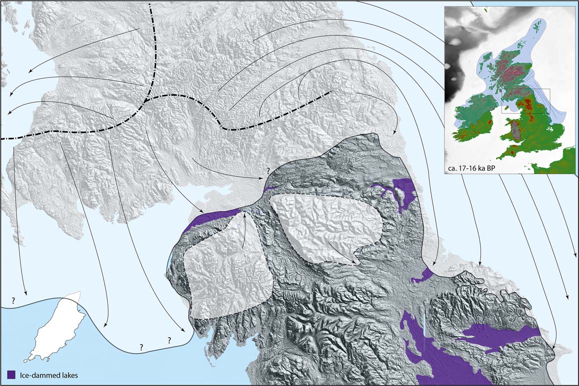
Decoupling of the Scottish and Irish Ice Sheets over the North Channel probably occurred between ∼16.5 ka and ∼16.0 ka (Clark et al. Reference Clark, Hughes, Greenwood, Jordan and Sejrup2012; Finlayson et al. Reference Finlayson, Fabel, Bradwell and Sugden2014), marking the end of ice occupance in the ISB. Retreat of Irish ice from the North Channel was succeeded by a readvance of ice from west-central Scotland across NE Ireland, the East Antrim Coastal Readvance. McCabe & Williams (Reference McCabe and Williams2012) reconstructed the limits of this readvance across 1800 km2 of NE Antrim, and argued that it occurred at ∼15.6–15.0 ka. This timing was challenged by Finlayson et al. (Reference Finlayson, Fabel, Bradwell and Sugden2014), who argued that it conflicts inter alia with older TCN exposure ages from the Isle of Arran. They envisaged that invasion of SW-flowing Scottish ice across NE Antrim represented ‘debuttressing' of the SW margin of the SIS following collapse of the Irish Ice Sheet around 16.5 ka, but both the timing and cause of this event remain uncertain.
7.5. The western sector of the last Scottish Ice Sheet
The western sector of the SIS comprised a northern zone, where ice from the Outer Hebrides Ice Cap extended an unknown distance westward across the northern Hebrides Shelf, and a southern zone, dominated by SW flow of the Hebrides Ice Stream towards the shelf edge.
7.5.1. The Outer Hebrides and adjacent Hebrides Shelf
The timing and pattern of retreat of the Outer Hebrides Ice Cap on the Hebrides Shelf is poorly constrained. Peacock et al. (Reference Peacock, Austin, Selby, Graham, Harland and Wilkinson1992) reported radiocarbon ages of 22.5±0.3 14C ka (26.7–26.0 cal 14C ka) for a shell from glacimarine deposits distal to moraine banks in the St Kilda basin ∼60 km W of North Uist, and 15.3±0.2 14C ka (18.3–17.9 cal 14C ka) for another from proximal glacimarine deposits on the same moraine banks. These dates indicate that the moraine banks were deposited by the last ice sheet, and that the ice margin retreated from this location before ∼18 ka. For the southern part of the Outer Hebrides Ice Cap, Small et al. (Reference Small, Benetti, Dove, Ballantyne, Fabel, Clark, Gheorghiu, Newall and Xu2017a) reported mean TCN ages of 18.9±1.1 ka for the deglaciation of Mingulay (but acknowledged that a single age of 17.3±0.9 ka may indicate later deglaciation) and 17.1±1.0 ka for the deglaciation of Barra, 27 km further N. A single (recalibrated) TCN age of 16.3±0.9 ka obtained for a bedrock sample from a col in South Uist (Stone & Ballantyne Reference Stone and Ballantyne2006) suggests prior deglaciation of much of the southern Outer Hebrides (Fig. 19).
Uncertainty-weighted means of terrestrial cosmogenic nuclide exposure ages indicating the timing of deglaciation, calibrated using the protocol outlined in section 2. Statistical outliers are excluded. Each age is followed by the full (±1σ) uncertainty, and the number of individual ages in the sample is shown in brackets. Single ages on the Outer Hebrides are shown for completeness, but should be treated with caution.
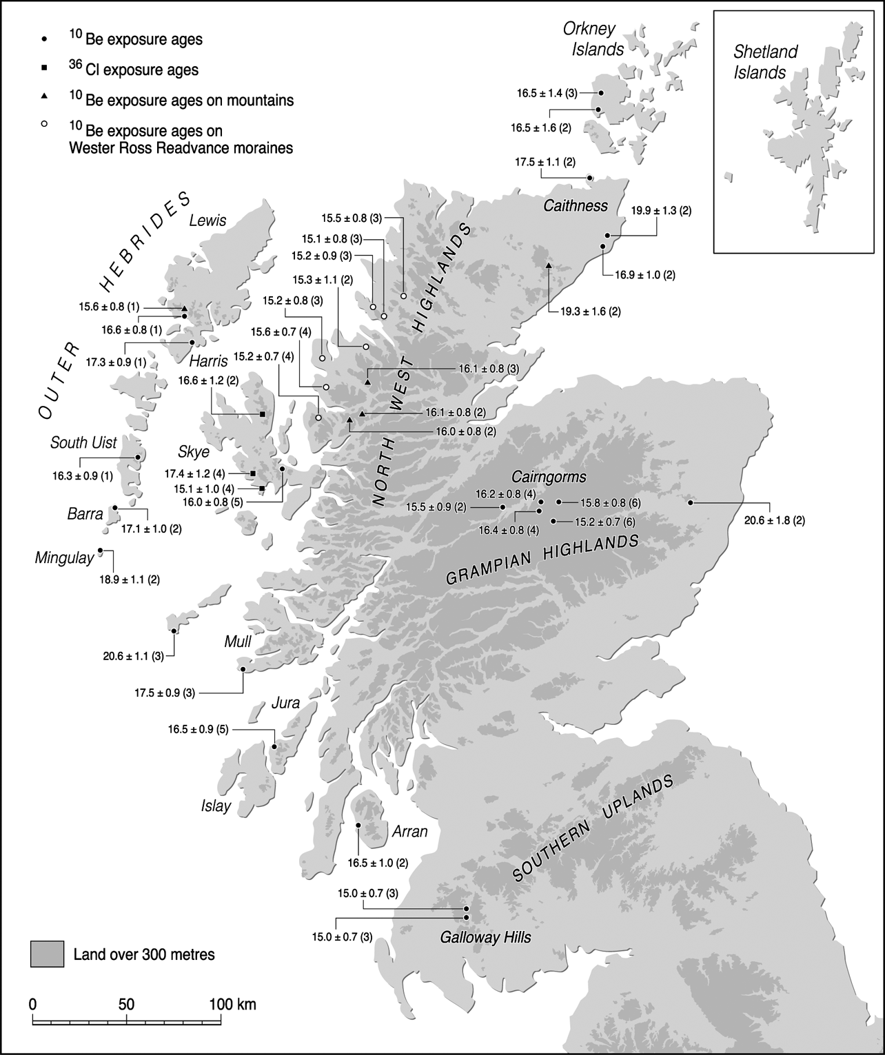
Three consistent TCN ages suggest that low ground in southern Harris was deglaciated by ∼17.9 ka (unpublished data), implying that by that time the retreating ice cap had split into a southern component occupying the Uists and a northern component centred on the mountains of N Harris. Stone & Ballantyne (Reference Stone and Ballantyne2006) obtained TCN ages for bedrock samples on low ground and cols in N Harris, but disparities amongst these suggest that most are compromised by nuclide inheritance. The two youngest (recalibrated) exposure ages indicate deglaciation by 17.3±0.9 ka on low ground and by 16.6±0.8 ka on a col at 425 m OD, and a single age of 15.6±0.8 ka for a sample from the summit of Oreval (662 m OD) suggests that ice may have persisted over high ground as late as 16–15 ka (Fig. 19). No data have been published for the timing of ice retreat on Lewis but, as noted in section 6.2.1, the early retreat of the Minch Ice stream and the limited extension of the Outer Hebrides Ice Cap west of Lewis (Bradwell & Stoker Reference Bradwell and Stoker2015a) suggest the early deglaciation of the coastal fringes of Lewis, followed by a gradual ice retreat to the mountains of Harris.
7.5.2. The southern Hebrides Shelf, Malin Shelf and Sea of the Hebrides
The current interpretation of maximum ice extent in this sector is that the Hebrides Ice Stream was confluent with a westward-flowing Malin Shelf Ice Stream (or ‘North Channel Ice Stream') that was fed by ice from the Firth of Clyde area, the North Channel ice divide and Ireland. During the LLGM, the confluent ice streams are thought to have terminated at the BDF (Greenwood & Clark Reference Greenwood and Clark2009; Dunlop et al. Reference Dunlop, Shannon, McCabe, Quinn and Doyle2010; Howe et al. Reference Howe, Dove, Bradwell and Gafeira2012; Ó Cofaigh et al. 2012; Finlayson et al. Reference Finlayson, Fabel, Bradwell and Sugden2014; Dove et al. Reference Dove, Arosio, Finlayson, Bradwell and Howe2015). Evidence for the early deglacial history of the Hebrides Ice Stream is scant. NW–SE-aligned moraine banks on the outer Malin Shelf, deposited by ice flowing from the NE (Dunlop et al. Reference Dunlop, Shannon, McCabe, Quinn and Doyle2010) suggest that the ice stream dominated the mid- and outer shelf during the early stages of retreat. TCN ages obtained for Bloody Foreland (the NW extremity of Ireland; Ballantyne et al. Reference Ballantyne, McCarroll and Stone2007; J. Clark et al. Reference Clark, McCabe, Schnabel, Clark, Freeman, Maden and Xu2009) and from Tiree (Small et al. Reference Small, Benetti, Dove, Ballantyne, Fabel, Clark, Gheorghiu, Newall and Xu2017a; Fig. 19) indicate deglaciation at ∼21 ka, suggesting that at this time the Hebrides Ice Stream had retreated to a line between these two points. The early deglaciation of Tiree (20.6±1.1 ka) and the much later deglaciation of the southernmost islands of the Outer Hebrides (18.9±1.1 ka or later; Small et al. Reference Small, Benetti, Dove, Ballantyne, Fabel, Clark, Gheorghiu, Newall and Xu2017a) supports the view of Dove et al. (Reference Dove, Arosio, Finlayson, Bradwell and Howe2015) that retreat of the ice stream occurred along calving margins above submarine troughs N and S of the Tiree-Coll platform. This interpretation implies that after ∼21 ka a marine embayment extended northward, progressively severing the Outer Hebrides Ice Cap from mainland ice, much as a similar embayment developed in the North Minch during the retreat of the Minch Ice Stream.
The timing of deglaciation of the Sea of the Hebrides is better established. TCN ages indicate the deglaciation of southern Skye by 17.4±1.2 ka, the Ross of Mull by 17.5 ± 0.9 ka and western Jura by 16.5±0.8 ka (Small et al. Reference Small, Rinterknecht, Austin, Bates, Benn, Scourse, Bourlès and Hibbert2016, 2017a; Fig 19), indicating that by ∼17.5–16.5 ka the ice margin was restricted to the fjords, islands and peninsulas of the western seaboard. A remarkable implication is that during the ∼3 ka separating the deglaciation of Tiree from that of southern Skye, southern Mull and Jura, the ice margin underwent net retreat of only 50–70 km in this sector. Cross-cutting bedforms and recessional moraines on the sea floor indicate flow reorganisation, increasing topographic control and readvances of the ice margin as it thinned and withdrew slowly to the E and NE (Howe et al. Reference Howe, Dove, Bradwell and Gafeira2012, Dove et al. Reference Dove, Arosio, Finlayson, Bradwell and Howe2015, 2016). Prolonged persistence of the ice margin within a narrow corridor amongst the Inner Hebrides was anticipated by Sissons (Reference Sissons1983), based on the distribution of high isostatically-uplifted coastal rock platforms that he attributed to post-deglaciation periglacial shore erosion. The implied slow net retreat of the ice margin across the onset zones of the Hebrides Ice Stream is consistent with the view of Small et al. (Reference Small, Benetti, Dove, Ballantyne, Fabel, Clark, Gheorghiu, Newall and Xu2017a) that it ceased to operate on a regional scale by the time of deglaciation of Tiree (21–20 ka).
8. Regional deglaciation 2: the Scottish mainland and Inner Hebrides
8.1. The NW Highlands and western seaboard
As noted in section 7.1, the configuration of ice-marginal moraines mapped by Bradwell & Stoker (Reference Bradwell and Stoker2015a) suggests a very early deglaciation of Cape Wrath and the early development of a marine embayment in the North Minch, with the ice margin subsequently retreating eastward into the fjords of the NW mainland (Fig. 12). The nature of the retreat in the Loch Ewe to Summer Isles area has been beautifully captured in bathymetric surveys (Stoker et al. Reference Stoker, Bradwell, Wilson, Harper, Smith and Brett2006, Reference Stoker, Bradwell, Howe, Wilkinson and McIntyre2009), which reveal numerous large crescentic or crenulate cross-fjord moraines 10–20 m high and up to 3 km long (Fig. 20) and smaller ridges interpreted as De Geer moraines, a submarine landsystem indicative of pulsed retreat of a grounded ice margin. Shells in cores recovered between the Summer Isles and the mouth of Loch Broom provide minimum deglaciation ages of 14.0–13.6 cal 14C ka and 13.8–13.6 cal 14C ka. From this and other evidence, Stoker et al. (Reference Stoker, Bradwell, Howe, Wilkinson and McIntyre2009) inferred deglaciation of this area at ∼14.5–13.0 ka. Recalibrated TCN ages for the Wester Ross Readvance, however, imply much earlier deglaciation, as outlined below.
Multibeam bathymetry of the seafloor in the vicinity of the Summer Isles, outer Loch Broom, showing multiple recessional moraines formed by readvances that interrupted ice margin retreat. From Bradwell et al. (Reference Bradwell, Stoker, Golledge, Wilson, Merritt, Long, Everest, Hestvik, Stevenson, Hubbard, Finlayson and Mathers2008a) Journal of Quaternary Science 23, 401–407. © 2008 NERC. Reproduced with permission from John Wiley & Sons Ltd.

The oldest TCN exposure ages in Wester Ross relate to erratic boulders deposited on the summit blockfields of Maol Chean-dearg, Beinn Liath Mhór and Slioch at altitudes of 916–967 m OD (Fabel et al. Reference Fabel, Ballantyne and Xu2012; Figs 14, 19, 22). Excluding outliers, these yielded (recalibrated) uncertainty-weighted mean ages of 16.0±0.8 k, 16.1±0.8 ka and 16.1±0.8 ka respectively, suggesting that mountain summits emerged from the thinning ice sheet as nunataks at ∼16 ka.
Most dating evidence for the retreat of the ice margin in NW Scotland relates to the moraines that mark the limit of the Wester Ross Readvance (WRR), which is intermittently defined by terrestrial moraines between the Applecross Peninsula and Achiltibuie (Robinson & Ballantyne Reference Robinson and Ballantyne1979; Sissons & Dawson Reference Sissons1981; Sutherland Reference Sutherland1984; Figs 21, 22), and designated individually as the Applecross, Redpoint, Gairloch, Aultbea and Achiltibuie moraines. Everest et al. (Reference Everest, Bradwell, Fogwill and Kubik2006) obtained six TCN ages for erratics on the Gairloch moraine, but even after the rejection of two dates as outliers, these yielded (recalibrated) ages of 20.4±3.6 ka to 14.1±2.1 ka, which permit no valid conclusions. Conversely, eight consistent TCN ages with an apparent average age of ∼13.5 ka were reported by Bradwell et al. (Reference Bradwell, Stoker, Golledge, Wilson, Merritt, Long, Everest, Hestvik, Stevenson, Hubbard, Finlayson and Mathers2008a) for samples from boulders on the Achiltibuie moraine, a lateral moraine above Little Loch Broom, and another in the Loanan Valley in Assynt. They concluded from these results and the record of submarine moraines between Loch Ewe and Loch Broom that “substantial dynamic ice caps existed in NW Scotland between 13 and 14 ka” (Bradwell et al. Reference Bradwell, Stoker, Golledge, Wilson, Merritt, Long, Everest, Hestvik, Stevenson, Hubbard, Finlayson and Mathers2008a, p. 401), a conclusion further developed by Stoker et al. (Reference Stoker, Bradwell, Howe, Wilkinson and McIntyre2009).
Wester Ross Readvance moraines: (a) the Applecross moraine crosses the photograph from left to right between the two lochans; (b) the central section of the Gairloch moraine, which is composed of Torridon Sandstone boulders and occasional Lewisian Gneiss erratics. The former glacier was located to the right (east) of the ridge.

Moraines marking the limits of the Wester Ross Readvance, showing the sites sampled by Bradwell et al. (Reference Bradwell, Stoker, Golledge, Wilson, Merritt, Long, Everest, Hestvik, Stevenson, Hubbard, Finlayson and Mathers2008a; sites 1, 2 and 4) and Ballantyne et al. (Reference Ballantyne, Schnabel and Xu2009a; sites 3, 5, 6 and 7) for cosmogenic 10Be exposure dating of boulders on moraines. From Ballantyne & Stone (Reference Ballantyne and Stone2012), Journal of Quaternary Science 27, 297–306. © 2011 John Wiley & Sons Ltd.
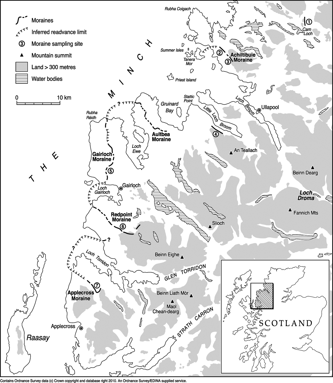
This proposition was initially supported by 14 10Be exposure ages obtained by Ballantyne et al. (Reference Ballantyne, Schnabel and Xu2009a) for boulders on the Applecross, Gairloch, Redpoint and Achiltibuie moraines. These yielded apparent mean ages of 14.0–13.5 ka, almost identical to the eight TCN ages reported by Bradwell et al. (Reference Bradwell, Stoker, Golledge, Wilson, Merritt, Long, Everest, Hestvik, Stevenson, Hubbard, Finlayson and Mathers2008a), and indicate that all the dated moraines represent an isochronous, or nearly isochronous, readvance of the ice margin. Subsequent recalibration of all 22 TCN ages using a locally-derived 10Be production rate, however, showed that the initially reported ages are too young (Ballantyne & Stone Reference Ballantyne and Stone2012). Recalibration of these ages using the protocol adopted here yields an uncertainty-weighted mean age of 15.3±0.7 ka for the WRR (Fig. 23). This revised age implies a much earlier retreat of the ice margin across low ground in Wester Ross, consistent with Lateglacial pollen-stratigraphic evidence from Loch Droma on the watershed inland from Wester Ross. Though the radiocarbon age of 15.6–15.1 cal 14C ka obtained by Kirk & Godwin (Reference Kirk and Godwin1963) for this site (Fig. 24) may be compromised by ‘old' carbon residues, the associated pollen assemblages appear to span the entire Lateglacial Interstade (Pennington et al. Reference Pennington, Haworth, Bonny and Lishman1972). If so, most or all of the low ground in Wester Ross must have been deglaciated between the WRR at 15.3±0.7 ka and the onset of the Lateglacial Interstade at ∼14.7 ka. Deglaciation of low ground further N was probably earlier. An age of 15.9–15.2 cal 14C ka for organic material near the base of a core from Cam Loch in Assynt is minimal for deglaciation (Pennington Reference Pennington1975). Similarly, Boomer et al. (Reference Boomer, von Grafenstein and Moss2012) obtained an age of 14.4–14.1 cal 14C ka from near the base of a core from Loch Assynt, and inferred from their age–depth model that deglaciation occurred before ∼17 ka.
Summed normal kernel density estimates of recalibrated cosmogenic 10Be exposure ages and their uncertainties for boulder samples from Wester Ross Readvance moraines. Upper line: all 22 samples; weighted mean age 15.28±0.69 ka. Middle line: 14 ages originally reported by Ballantyne et al. (Reference Ballantyne, Schnabel and Xu2009a); weighted mean age 15.31±0.70 ka. Lower (dashed) line: eight ages originally reported by Bradwell et al. (Reference Bradwell, Stoker, Golledge, Wilson, Merritt, Long, Everest, Hestvik, Stevenson, Hubbard, Finlayson and Mathers2008a); weighted mean age 15.23±0.71 ka.

Key terrestrial and nearshore radiocarbon ages that constrain the timing of ice-sheet deglaciation, showing the extent of glacier ice during the Younger Dryas Stade (∼12.9–11.7 ka). Ages are expressed as calibrated ±1σ age ranges (cal 14C ka). Most nearshore and coastal ages were obtained from molluscs or foraminifera, and inland ages represent the oldest date obtained from organic material in cores recovered from lakes or infilled depressions. For a few sites two or more ages have been aggregated and the combined ±1σ age range is shown. All ages represent minima for deglaciation. Ages shown with a question mark may be too old.
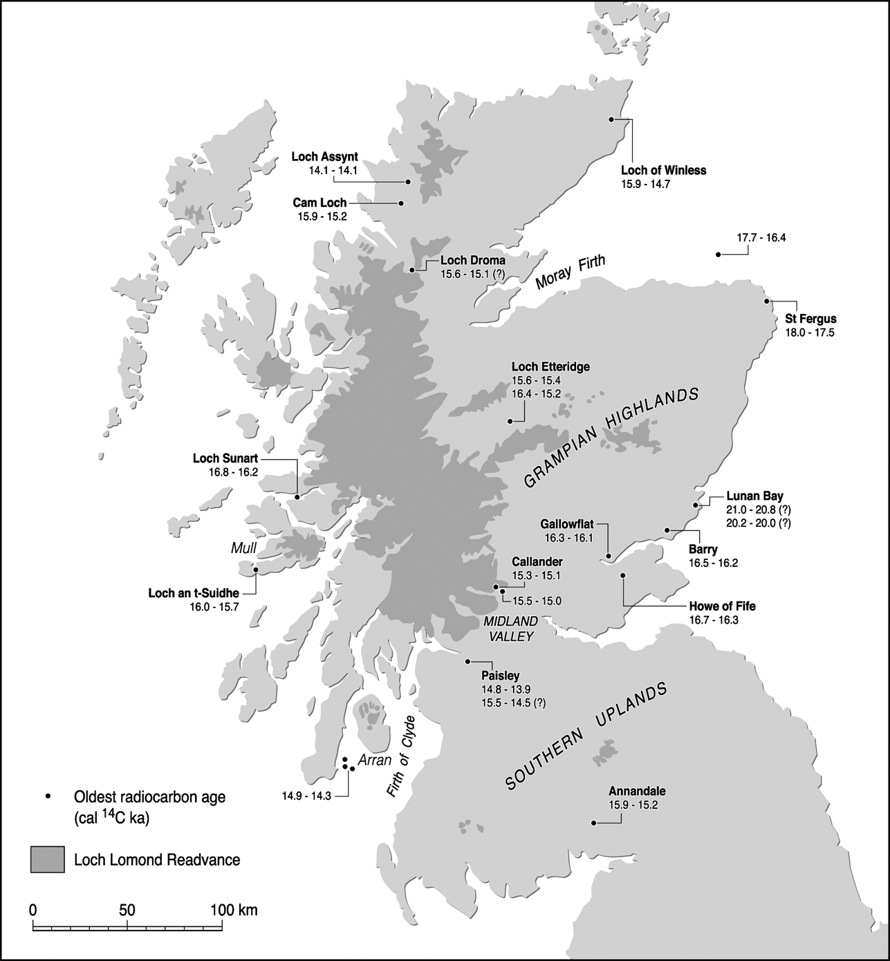
Retreat of the ice margin along the NE coast of Skye, first southwards along the Sound of Raasay and then eastwards towards the mainland, is constrained by TCN ages. Two consistent TCN ages for ice-abraded bedrock at 450 m OD in southern Trotternish (Stone et al. Reference Stone, Ballantyne and Fifield1998; Fig. 19) give a recalibrated mean age of 16.6±1.2 ka, and five samples from boulders on a medial moraine near Broadford yield a recalibrated mean age of 16.0±0.8 ka (Small et al. Reference Small, Rinterknecht, Austin, Fabel, Miguens-Rodriguez and Xu2012). The latter age implies that the ice margin backstepped on to the adjacent mainland after ∼16 ka, consistent with the timing of the WRR (15.3±0.7 ka) on the adjacent Applecross peninsula.
Elsewhere on Skye, there is stratigraphic and geomorphological evidence that the retreat of the mainland ice sheet was succeeded by an expansion of a residual ice cap centred over high ground in the south-central part of the island (Benn Reference Benn1997). In lower Glen Brittle, the up-valley termination of a high Lateglacial shoreline coincides with end moraines marking the limit of ice advance down the glen (Walker et al. Reference Walker, Ballantyne and Lowe1988). Four cosmogenic 36Cl exposure ages obtained from boulders on these moraines give a weighted mean age of 17.4±1.2 ka (Small et al. Reference Small, Rinterknecht, Austin, Bates, Benn, Scourse, Bourlès and Hibbert2016), implying prior disengagement of mainland ice from the Skye ice cap, but the range of individual ages is wide (19.4±1.7 ka to 15.5±1.7 ka). In southern Skye, bathymetric mapping of Loch Scavaig has revealed a pronounced arcuate submarine end moraine that impinges on the adjacent island of Soay, and samples from erratic basalt boulders on the Soay moraine have produced four 36Cl ages of 16.4±1.5 ka to 14.6±1.5 ka, with a weighted mean age of 15.1±1.0 ka. The closeness of this age to that of the WRR moraines (15.3±0.7 ka) suggests contemporaneity, although Small et al. (Reference Small, Rinterknecht, Austin, Bates, Benn, Scourse, Bourlès and Hibbert2016) cautioned against definitive correlation of the two because of uncertainties in the derivation of the mean exposure age for the Soay moraine.
Farther south, the TCN age of 17.5±0.9 ka obtained for the Ross of Mull (Small et al. Reference Small, Benetti, Dove, Ballantyne, Fabel, Clark, Gheorghiu, Newall and Xu2017a; Fig. 19) is consistent with a basal age of 16.0–15.7 cal 14C ka for the onset of organic sedimentation in nearby Loch an t-Suidhe (Walker & Lowe Reference Walker and Lowe1982), the latter being minimal for deglaciation. North of Mull, a radiocarbon age of 16.8–16.2 cal 14C ka for a shell in a core recovered from outer Loch Sunart (Baltzer et al. Reference Baltzer, Bates, Mokeddem, Clet-Pellerin, Walter-Simonnet, Bonnot-Courtois and Austin2010) indicates prior deglaciation of the Ardnamurchan Peninsula and western Moidart (Fig. 24). On Jura, a medial moraine formed by a landslide onto the thinning ice sheet yielded a TCN age of 16.5±0.8 ka (Small et al. Reference Small, Benetti, Dove, Ballantyne, Fabel, Clark, Gheorghiu, Newall and Xu2017a), consistent with TCN ages obtained for nearby postglacial rockslide deposits (∼15.4–13.7 ka), which are minimal for deglaciation (Ballantyne et al. Reference Ballantyne, Wilson, Gheorghiu and Rodés2014). Numerous recessional moraines recorded on the seafloor of the Firth of Lorne and Sound of Jura indicate the subsequent oscillatory retreat of a grounded ice margin (Howe et al. Reference Howe, Dove, Bradwell and Gafeira2012; Dove et al. Reference Dove, Arosio, Finlayson, Bradwell and Howe2015, Reference Dove, Finlayson, Bradwell, Howe and Arioso2016).
The available geochronological evidence for the western seaboard therefore indicates deglaciation of the extreme NW, and of parts of Skye and Mull, before ∼17 ka. By ∼16 ka, the margin of mainland ice had backstepped from most of the Inner Hebrides and the westernmost mainland peninsulas, and mountain summits were emerging from the ice sheet. By 15 ka, following the WRR, the mainland ice margin had probably retreated east of the coastline, though residual ice masses may have occupied the mountains of Skye and possibly Mull. The subsequent deglacial history of this sector is difficult to assess, as many of the fjords and valleys of western Scotland were reoccupied by glaciers during the Younger Dryas Stade.
8.2. Caithness, NE Scotland and eastern Scotland
8.2.1. Caithness
Hall & Riding (2016) inferred from stratigraphic, geomorphological and flowline evidence that an eastward retreat of the ice margin in the Pentland Firth was succeeded by a restricted readvance of Moray Firth ice northwestward into the firth, accompanied and succeeded by a northeastward flow of ice from the Northern Highlands. The latter may have occupied central Caithness as Moray Firth ice retreated, first southeastwards then southwestwards along the east coast. Till sheets and moraine systems record late readvances of ice moving NE and E from the Caithness–Sutherland border.
Recalibration of TCN ages reported by Phillips et al. (Reference Phillips, Hall, Ballantyne, Binnie, Kubik and Freeman2008) suggests two interpretations for the timing of deglaciation in Caithness. Two TCN ages for bedrock samples from a col at 445 m OD on Morven in central Caithness gave a mean age of 19.3±1.6 ka, and a bedrock-boulder pair from Hill of Yarrows (10 km S of Wick) produced a mean age of 19.9 ± 1.3 ka (Fig. 19). Both results suggest the deglaciation of much of eastern Caithness before ∼19 ka. Conversely, two samples from Dunnet Head in northernmost Caithness yielded a weighted mean age of 17.5±1.1 ka, and two from Clyth (5 km SW of Hill of Yarrows) gave a weighted mean age of 16.9±1.1 ka. These younger ages appear more realistic for the timing of deglaciation, given (1) the deglaciation age of 16.5±1.2 ka inferred for the deglaciation of low ground in Orkney; (2) a radiocarbon age of 15.9–14.7 cal 14C ka obtained for the oldest organic sediments in Loch of Winless near Wick (Peglar Reference Peglar1979); and (3) the timing of the retreat of ice in the Moray Firth (see below). They suggest that the retreat of Moray Firth ice across Caithness mainly occurred within the period 17.5–17.0 ka, with a later expansion of ice from high ground to the west (Hall & Riding 2016).
8.2.2. The Moray Firth and NE Scotland
Lithostratigraphic and flowset evidence (Merritt et al. Reference Merritt, Auton, Connell, Hall and Peacock2003; Hughes et al. Reference Hughes, Clark and Jordan2014) indicates that following the LLGM there was major reorganisation of ice flow in NE Scotland. Merritt et al. (Reference Merritt, Connell and Hall2017) envisaged that within the period ∼22–19 ka, predominantly cold-based ice flowing E from the eastern Grampians and Cairngorms was surrounded along coastal areas by a pincer movement of ice flowing E then SE from the Moray Firth and NE-flowing ice from Strathmore (Fig. 25a). They concluded that initial deglaciation on land occurred near the confluence of these three ice masses, inland from Peterhead, but was succeeded by a localised readvance, the Logie–Buchan Readvance. They also suggested that the subsequent disengagement of Grampian and Strathmore ice led to the deglaciation of the east coast from Peterhead to the Tay estuary by ∼20.9–20.1 ka (Fig. 25b), as indicated by radiocarbon ages obtained from foraminifera in raised marine muds at Lunan Bay (McCabe et al. Reference McCabe, Clark, Smith and Dunlop2007; see below).
(a) Pattern of ice movement in eastern Scotland following opening of a marine embayment to the Witch Ground Basin (red hexagon) depicted by Merritt et al. (Reference Merritt, Connell and Hall2017). (b) Subsequent retreat of Strathmore ice and deglaciation of eastern Scotland depicted by the same authors. Dashed lines represent flow directions, and thick lines with open diamonds denote ice divides. From Merritt et al. (Reference Merritt, Connell and Hall2017) Journal of Quaternary Science 32, 276–294. © 2016 John Wiley & Sons, Ltd.

The extent of Moray Firth ice during the period 22–19 ka is uncertain. At St Fergus, on the Buchan coast near Peterhead, a moraine formed by a localised readvance of Moray Firth ice from the E or NE contains glacitectonised marine sediments, and a radiocarbon age of 15,320±200 14C a BP (18.0–17.5 cal 14C ka) obtained for a shell in raised marine silts indicates prior ice-free conditions (Hall & Jarvis 1989) and provides a minimum age for the readvance. Organic material within a core recovered from marine silts in the Moray Firth itself, ∼17 km NE of Banff, yielded radiocarbon ages ranging from 20.9–19.3 cal 14C ka to 17.7–16.4 cal 14C ka (Harkness & Wilson Reference Harkness and Wilson1979), the youngest age suggesting that the ice margin had retreated to this position by ∼17 ka. Subsequent ponding of lakes along the N coast of Buchan implies that the margin of the Moray Firth lobe lay along this coast after deglaciation of inland areas, and there is evidence for a readvance near Elgin, which Merritt et al. (Reference Merritt, Connell and Hall2017) assigned to ∼15 ka, although earlier deglaciation seems likely. A further oscillation of the retreating ice margin occurred at Ardesier near Inverness, where a moraine containing glacitectonised glacimarine silts indicates that the retreat of a calving tidewater margin in response to rising sea level was interrupted by a readvance, tentatively assigned to ∼13 14C ka (∼15.6 cal 14C ka) by Merritt et al. (Reference Merritt, Auton and Firth1995). The ice margin then retreated into Loch Ness, at that time a fjord open to the sea. Recessional moraines in the north of the loch indicate the punctuated retreat of a grounded ice margin, followed by deposition of a large moraine (the Foyers rise) midway down the loch, then a rapid retreat towards Fort Augustus, where evidence of subsequent events is lost under Younger Dryas deposits (Turner et al. Reference Turner, Woodward, Dunning, Shine, Stokes and Ó Cofaigh2012).
8.2.3. Eastern Scotland
Present understanding of the timing of SIS retreat in E Scotland is based largely on the radiocarbon dating of marine shells or foraminifera within raised glacimarine or marine muds deposited after deglaciation. Radiocarbon ages of 17,720±50 and 17,050±50 14C a BP (21.0–20.8 and 20.2–20.0 cal 14C ka) for samples of Elphidium clavatum in raised marine muds at Lunan Bay near Montrose provide the earliest evidence of the retreat of the ice margin to the east coast of Scotland (McCabe et al. Reference McCabe, Clark, Smith and Dunlop2007). The most widely-distributed raised muds are those of the Errol Clay Formation, which occurs along the Tay and Forth estuaries and valleys. These contain a sparse high-arctic marine fauna and are thought to have been deposited rapidly as the ice margin retreated (Peacock Reference Peacock1999). Radiocarbon dating of marine shells within the Errol Clay Formation in the Tay estuary area has yielded a wide range of ages (16.5–16.2 14C ka at Barry, near the mouth of the Tay estuary, to 14.6–14.1 cal 14C ka farther inland); the oldest ages for Gallowflat, 14 km E of Perth (16.3–16.1 cal 14C ka), imply the deglaciation of the Firth of Tay prior to ∼16.3 ka (Peacock Reference Peacock2003; McCabe et al. Reference McCabe, Clark, Smith and Dunlop2007; Fig. 24).
Although the deglaciation ages (21.0–20.8 cal 14C ka and 20.2–20.0 cal 14C ka) obtained by McCabe et al. (Reference McCabe, Clark, Smith and Dunlop2007) for raised marine muds at Lunan Bay are consistent with two (recalibrated) TCN ages averaging 20.6±1.8 ka for an inland site at Pitfichie, 50 km further N (Phillips et al. Reference Phillips, Hall, Ballantyne, Binnie, Kubik and Freeman2008; Fig. 19), these dates pose a conundrum. They appear incompatible with the inferred timing (∼18.5 ka) of the decoupling of the SIS and FIS in the NSB as proposed by Sejrup et al. (Reference Sejrup, Clark and Hjelstuen2016), and with the reconstructions of BIIS retreat stages based on flowsets (Hughes et al. Reference Hughes, Clark and Jordan2014) or other geomorphological evidence (Clark et al. Reference Clark, Hughes, Greenwood, Jordan and Sejrup2012, Fig. 16). Conversely, they are consistent with the southward extension of a marine embayment separating the SIS and FIS envisaged by Bradwell et al. (Reference Bradwell, Stoker, Golledge, Wilson, Merritt, Long, Everest, Hestvik, Stevenson, Hubbard, Finlayson and Mathers2008b), Merritt et al. (Reference Merritt, Connell and Hall2017) and others (Fig. 25). These dates imply that a deglaciated enclave existed in eastern Scotland three to four millennia before the proposed timing of the Fladen 1 and Fladen 2 readvances into the Witch Ground Basin (Sejrup et al. Reference Sejrup, Hjelstuen, Nygård, Haflidason and Mardal2015), and the possible extension of ice to east Yorkshire (Bateman et al. Reference Bateman, Evans, Roberts, Medialdea, Ely and Clark2017). They also suggest that the net retreat of the ice margin from Lunan Bay to Barry, a distance of ∼23 km, took ∼3000–4000 years.
There are two solutions to the apparent paradoxes raised by the Lunan Bay dates. One is that the dates are too old. The alternative is that deglaciation of the E coast occurred prior to 21–20 ka and that there were subsequent readvances and surges of the ice margin both north and south of the deglaciated enclave, as illustrated by Clark et al. (Reference Clark, Hughes, Greenwood, Jordan and Sejrup2012). McCabe et al. (Reference McCabe, Clark, Smith and Dunlop2007) inferred from the presence of kettled outwash gravels overlying the raised marine muds at Lunan Bay that ice had subsequently readvanced across this site. This evidence is compelling, though there is no evidence of intervening till or of glacitectonic deformation of the marine muds (Peacock et al. Reference Peacock, Armstrong, Browne, Golledge and Stoker2007). They also revived the concept of a later readvance of ice in eastern Scotland, the Perth Readvance, based on similar stratigraphic evidence (laminated muds and silty-sands overlain by kettled outwash gravels) at Bertha Park, 3 km NW of Perth. The concept of a widespread Perth Readvance of ice flowing out of the glens of the southern and SE Grampians and eastward into the Tay and Forth Valleys has a long and contested history (Simpson Reference Simpson1933; Sissons Reference Sissons1963, Reference Sissons1964, Reference Sissons1967, Reference Sissons1974; Paterson Reference Paterson1974), and although the limits and extent of this event remain uncertain, it is possibly consistent with the areal extent of a prominent raised shoreline (the main Perth raised shoreline) in the Forth and Tay valleys (Sissons & Smith Reference Sissons and Smith1965; Sissons et al. Reference Sissons, Smith and Cullingford1966; Cullingford Reference Cullingford, Gray and Lowe1977). If the laminated muds at Bertha Park are stratigraphically equivalent to the Errol Clay Formation at Gallowflat, then the readvance must have occurred after ∼16.3 ka. McCabe et al. (Reference McCabe, Clark, Smith and Dunlop2007) suggested that the Perth Readvance may be correlated with the Killard Point Readvance in NE Ireland (McCabe et al. Reference McCabe, Clark and Clark2005), though reassessment of the timing of the latter suggests that it occurred earlier, within the interval ∼17.3–16.6 ka (Ballantyne & Ó Cofaigh Reference Ballantyne, Ó Cofaigh, Coxon, McCarron and Mitchell2017).
8.2.4. Strathspey, the Cairngorms and the eastern Grampians
The distribution of schist erratics indicates that the Cairngorms acted as an independent centre of ice dispersal throughout the last glacial cycle (Sugden Reference Sugden1970), diverting ice from the Grampians into Strathspey and the Dee valley, where overall retreat was interrupted by readvances or stillstands (Brown Reference Brown1993). There is abundant dating evidence for deglaciation of the Cairngorms and surrounding areas. Postglacial rockslide debris (possibly onto decaying ice) in Strath Nethy and the Lairig Ghru has produced recalibrated mean 10Be ages of 18.2±1.1 ka and 17.1±1.0 ka respectively (Ballantyne et al. Reference Ballantyne, Schnabel and Xu2009b), tentatively suggesting the early deglaciation of some valleys within the massif, and a single TCN age of 16.9±1.1 ka for an erratic at 1156 m OD on Cnap à Chléirich may indicate the approximate timing of deglaciation of high ground (Phillips et al. Reference Phillips, Hall, Mottram, Fifield and Sugden2006).
The retreat of ice in Strathspey is marked by lateral moraines and meltwater channels along the northern flanks of the Cairngorms, and the decoupling of Strathspey ice from the Cairngorm ice cap resulted in the formation of ice-dammed lakes in some valleys (Brazier et al. Reference Brazier, Kirkbride and Gordon1998; Golledge Reference Golledge2002). Samples from boulders on moraines associated with a former ice-dammed lake in the NW Cairngorms have yielded a mean recalibrated age of 16.2±0.8 ka for the margin of the Strathspey ice that dammed one lake, and of 16.4±0.8 ka for the margin of local ice entering the lake (Everest & Kubik Reference Everest, Bradwell, Fogwill and Kubik2006; Fig. 19). Boulder samples from high-level (540–750 m OD) lateral moraines marking the S margin of Strathspey ice in the NE Cairngorms gave a recalibrated mean age (excluding outliers) of 15.8±0.8 ka, interpreted by Hall et al. (2016a) as the timing of a readvance of Strathspey ice to near Grantown. The location of the moraines dated by Hall et al. (2016a) implies that these must have been deposited earlier than the more westerly moraines dated by Everest & Kubik (Reference Everest, Bradwell, Fogwill and Kubik2006), but the two sets of 10Be ages are statistically indistinguishable, and together indicate that retreat of Strathspey ice along the northern flank of the Cairngorms occurred at ∼16.5–15.5 ka. This timing is consistent with radiocarbon ages obtained for basal organic sediments from Loch Etteridge in the upper Spey Valley: 13,150±390 14C a BP (Sissons & Walker Reference Sissons1974) and 12,930±40 14C a BP (Everest & Golledge Reference Everest, Golledge, Lukas, Merritt and Mitchell2004); equivalent to 16.4–15.2 cal 14C ka and 15.6–15.4 cal 14C ka, respectively.
Three TCN ages for boulders on till ridges at ∼640 m OD in the Monadhliath Mountains, ∼10 km NNW of Loch Etteridge were originally interpreted by Gheorghiu et al. (Reference Gheorghiu, Fabel, Hansom and Xu2012) as representing the timing of ice-sheet deglaciation. Recalibration of their data produced a range of ages (18.7±1.0, 16.4±0.9 and 13.4±0.7 ka) that is too wide to permit meaningful inference. However, two boulder samples they obtained from a drift ridge in nearby Glen Banchor produced (recalibrated) 10Be ages of 15.8±1.3 and 15.4±0.9 ka (Fig. 19). These ages are consistent with the Loch Etteridge radiocarbon dates and imply a retreat of the ice margin to the upper Spey valley by 15.5±0.9 ka. Six 10Be ages obtained by Everest & Kubik (Reference Everest and Kubik2006) for boulders on drift ridges near the mouth of Glen Geusachan (southern Cairngorms) are problematic. The recalibrated ages range from 18.6±1.6 ka to 13.6±1.4 ka with a mean age of 15.2±0.7 ka. Given the range of ages, the acceptance of the mean age as representative of the timing of deposition is not statistically justifiable, and the significance of these dates is unclear.
In summary: (1) some valleys within the Cairngorms may have been deglaciated when ice from the SW still encircled most of the massif; (2) there is reasonable evidence to suggest that the Strathspey ice lobe withdrew from the northern Cairngorms within the period ∼16.5–15.5 ka; and (3) there is convincing evidence to indicate the deglaciation of the upper Spey Valley by ∼15.5 ka, long before the beginning of the Lateglacial Interstade at ∼14.7 ka.
8.3. Deglaciation of southern and central Scotland
8.3.1. Southern Scotland
Using a combination of radiocarbon dating and TCN exposure dating, Livingstone et al. (Reference Livingstone, Roberts, Davies, Evans, Ó Cofaigh and Gheorghiu2015) showed that the ice margin had retreated into the Solway Lowlands before 16.4–15.7 ka, and this is supported by a basal age of 15.9–15.2 cal 14C ka for a site in Annandale near Lockerbie (Bishop & Coope Reference Bishop, Coope, Gray and Lowe1977; Fig. 24). The high-arctic fauna in raised marine muds in SW Galloway suggests contemporaneity with the Errol Clay Formation in eastern Scotland (Peacock Reference Peacock and Gemmell1975), suggesting deglaciation before ∼16.5–15.5 ka. TCN ages for two sites in the heart of the Galloway Hills (Fig. 19) have produced identical recalibrated mean ages of 15.0±0.7 ka (Ballantyne et al. Reference Ballantyne, Rinterknecht and Gheorghiu2013), implying that ice had almost disappeared from SW Scotland by ∼15 ka. It seems likely that the rest of the Southern Uplands was also extensively deglaciated by that time, though there is no geochronological evidence to confirm this.
8.3.2. East and central Midland Valley
Early deglaciation of E Fife is indicated by six raised shorelines that exhibit a marked eastward tilt due to subsequent differential glacio-isostatic uplift (Cullingford & Smith Reference Cullingford and Smith1966). Five of these shorelines have been identified at sites as far north as Stonehaven (Cullingford & Smith Reference Cullingford and Smith1980), suggesting that eastern Fife may have been deglaciated as early as ∼21–20 ka, based on the radiocarbon ages obtained by McCabe et al. (Reference McCabe, Clark, Smith and Dunlop2007) at Lunan Bay (see section 8.2.3 above). It is difficult, however, to reconcile this inference with the proposal that ice from the Grampians and the Midland Valley participated in a readvance of the North Sea Lobe to the Yorkshire coast at ∼16.8 ka to deposit the Withernsea Till at Dimlington (Roberts et al. Reference Roberts, Dackombe and Thomas2013; Livingstone et al. Reference Livingstone, Roberts, Davies, Evans, Ó Cofaigh and Gheorghiu2015; Bateman et al. Reference Bateman, Evans, Roberts, Medialdea, Ely and Clark2017). Moreover, organic debris from silts overlying marine clays in the Howe of Fife has yielded a radiocarbon age of 16.7–16.3 cal 14C ka (Harkness & Wilson Reference Harkness and Wilson1979), and basal organic deposits in Black Loch, in northern Fife, have been dated to 15.4–14.8 cal 14C ka (Whittington et al. Reference Whittington, Edwards and Caseldine1991). Both ages are minimal for deglaciation, but imply that most of Fife was probably ice free before ∼16.5 ka.
The timing of deglaciation across the southern Midland Valley has not been established, but Sutherland (Reference Sutherland1984) noted that meltwater channels from Ayrshire to the Forth are aligned ENE, implying that deglaciation of a broad swath of lowland terrain occurred when the ice divide was located over the Firth of Clyde, and hence that these areas and the Forth Valley were deglaciated before the retreat of ice from west-central Scotland. The final retreat of ice from the central Midland Valley is constrained by radiocarbon ages from sites near Callander on the Highland boundary (Fig. 24). Lowe (Reference Lowe1978) obtained an age of 12,750±120 14C a BP (15.5–15.0 cal 14C) from basal organic deposits in a kettle hole, and Merritt et al. (Reference Merritt, Coope, Taylor and Walker1990) obtained an age of 12,750±70 14C a BP (15.3–15.1 cal 14C ka) for lacustrine deposits underlying Younger Dryas till. These ages suggest that the entire eastern and central Midland Valley was ice free before ∼15.2 ka.
8.3.3. West Central Scotland and the Clyde Estuary
The pattern of deglaciation in this area has been reconstructed by Finlayson et al. (Reference Finlayson, Merritt, Browne, Merritt, McMillan and Whitbread2010, Reference Finlayson, Fabel, Bradwell and Sugden2014) from geomorphological and stratigraphic evidence. They inferred that at ∼16.5 ka, all of west-central Scotland was still covered by ice, with ice from the SW Highlands flowing E into the upper Forth valley, SE up the Clyde Valley and down the Firth of Clyde to impinge on NE Ireland. Subsequent northwards and northwestwards retreat resulted in a decoupling from Southern Uplands ice and the deglaciation of much of Ayrshire, with ice-dammed lakes forming in the Clyde and Irvine valleys, whilst a substantial glacier continued to occupy the Firth of Clyde. The final stage of deglaciation involved the retreat of the ice margin to the mouths of the fjords (such as Loch Fyne and Loch Long) that formed the arteries of ice movement from the SW Highlands. Deposition of moraine belts at Kilmarnock, Blantyreferm in the Clyde Valley and Eaglesham imply that overall retreat was interrupted by localised readvances or stillstands, suggesting that the retreating ice margin remained climatically active.
Retreat of the ice from the Firth of Clyde resulted in a marine transgression across low-lying coasts and the deposition of the glacimarine or marine Clyde Clay Formation at altitudes of up to 40 m OD. These deposits incorporate molluscan assemblages of typically high boreal to low arctic provenance (Peacock & Harkness Reference Peacock and Harkness1990), in contrast to the high-arctic affiliation of the Errol Clay Formation fauna of eastern Scotland, implying that the final stages of glacier retreat in the Clyde basin occurred later, under milder conditions.
The timing of the initial ice retreat from the outer Firth of Clyde is difficult to establish. The lowest molluscan assemblages in cores from boreholes south of Arran (Fig. 24) were interpreted by Peacock et al. (Reference Peacock, Horne and Whittaker2012) as being of Lateglacial Interstadial (∼14.7–12.9) age, and the oldest radiocarbon ages from these cores (14.9–14.3 cal 14C ka) are consistent with this interpretation. However, Peacock et al. (Reference Fyfe, Long and Evans2012) also detected reworked high-arctic fauna at the base of these cores, indicating that the area was deglaciated sometime before ∼14.7 ka. Finlayson et al. (Reference Finlayson, Fabel, Bradwell and Sugden2014) placed deglaciation of the Firth of Clyde south of Arran much earlier, on the basis of two TCN ages with a mean recalibrated age of 16.5±1.0 ka for boulders from moraines at Glen Dougarie on Arran. If valid, this date implies a rapid advance (the East Antrim Coastal Readvance) then retreat of Clyde ice following the Killard Point Readvance (∼17.3–16.6 cal 14C ka) in NE Ireland (Ballantyne and Ó Cofaigh Reference Ballantyne, Ó Cofaigh, Coxon, McCarron and Mitchell2017). On present evidence, it appears that much of the Firth of Clyde was deglaciated sometime between ∼16.5 ka and ∼14.7 ka but, taking into account the wider evidence from Ireland, retreat after ∼16 ka seems likely.
A large number of radiocarbon ages, mostly within the range 13.0–11.5 14C ka, have been obtained for marine shells in the Clyde Clay Formation, but few are sufficiently consistent to constrain the timing of deglaciation (Sutherland Reference Sutherland1986). A clutch of ages obtained for Arctica islandica shells from near the head of the Clyde estuary around Paisley, however, indicate deglaciation prior to 14.8–13.9 cal 14C ka, with one older sample yielding an age of 15.5–14.5 cal 14C ka (Sutherland Reference Sutherland1986; Peacock & Harkness Reference Peacock and Harkness1990). The molluscan fauna of these deposits is consistent with a Lateglacial Interstadial age, and it seems reasonable to accept the view of Peacock et al. (Reference Peacock, Horne and Whittaker2012) that the inner Clyde estuary and Glasgow area were deglaciated by 14.7 ka, at the beginning of the Lateglacial Interstade.
9. Ice-sheet demise
The Greenland ice-core record provides a regional stratotype sequence for climatic fluctuations in the North Atlantic and evidence of rapid warming at ∼14.7 ka (Rasmussen et al. Reference Rasmussen, Bigler, Blockley, Blunier, Buchart, Clausen, Cvijanovic, Dahl-Jensen, Johnsen, Fischer, Gkinis, Guillevic, Hoek, Lowe, Pedro, Popp, Seierstad, Steffensen, Svensson, Vallelonga, Walker, Wheatley and Winstrup2014). This warming is captured by subfossil chironomid assemblages at sites in Scotland, northern Ireland and NW England that indicate a rapid rise of 5–6°C in mean July temperatures to 11–13°C early in the Lateglacial Interstade (Brooks & Birks Reference Brooks and Birks2000; Lang et al. Reference Lang, Brooks, Bedford, Jones, Birks and Marshal2010; Watson et al. Reference Watson, Brooks, Whitehouse, Reimer, Birks and Turney2010; Brooks et al. Reference Brooks, Matthews, Birks and Birks2012, Reference Brooks, Davies, Mather, Matthews and Lowe2016; Fig. 26). This warming is generally attributed to a northward migration of the north Atlantic oceanic polar front and a resumption of thermohaline circulation, which brought warmer waters to the seas surrounding the British Isles.
Key TCN (dots) and calibrated radiocarbon (vertical dashes) deglaciation ages plotted above the NGRIP ice core δ18O record for the period 20–11 ka (Rasmussen et al. Reference Rasmussen, Bigler, Blockley, Blunier, Buchart, Clausen, Cvijanovic, Dahl-Jensen, Johnsen, Fischer, Gkinis, Guillevic, Hoek, Lowe, Pedro, Popp, Seierstad, Steffensen, Svensson, Vallelonga, Walker, Wheatley and Winstrup2014), the associated ice core stages and mean July temperatures inferred from chironomid assemblages in SE Scotland (Brooks & Birks Reference Brooks and Birks2000). Horizontal lines are ±1σ uncertainties. TCN ages represent the approximate timing of deglaciation but radiocarbon ages are minimal for the timing of deglaciation.

The evidence outlined above relating to retreat of the SIS suggests that by 15.0–14.7 ka, the remaining ice mass was largely confined to the Western Grampians and the NW Highlands, and thus lay mainly within the limits of the Loch Lomond Readvance (LLR), which reached its maximum extent during the Younger Dryas Stade of ∼12.9–11.7 ka (Golledge Reference Golledge2010; Fig. 26). This implies that the SIS lost most of its mass under the cold (but varying) conditions of the Dimlington Stade. It also means that evidence relating to the final demise of the SIS after ∼14.7 ka has been largely removed or buried by readvance of ice during the Younger Dryas Stade.
There has been recurrent debate as to whether glacier ice persisted in the Scottish Highlands throughout the Lateglacial Interstade, or whether it vanished completely under the warmer interstadial climate (Fig. 26). Some authors have suggested that the evidence of Lateglacial pollen sites near the centres of ice dispersal (for example at Loch Etteridge and Callander) indicates that Scotland was completely deglaciated during the Lateglacial Interstadial (e.g., Sissons Reference Sissons1974). Others have argued for ice survival in favourable locations (e.g., Sutherland Reference Sutherland1984; Clapperton Reference Clapperton and Gordon1997). Definitive evidence has proved elusive. The modelling experiments of Hubbard et al. (Reference Hubbard, Bradwell, Golledge, Hall, Patton, Sugden, Cooper and Stoker2009) suggest that ice was present in the western Grampians at 13.8 ka, after the warmest part of the Interstade, and formed the core of the ice cap that expanded during the Younger Dryas. Finlayson et al. (Reference Finlayson, Golledge, Bradwell and Fabel2011) showed that the Beinn Dearg massif in NW Scotland remained an important centre of ice dispersal during SIS deglaciation, and speculated that the eastern part of the massif may have retained a thin ice cap throughout the Lateglacial Interstade, but their evidence appears inconclusive. Moreover, the TCN ages of ∼16 ka obtained for erratics on the summit plateaux of mountains in Wester Ross (Fabel et al. Reference Fabel, Ballantyne and Xu2012) demonstrate that these plateaux were ice-free long before the Lateglacial Interstade, and remained so until the present.
Of relevance to this debate is the provenance of ice-rafted debris in a core from the St Kilda basin on the Hebridean Shelf. Small et al. (Reference Small, Austin and Rinterknecht2013a) dated an episode of high IRD flux in this core to the Older Dryas climatic reversal (GI-1d) of ∼14.1–13.9 ka. However, contrasts in the rutile age spectra for this IRD, and those provided by detrital rutile in the alluvial deposits of rivers draining Moinian and Dalradian terranes in the Highlands, established that some of the IRD is of distal (Laurentian) provenance. The absence of Moinian rutiles suggests minimal (if any) input from tidewater-terminating glaciers in the NW Highlands at this time, though a contribution from the SW Highlands cannot be ruled out on the basis of this evidence (Small et al. Reference Small, Parrish, Austin, Cawood and Rinterknecht2013b).
Given the rapid warming at the onset of the Lateglacial Interstade (Fig. 26) it seems inevitable that the glaciers still occupying the glens and fjords of the Highlands experienced marked negative mass balance, a rapid rise in equilibrium line altitudes and uninterrupted ice-margin retreat. Survival of high-level plateau ice caps and even corrie glaciers during the Interstade is much more likely, but remains to be convincingly demonstrated.
10. Conclusions
The following conclusions arise from this brief review. Most should be regarded as provisional, as the rapidity of recent developments suggests that our understanding of the complex evolution of the SIS is likely to be radically improved within the coming decades.
• The SIS expanded from a limited ice cap with tidewater margins after ∼35–32 ka.
• Initial expansion was dominated by ice nourished in the Scottish Highlands, with the later development of a major ice centre (or centres) in the Southern Uplands. The Outer Hebrides, Skye, Mull, the Cairngorms, Shetland and probably Arran developed independent ice centres that persisted throughout the last glacial cycle, diverting the flow of Highland ice.
• Net expansion was accompanied by ice-divide migration and switching flow directions, and punctuated by localised retreat. Ice from the Highlands initially flowed into the Irish Midlands and the ISB, until expansion of Southern Uplands ice formed an ice divide across the North Channel. In consequence, only ice from Galloway continued to feed into the ISB, and ice from the SW Highlands was diverted W across the Malin Shelf and E across the Midland Valley. Southern Uplands ice fed into the Tweed and Tyne Valleys. Moray Firth ice initially moved SW across parts of Buchan into the NSB, then swung NE across Caithness and Orkney.
• Eastward-moving Scottish Ice met the FIS in the NSB, forming either a NW-aligned convergence zone, or a migratory ice divide stretching from Scotland to SW Norway. To the west, ice movement was dominated by flow SW around the Outer Hebrides Ice Cap across the southern Hebrides Shelf, westward flow of Outer Hebrides ice, NW flow of ice from the North Minch and surrounding coasts, and probably westward flow of Shetland ice.
• Most accounts place the W and NW terminus of the SIS at the Atlantic Shelf break, on the evidence provided by shelf-edge moraines and sedimentation on shelf-edge fans. The ice sheet failed to reach St Kilda, however, and stratigraphic evidence suggests that the outer northern Hebridean Shelf remained beyond the ice sheet. This implies that westward advance of the SIS was not everywhere terminated by calving in deep water.
• The timing of the LLGM in different sectors fed by Scottish ice was diachronous. The Hebrides and Minch Ice Streams probably reached their maximum extents within the period 30–27 ka. The Irish Sea Ice Stream probably culminated at ∼25 ka, and the maximum extent of the North Sea Lobe down the western NSB was not achieved until 22–21 ka.
• The SIS overtopped all Scottish mountains, but pre-existing blockfields on many summit plateaux were preserved under cold-based ice. Estimates of the maximum altitude of the SIS vary widely (1400–2500 m relative to present sea level), but numerical modelling suggests that the maximum altitude fluctuated during successive ‘binge and purge' cycles.
• Most of the mass of the mature ice sheet was discharged by fast-flowing ice streams identified from geomorphological evidence. Terrestrial ice streams drained the SIS down the Tyne and Tweed Valleys and Strathmore into the NSB. The Hebrides, Malin Sea ('North Channel'), Irish Sea, Moray Firth and Minch Ice Streams drained ice from present land areas across the adjacent shelves. The timing and persistence (or otherwise) of such ice streams remains to be established.
• The pattern of ice-sheet retreat on the Shetland and northern Hebrides shelves and parts of the NSB has been reconstructed from the evidence provided by nested submarine moraine banks. These suggest an oscillating retreat of the northern SIS to an Orkney–Shetland ice centre, very early deglaciation of Cape Wrath and the early development of a marine embayment in the North Minch. The available dating evidence suggests that Orkney and Shetland were largely deglaciated at 17–16 ka.
• The pattern of deglaciation in the NSB is uncertain and all proposed scenarios vitiate some radiocarbon dating evidence. Several authors have proposed a decoupling of the SIS and FIS along a marine embayment that progressively extended from N of Shetland via the Witch Ground Basin to eastern Scotland. A recent proposal is that decoupling was initiated by drawdown of the Norwegian Channel Ice Stream and debuttressing of the SIS margin. The timing of decoupling has been variously placed between ∼27 ka and ∼18.5 ka. There is greater agreement that retreat of the SIS margin in the NSB was interrupted by readvances, two of which have been dated to ∼17.5 ka and ∼16.2 ka.
• The southern ISB was deglaciated by ∼21 ka, but deglaciation of the northern ISB was interrupted by at least two readvances. Decoupling of the SIS and Irish Ice sheet probably occurred between ∼16.5 ka and ∼16.0 ka, and was succeeded by readvance of Scottish ice into northern Ireland (the East Antrim Coastal Readvance).
• TCN ages suggest that the southernmost Outer Hebrides may have been deglaciated by ∼19 ka, though most dates for this sector suggest deglaciation by 17.3–16.3 ka. South Harris was deglaciated by ∼17.9 ka, although ice probably persisted in the mountains of North Harris until ∼16 ka.
• Retreat of the Hebrides Ice Stream probably occurred along deep troughs N and S of the Tiree–Coll platform, progressively severing the Outer Hebrides Ice Cap from mainland ice. Tiree was deglaciated at ∼20.6 ka, after which ice streaming in this sector was probably transient.
• In NW Scotland, Cape Wrath probably experienced very early deglaciation. Mountain summits in Wester Ross protruded above the thinning ice sheet by ∼16.0 ka, and dating of the WRR places the ice margin across peninsulas of Wester Ross at ∼15.3 ka. Farther S, the ice margin retreated E along the Sound of Raasay at 16.5–16.0 ka, and the decoupling of mainland ice from Skye was followed by readvances of the Skye Ice Cap, the more recent of which may correlate with the WRR. SW Mull was deglaciated at ∼17.5 ka; western Jura at ∼16.5 ka.
• In NE Scotland, available evidence suggests deglaciation of much of Caithness within the period 17.5–17.0 ka. Deglaciation of the southern coast Moray Firth probably began as early as ∼17.7 ka, but was interrupted by readvances of uncertain age.
• In E Scotland, radiocarbon dates from raised marine muds suggest deglaciation at or before 21–20 ka, but are difficult to reconcile with the wider chronological evidence. Other ages from the glacimarine Errol Clay Formation in the Tay estuary and Howe of Fife imply deglaciation around or before ∼16.5 ka. The status of proposed readvances in this area has been contested.
• Strathspey ice retreated across the northern flank of the Cairngorms within the period 16.5–15.5 ka, and the upper Spey valley was deglaciated by the latter date.
• In southern Scotland, ice had retreated to the Solway lowlands by ∼16.4–15.7 ka, and had probably disappeared from all low ground by ∼15.0 ka.
• On the Highland edge near Callander, the ice margin retreated to within the limits of Younger Dryas glaciation by 15.2 ka, implying that the entire central and eastern Midland Valley was ice-free at this time.
• The timing of the deglaciation of the Firth of Clyde is uncertain, but available evidence suggests that the inner Clyde estuary and Glasgow area were deglaciated at ∼14.7 ka. This date marks the onset of rapid interstadial warming, and it is likely that there ensued an uninterrupted retreat of glaciers still occupying the fjords and glens of the Highlands. It is uncertain whether fragments of the SIS persisted throughout the Lateglacial Interstade to feed the growth of the glaciers that culminated during the Younger Dryas Stade.
• The SIS lost most of its mass under varying stadial conditions prior to ∼14.7 ka, not in response to rapid warming at the onset of the Lateglacial Interstade.
11. Acknowledgements
We thank Tom Bradwell, Chris Clark, Andrew Finlayson, Anna Hughes, Jon Merritt, Stephen Livingstone and Hans-Petter Sejrup for providing figures that are reproduced here; Adrian Hall for informed commentary on a draft of the paper; Derek Fabel and Anna Hughes for constructive reviews; and John Gordon for thorough copy-editing. We particularly thank Graeme Sandeman for preparing all figures for publication.