
Introduction
Ultrafine eutectic composites (UECs) comprise an alternating array of soft and hard phases. They are a special class of materials that are prepared from the bulk metallic glass (BMG)–forming compositions [Reference He, Eckert, Löser and Schultz1, Reference Eckert, Das, Pauly and Duhamel2, Reference Zhang, Das, Lu, Duhamel, Calin and Eckert3, Reference Maity, Roy and Das4, Reference Zhang, Lu, Mickel and Eckert5]. Such UECs have attracted recent attention because of their high strength, acquired from their tunable microstructure, and low melting temperature with superior castability [Reference He, Eckert, Löser and Schultz1, Reference Eckert, Das, Pauly and Duhamel2, Reference Zhang, Das, Lu, Duhamel, Calin and Eckert3, Reference Maity, Roy and Das4, Reference Zhang, Lu, Mickel and Eckert5]. Several reports on Ti- [Reference He, Eckert, Löser and Schultz1, Reference Eckert, Das, Pauly and Duhamel2, Reference Zhang, Das, Lu, Duhamel, Calin and Eckert3, Reference Maity, Roy and Das4, Reference Zhang, Lu, Mickel and Eckert5, Reference Das, Kim, Baier, Löser and Eckert6], Ni- [Reference Maity and Das7, Reference Maity, Singh, Dutta and Das8], Al- [Reference Lee, Kim, Hong, Park, Park, Lee, Seo, Suh, Eckert, Kim, Park and Kim9], Zr- [Reference Maity, Dutta, Jana, Prashanth, Eckert and Das10], Fe- [Reference Kim, Hong, Park, Park, Suh, Park and Kim11], and Co- [Reference Kim, Hong, Park, Kim, Suh, Lee, Park, Maity, Eckert and Kim12, Reference Kim, Hong, Park, Kim, Park, Park, Lee, Seo, Park and Kim13] based UECs have reported excellent mechanical properties in terms of high strength (more than 2 GPa) and large compressive plasticity of up to 20–25% at room temperature (RT) [Reference He, Eckert, Löser and Schultz1, Reference Eckert, Das, Pauly and Duhamel2, Reference Zhang, Das, Lu, Duhamel, Calin and Eckert3, Reference Maity, Roy and Das4, Reference Zhang, Lu, Mickel and Eckert5, Reference Das, Kim, Baier, Löser and Eckert6, Reference Maity and Das7, Reference Maity, Singh, Dutta and Das8, Reference Lee, Kim, Hong, Park, Park, Lee, Seo, Suh, Eckert, Kim, Park and Kim9, Reference Maity, Dutta, Jana, Prashanth, Eckert and Das10]. Besides casting, processing of high-strength UECs from amorphous alloy compositions, ultra-high-strength (∼2 GPa) eutectic with more than 20% compressive plasticity structure has been assessed lately by sparking plasma sintering in Ti–Fe–Co–Nb–Al systems [Reference Yang, Kang, Li, Zhang, Zhang, Fu, Li, Zhang and Lavernia14, Reference Liu, Yang, Wang, Qu, Li, Zhang, Li and Zhang15]. In such UECs, the existence of a large fraction of lamellar interfaces impedes dislocation motion and imparts high strength. Simultaneously, nucleation of dislocation at lamellar interfaces takes place and their mutual interactions allow enhanced plasticity [Reference He, Eckert, Löser and Schultz1, Reference Eckert, Das, Pauly and Duhamel2, Reference Zhang, Das, Lu, Duhamel, Calin and Eckert3, Reference Maity, Roy and Das4, Reference Zhang, Lu, Mickel and Eckert5, Reference Das, Kim, Baier, Löser and Eckert6, Reference Maity and Das7, Reference Maity, Singh, Dutta and Das8, Reference Lee, Kim, Hong, Park, Park, Lee, Seo, Suh, Eckert, Kim, Park and Kim9, Reference Maity, Dutta, Jana, Prashanth, Eckert and Das10]. Furthermore, besides the UECs, the ultrafine-grained hypereutectic and the hypoeutectic with high strength are also remarkable in this milestone [Reference Zhang, Das, Lu, Duhamel, Calin and Eckert3, Reference Zhang, Lu, Mickel and Eckert5]. In addition, recently developed high-entropy alloys (HEAs) exhibit high strength due to their severe lattice distortion along with reduced high-temperature creep and good softening resistance from their sluggish diffusion effect, and thus attracted large interest for high-temperature structural applications [Reference Lu, Dong, Guo, Kang, Wang, Wen, Wang, Jie, Cao, Ruan and Li16, Reference Gao, Yeh, Liaw and Zhang17]. Besides certain good attributes in such HEAs, the difficulty to overcome the strength–ductility trade-off remains an issue [Reference Lu, Dong, Guo, Kang, Wang, Wen, Wang, Jie, Cao, Ruan and Li16, Reference Gao, Yeh, Liaw and Zhang17]. Designing HEAs in combination with the effect of UECs may help to improve the strength–ductility combination, and hence, the concept of in situ eutectic HEAs was developed [Reference Lu, Dong, Guo, Kang, Wang, Wen, Wang, Jie, Cao, Ruan and Li16, Reference Gao, Yeh, Liaw and Zhang17, Reference He, Wang, Cheng, Li, Dang, Wang and Liu18, Reference Dong, Jiang, Jiang, Lu, Wang and Li19, Reference Tsai, Fan and Wang20, Reference He, Wang, Zhu, Li, Dang and Wang21, Reference He, Wang, Shang, Leng, Li and Wang22, Reference Maity, Prashanth, Balci, Wang, Jia and Eckert23, Reference Maity, Prashanth, Balci, Kim, Schöberl, Wang and Eckert24]. Following this approach, high-performance eutectic high-entropy composites (EHECs) with promising structural applications have been developed recently in AlCoCrFeNi2.1 [Reference Reddy, Wani, Bhattacharjee, Reddy, Saha and Bhattacharjee25, Reference Lu, Gao, Jiang, Chen, Wang, Jie, Kang, Zhang, Guo, Ruan, Zhao, Cao and Li26, Reference Wani, Bhattacharjee, Sheikh, Lu, Chatterjee, Bhattacharjee, Guo and Tsuji27], NbScTiZr [Reference Rogal, Morgiel, Swiatek and Czerwinski28], Co2MoxNi2VWx [Reference Jiang, Zhang, Huang, Lu, Wang and Li29], CoFeNi2V0.25Nb0.75 [Reference Jiang, Lu, Wu, Cao and Li30], CoCrFeNiMnPd [Reference Tan, Li, Wang and Kou31], FeCoNiNb0.5 [Reference Ding, He, Wang and Yang32], and CoCuFeNiTi [Reference Sasmal, Rahul, Kottada and Phanikumar33] systems.
The CoCrFeNi HEAs were investigated extensively because of their superior potential industrial applications [Reference He, Wang, Cheng, Li, Dang, Wang and Liu18, Reference Dong, Jiang, Jiang, Lu, Wang and Li19, Reference Tsai, Fan and Wang20, Reference He, Wang, Zhu, Li, Dang and Wang21, Reference He, Wang, Shang, Leng, Li and Wang22, Reference Maity, Prashanth, Balci, Wang, Jia and Eckert23, Reference Maity, Prashanth, Balci, Kim, Schöberl, Wang and Eckert24]. Nb addition in CrCoFeNi HEAs influences the formation of a eutectic morphology, promotes structure stability, and considerably improves the strength [Reference Tsai, Fan and Wang20, Reference He, Wang, Zhu, Li, Dang and Wang21, Reference He, Wang, Shang, Leng, Li and Wang22, Reference Maity, Prashanth, Balci, Wang, Jia and Eckert23, Reference Maity, Prashanth, Balci, Kim, Schöberl, Wang and Eckert24]. It has been reported that Nb addition of up to x = 0.65 molar ratio in CrCoFeNi HEA alloys leads to a regular lamellar morphology, which provides an excellent combination of strength (>2.4 GPa) and compressive plasticity (20–25%) [Reference He, Wang, Zhu, Li, Dang and Wang21, Reference He, Wang, Shang, Leng, Li and Wang22, Reference Maity, Prashanth, Balci, Wang, Jia and Eckert23, Reference Maity, Prashanth, Balci, Kim, Schöberl, Wang and Eckert24]. Such CrCoFeNi–Nbx alloys are promising candidates competing with the next-generation Ni-base superalloys that show fracture strength values of about 1200–1600 MPa and 10–20% fracture strain [Reference Pollock and Tin34]. Despite their high strength, the macroscopic plastic deformation characteristics remain rather ordinary upon Nb addition. Nb addition at x = 0.80 molar ratio in cast alloys improves strength but degrades plasticity significantly due to the increase in the dendrites of hard and brittle CrCoNb Laves phase. The hard Laves phase changes the fracture mode from ductile interlamellar fracture to brittle trans-lamellar facture [Reference He, Wang, Zhu, Li, Dang and Wang21, Reference He, Wang, Shang, Leng, Li and Wang22, Reference Maity, Prashanth, Balci, Wang, Jia and Eckert23, Reference Maity, Prashanth, Balci, Kim, Schöberl, Wang and Eckert24], and thus fails to maintain the desired combination of high strength and ductility.
Previous reports suggest that the plastic deformation and the enhanced plasticity in UECs/eutectic dendritic composites (UDCs) are strongly related to the occurrence of slip bands/shear bands (SBs) and the propagation of primary and secondary SBs in the ultrafine lamellar eutectic [Reference Dey, Hollang, Beausir, Hieckmann and Skrotzki35, Reference Böhme and Wagner36, Reference Ligda, Schuster and Wei37, Reference Wie, Jia, Ramesh and Ma38]. The shear banding in the UECs dissipates the shear stress and successively enhances macroscopic plasticity [Reference Dey, Hollang, Beausir, Hieckmann and Skrotzki35, Reference Böhme and Wagner36, Reference Ligda, Schuster and Wei37, Reference Wie, Jia, Ramesh and Ma38]. As shear banding improves ductility, a number of attempts have been made to control the SB density in specimens with the application of severe pre-straining [Reference Hebesberger, Stüwe, Vorhauer, Wetscher and Pippan39, Reference Hafok and Pippan40, Reference Wetscher, Vorhauer and Pippan41, Reference Zelin, Krasilnikov, Valiev, Grabski, Yang and Mukherjee42]. Processing of metals through the application of severe pre-straining through severe plastic deformation (SPD) provides the potential for achieving exceptional mechanical properties [Reference Hebesberger, Stüwe, Vorhauer, Wetscher and Pippan39, Reference Hafok and Pippan40, Reference Wetscher, Vorhauer and Pippan41, Reference Zelin, Krasilnikov, Valiev, Grabski, Yang and Mukherjee42]. Wu et al. have revealed that a high density of preexisting SBs during equal-channel angular processing (ECAP) leads to higher fatigue ductility [Reference Wu, Wang, Jiang and Li43]. Processing by high-pressure torsion (HPT) provides significant grain refinement in bulk materials by initiating severe straining, which plays a crucial role in the strength–ductility improvement [Reference Vorhauer and Pippan44]. Specifically, concurrent application of both very high compressive and torsional straining and the application of quasi-hydrostatic pressure during HPT prevent the formation of cracking. Only limited reports are available on the effect of HPT processing on the microstructural evolution and mechanical properties of EHECs; however, the role of HPT in the deformation mechanisms of EHECs is yet to be explored. The present work attempts to investigate the effect of severe straining by HPT on CoCrFeNi–Nbx HECs, with the aim to minimize the strength–ductility trade-off and to evaluate their microscopic deformation behavior. With the promise of superior mechanical behavior, it is likely that many structural applications will open up for such advanced materials.
Results
Initial structure and microstructure
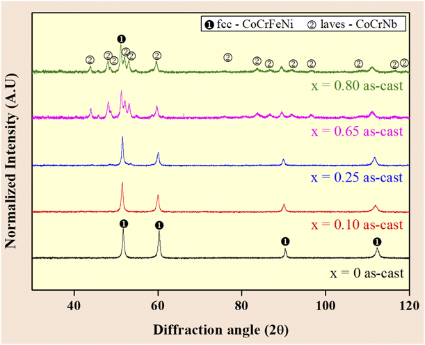
Figure 1 shows the X-ray diffraction (XRD) patterns of the as-cast CoCrFeNiNbx (x = 0 < x < 0.80) alloys. The x = 0 as-cast shows a fcc-CoCrFeNi single phase only. Addition of Nb introduces the hcp-CrCoNb Laves-type brittle phase form as the second phase. However, the peaks of this phase are not intense for the hypoeutectic alloys (x > 0.65). When the Nb content increases to eutectic (x = 0.65) and hypereutectic (x = 0.80) compositions, the intensities of the peaks of the hcp-CrCoNb Laves phases increase significantly, suggesting the increase in the volume fraction of the second phase (Laves-CoCrNb), which is consistent with published reports [Reference Tsai, Fan and Wang20, Reference He, Wang, Zhu, Li, Dang and Wang21, Reference He, Wang, Shang, Leng, Li and Wang22, Reference Maity, Prashanth, Balci, Wang, Jia and Eckert23, Reference Maity, Prashanth, Balci, Kim, Schöberl, Wang and Eckert24].
XRD pattern of as-cast CoCrFeNiNbx (0 < x < 0.80) alloys showing the presence of fcc-CoCrFeNi and hcp-CoCrNb phases as a function of the Nb addition.
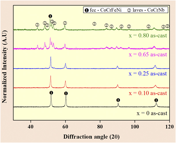
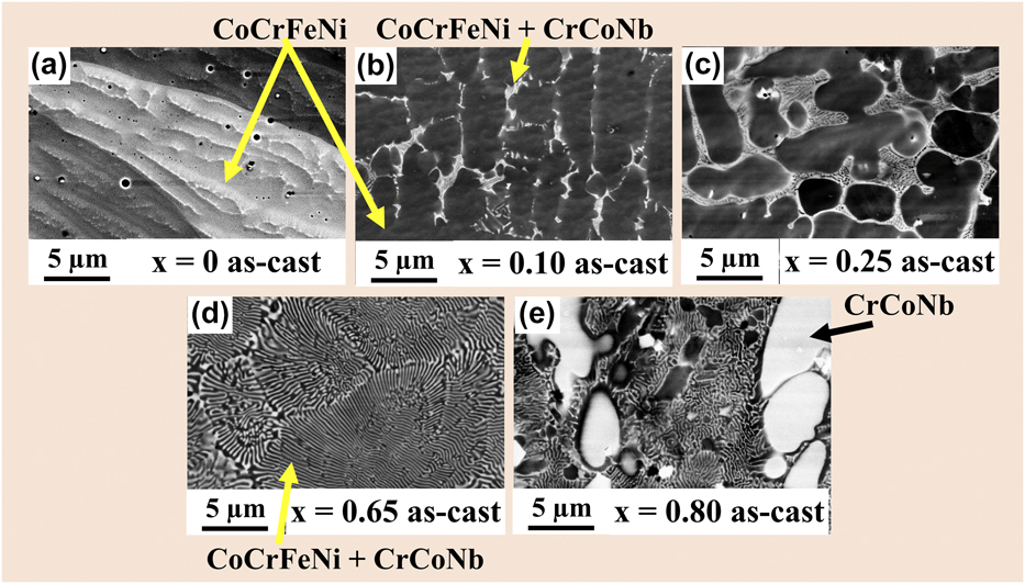
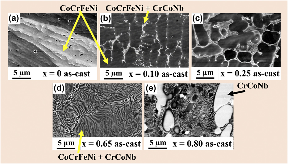
Figure 2 shows the SEM back-scattered electron (BSE) micrographs of the as-cast alloys. The x = 0 as-cast alloys shown in Fig. 2(a) reveal a single-phase (fcc CoCrFeNi solid solution) structure. By contrast, the x = 0.1 as-cast and x = 0.25 as-cast alloys display segments of lamellar eutectic morphology comprising darker fcc CoCrFeNi and brighter hcp CrCoNb Laves phases. The segments of lamellar eutectic morphology, as generated during the solidification, are embedded in the fcc CoCrFeNi solid solution [Figs. 2(b) and 2(c)]. When the Nb content is increased to x = 0.65 molar ratio, a regular complete eutectic morphology is observed, as shown in Fig. 2(d). Further Nb addition up to x = 0.80 molar ratio creates a typical eutectic–dendritic hypereutectic morphology with primary hcp CrCoNb dendrites in a lamellar eutectic matrix, as shown in Fig. 2(e). These findings reveal that Nb addition changes the morphology from an initial single-phase solid solution (x = 0 molar ratio) to a hypoeutectic microstructure (x = 0.1 up to 0.25 molar ratio), then to a eutectic morphology (x = 0.65 molar ratio), and, finally, to a hypereutectic eutectic-dendritic morphology (x = 0.80 molar ratio) [Reference Tsai, Fan and Wang20, Reference He, Wang, Zhu, Li, Dang and Wang21, Reference He, Wang, Shang, Leng, Li and Wang22, Reference Maity, Prashanth, Balci, Wang, Jia and Eckert23, Reference Maity, Prashanth, Balci, Kim, Schöberl, Wang and Eckert24].
SEM BSE micrographs comparing the morphology of as-cast CoCrFeNiNbx (0 < x < 0.80) alloys showing (a) the single-phase fcc CoCrFeNi high-entropy morphology for an x = 0 as-cast sample, fragments of lamellar eutectic morphology embedded in a fcc CoCrFeNi solid solution phase for (b) x = 0.1 and (c) x = 0.25 as-cast samples, respectively; (d) x = 0.65 specimens showing a eutectic morphology with alternating CoCrFeNi//CrCoNb nano-lamellar phase and (e) x = 0.80 as-cast composites showing a bimodal eutectic-dendritic morphology with a high-volume fraction of hard CrCoNb.
Microstructure evolution after HPT
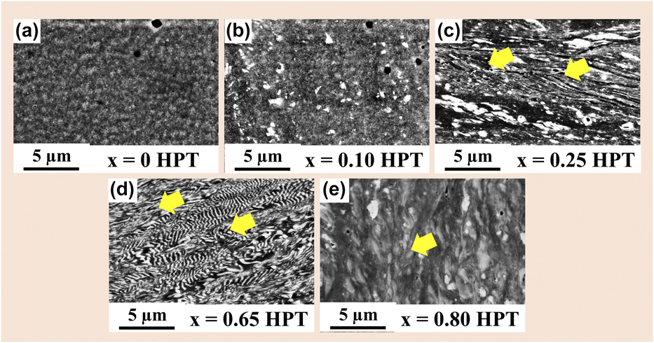
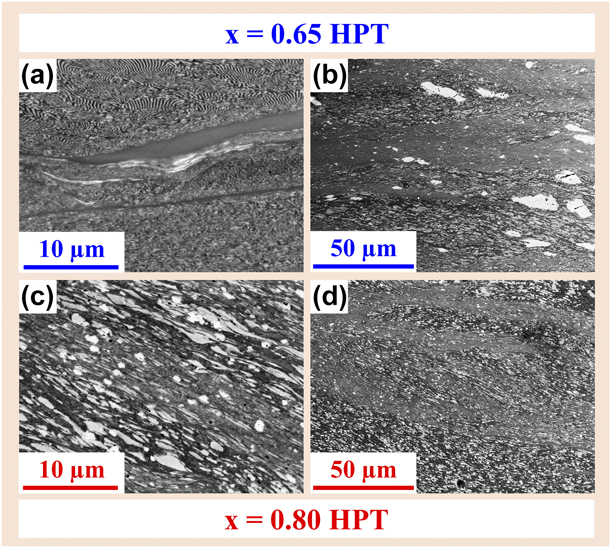
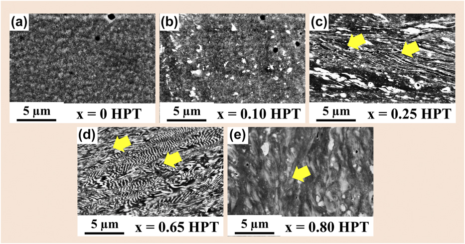
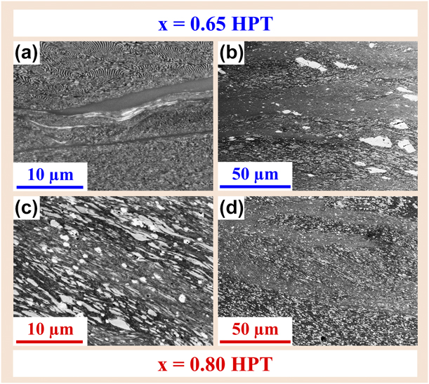
Figure 3 shows SEM BSE micrographs after HPT observed near 3/4th distance from the center to edge of the specimens, where the strain is expected to be maximum. Figure 3(a) shows that the x = 0 HPT HECs undergo nano-structuring upon severe straining, without any significant severe grain flow. In case of the x = 0.1 HPT and x = 0.25 HPT HECs, the lamellar eutectics break and are dispersed homogeneously in the nano-structured fcc solid solution, as evidenced in Figs. 3(b) and 3(c). Figures 3(d) and 3(e) show micrographs of the x = 0.65 HPT and x = 0.80 HPT HECs, exhibiting diffused nano-lamellar interfaces. The x = 0.80 HPT HEC reveals the formation of a bimodal grain-size distribution in the microstructure, with elongated CrCoNb dendrites surrounded by nano-lamellae with an interlamellar spacing (λ) of ∼200 nm. Closer inspection revealed that HPT has transformed the lamellar eutectic microstructure into a homogeneous fibrous morphology along with severely deformed/elongated, diffused, and broken dendrite islands without any visible cracks [Figs. 3(d) and 3(e)]. Furthermore, a homogeneous distribution of sharp and wavy micro-SBs was observed in the microstructure (marked as yellow arrows). The eutectic microstructural features after 30 rotations of HPT show a saturated state, suggesting a limitation in microstructure refinement [Reference Kormut, Ghosh, Bachmaier, Hohenwarter and Pippan45], and the wavy appearance indicates accommodating shear strain during severe straining [Reference Kim, Hong, Park, Eckert and Kim46]. Despite such micro-SBs, Fig. 4 reveals two types of distinct localized ribbon-like SBs (referred as macro-SBs) in the eutectic x = 0.65 HPT and hypereutectic x = 0.80 HPT HECs. Featureless SBs were found in the eutectic x = 0.65 HPT, and fine nano/ultrafine SBs were found in the hypereutectic x = 0.80 HPT HECs. The macro-SBs flow toward the shear direction and show elongated and broken CrCoNb dendrites aligned toward the shear direction. Figure 4(d) reveals the propagation and branching of SBs [Reference Kim, Hong, Park, Eckert and Kim46].
SEM BSE micrographs revealing the morphology of CoCrFeNiNbx (0 < x < 0.80) alloys showing nano-structuring upon HPT for (a) x = 0 HPT, (b) x = 0.1 HPT, and (c) x = 0.25 HPT alloys. Nano-structuring and severe grain flow and breaking of eutectic lamellae are depicted in (d) for an x = 0.65 HPT specimen, and a severely deformed elongated bimodal eutectic-dendritic morphology with diffuse and broken islands of Laves dendrites is shown in (e) x = 0.80 HPT composites: there are no cracks, and the SBs have a wavy appearance.
Distinct localized (a, b) “structureless-type” D-SBs abundant mainly in the x = 0.65 HPT composites and (c, d) finer “nano-/ultrafine-type” T-SBs consisting of finer nanolamellae in the x = 0.80 HPT composites.
Vickers microhardness variations and mechanical property evaluation
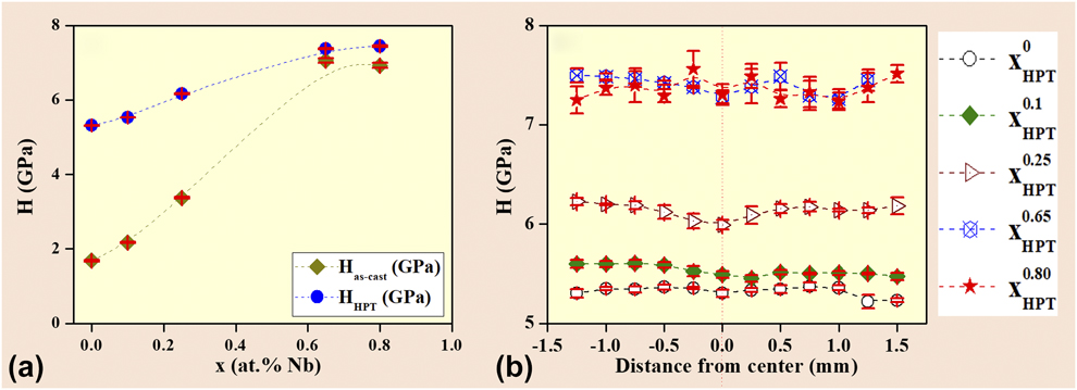
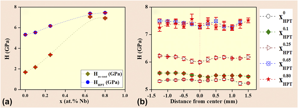
The Vickers hardness (H) values before and after HPT are exhibited in Fig. 5(a). The x = 0 as-cast HEA shows the lowest Vickers microhardness 0 value of H = 1.68 ± 0.02 GPa, whereas a gradual transition from the hypoeutectic to eutectic and hypereutectic regime exhibits a substantial increase in hardness H. The eutectic lamellar x = 0.65 as-cast HECs show the highest Vickers hardness of H = 7.06 ± 0.06 GPa, but the H suddenly decreases to H = 6.92 ± 0.07 GPa for the hypereutectic as-cast x = 0.80 HECs, although they have a large fraction of hard and brittle Laves dendrites. For the HPT-processed HECs, the H values are found to increase continuously from H = 5.31 ± 0.01 GPa (x = 0 HPT HEC) to H = 7.38 ± 0.02 GPa (x = 0.65 HPT eutectic HEC). An increase in Nb beyond the eutectic regime does not show an appreciable increase in the H values, but they remain at a similar plateau (H = 7.44 ± 0.02 GPa for the x = 0.80 HPT HEC). Figure 5(b) depicts the H as a function of distance (y) from the center in the HPT HECs. The measured values of H are similar within the experimental limits as a function of distance y from the center. This suggests that the samples are homogenized after 30 HPT rotations and that the hardness is quite homogeneous throughout the samples without evidence of any strain gradient in the microstructure. Such values are pretty consistent with the earlier works on nanoindentation, where the nanohardness becomes reasonably homogeneous, thereby indicating that microstructural homogenization at the imposed shear strain on the HPT disc is 107 and 147 at the 1/2 and 3/4th distance from center to the edge, respectively [Reference Maity, Prashanth, Balci, Wang, Jia and Eckert23, Reference Maity, Prashanth, Balci, Kim, Schöberl, Wang and Eckert24].
(a) Comparative Vickers microhardness measurements between as-cast specimens and after HPT showing that the Vickers microhardness H increases upon HPT processing after N = 30 rotations compared with the as-cast condition. (b) Vickers microhardness across the disc diameter showing the saturation in Vickers microhardness H, and thereby confirming the existence of saturation hardness/strength.
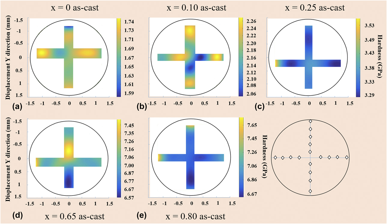
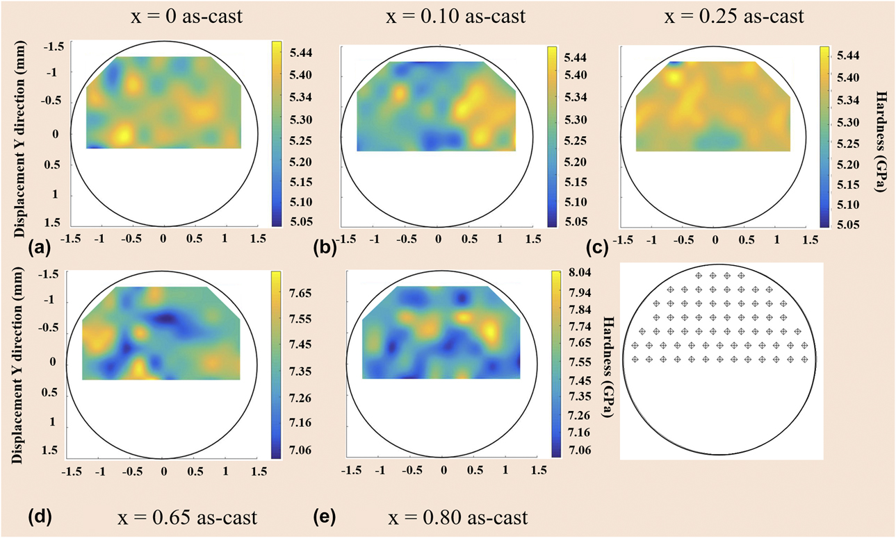
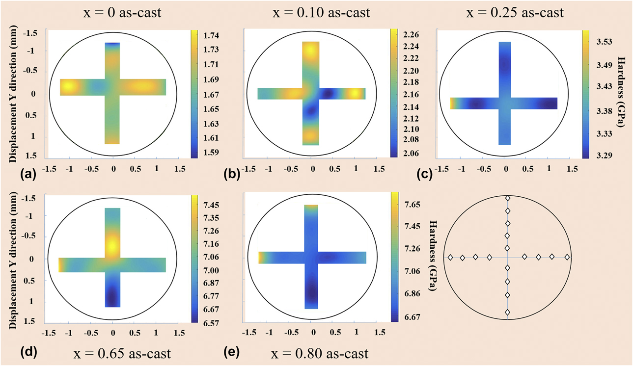
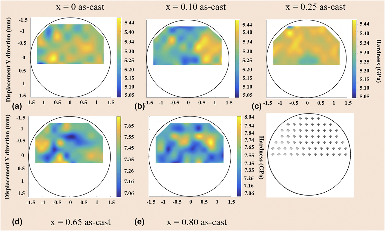
The measured H throughout the microstructures was compared using 2D maps to get an insight into some benchmark estimate of the flow stress σflow. Figures 6 and 7 show the H distribution landscape for the CoCrFeNiNbx alloys in as-cast and HPT conditions, respectively. The hardness maps shown in Figs. 6 and 7 give no hints for a clear hardness segregation that may have been caused by HPT.
Hardness/strength maps for (a) x = 0, (b) x = 0.1, (c) x = 0.25, (d) x = 0.65, and (e) x = 0.80 as-cast alloys.
Hardness/strength maps for (a) x = 0, (b) x = 0.1, (c) x = 0.25, (d) x = 0.65, and (e) x = 0.80 HPT alloys.
Discussion
Effect of HPT on the evolution of wavy micro-SBs
The mechanism of deformation behavior of the HECs was studied using Vickers microhardness. For the x = 0 as-cast HEA, the observed H can be attributed to the solid-solution strengthening, while hardening through the Hall–Petch strengthening becomes the dominant strengthening mechanism after HPT [Reference He, Wang, Zhu, Li, Dang and Wang21, Reference He, Wang, Shang, Leng, Li and Wang22, Reference Maity, Prashanth, Balci, Wang, Jia and Eckert23, Reference Maity, Prashanth, Balci, Kim, Schöberl, Wang and Eckert24]. The Hall–Petch strengthening and the dislocation-induced strain hardening become the dominant deformation mechanisms toward x = 0.65 and x = 0.80 as-cast HECs, where the formation of high area-fraction of eutectic lamellar morphology leads to an increase in hardness and strength [Reference Zhang, Lu, Mickel and Eckert5]. Degradation of the mechanical properties in terms of strength and ductility for the hypereutectic x = 0.80 as-cast HECs can be described as follows. During deformation of the eutectic x = 0.65 as-cast, the alternate soft fcc and hard CoCrFeNi//CrCoNb lamellae strain harden, which improves both the strength and the ductility simultaneously [Reference Zhang, Lu, Mickel and Eckert5]. However, in case of the eutectic x = 0.80 as-cast, the ductile phase yields first upon initial loading/deformation; simultaneously, the hard and brittle CrCoNb dendrites deform elastically and hinder the movement of dislocations, thus improving the flow strength/hardness [Reference Tsai, Fan and Wang20, Reference He, Wang, Zhu, Li, Dang and Wang21]. Because of the increased volume fraction of CrCoNb dendrites in the x = 0.80 as-cast, the dendrite phase breaks and produces cracks. The cracks propagate rapidly, and this results in brittle fracture upon loading.
Effect of severe straining on the lamellar saturation of the lamellar spacing
Figure 4 shows BSE micrographs of the cross-sections of the x = 0.65 and x = 0.80 HPT HECs. The CoCrFeNi//CrCoNb lamellar structures are not as sharp as observed in the as-cast, but they are turned into a dull-fibrous morphology. The microstructural features reveal the existence of wavy micro-SBs. The formation of these micro-SBs results in an increased area fraction of lamellar interfaces (L–I) that accommodate imposed shear strain during severe straining. In the vicinity of the micro-SB boundaries, the L–I become curved to fit the shearing direction and effectively dissipate the shear stress localization.
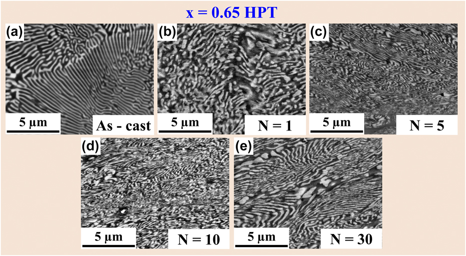
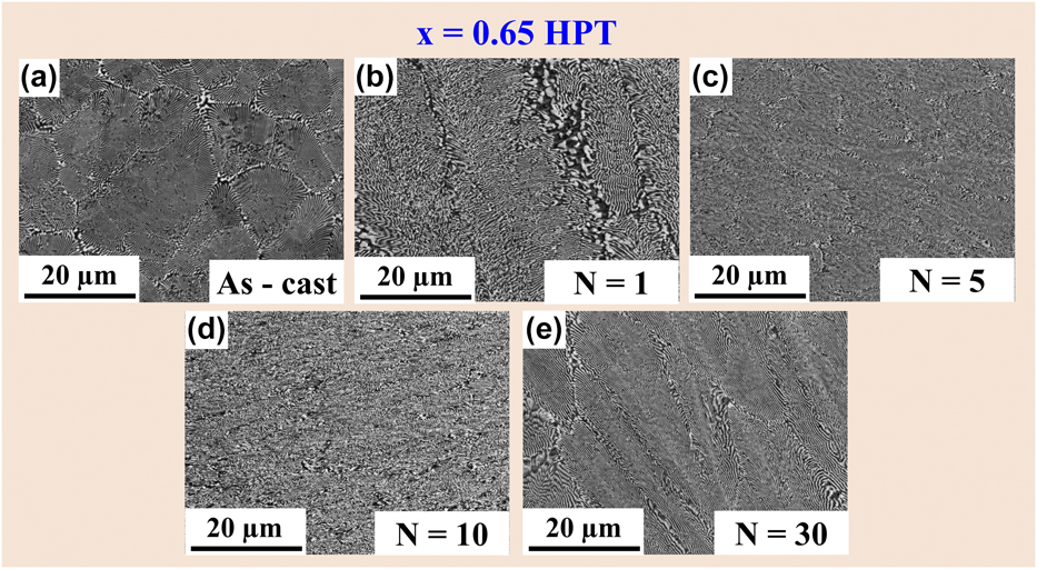
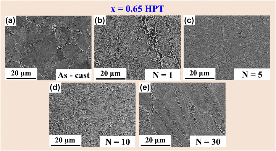
Most importantly, the lamellar eutectic structures become saturated after 30 HPT rotations, as can be seen in Figs. 3 and 4. Similar morphological features were reported for Cu–Ag eutectic alloys, processed by accumulative roll boning (ARB), where the interlamellar spacing saturates after 2 cycles of ARB [Reference Tian, Wu, Zhang, Figueiredo, Gao and Langdon47]. Maity et al. have reported that recovery processes such as lamellar interface boundary migration become highly active through the interaction between dislocations and lamellar interface boundaries during severe straining, as verified by a high strain rate sensitivity (m = 0.09 ± 0.03) and lower activation volume (V* = 2b 3) [Reference Maity, Prashanth, Balci, Wang, Jia and Eckert23, Reference Maity, Prashanth, Balci, Kim, Schöberl, Wang and Eckert24]. Such circumstances activate the deformation-driven grain/lamellae-coarsening mechanisms, which continuously modify the microstructure in a way that further grain/lamellae refinement is impeded when the HECs are severely strained. A further decrease in the size of the lamellar thickness is hindered by higher strains due to microstructural saturation as shown in Fig. 8 [Reference Hafok and Pippan40, Reference Wetscher, Vorhauer and Pippan41]. Figure 8 shows that lamellar microstructure saturation after severe straining through HPT occurs after (i) N = 0 rotations, (ii) N = 1 rotations, (iii) N = 5 rotations, (iv) N = 10 rotations, and (v) N = 30 rotations, respectively. This assures the homogeneous deformation by shear banding and suggests that shear banding is the dominant deformation mechanism when the lamellar spacing becomes saturated upon severe straining [Reference Ding, He, Wang and Yang32, Reference Sasmal, Rahul, Kottada and Phanikumar33, Reference Pollock and Tin34, Reference Dey, Hollang, Beausir, Hieckmann and Skrotzki35, Reference Böhme and Wagner36, Reference Ligda, Schuster and Wei37, Reference Wie, Jia, Ramesh and Ma38, Reference Hebesberger, Stüwe, Vorhauer, Wetscher and Pippan39].
SEM BSE micrographs showing lamellar microstructure saturation after severe straining via HPT at (a) N = 0 rotations, (b) N = 1 rotations, (c) N = 5 rotations, (d) N = 10 rotations, and (e) N = 30 rotations for the x = 0.65 eutectic composition.

Effect of severe straining on the evolution of macro-SBs
Closer inspection of the SEM micrographs reveals micrometer-sized SB-like structures where the lamellar structure disappears completely or partially in the eutectic areas of the x = 0.65 HPT and x = 0.80 HPT HECs, respectively, rather than in the surrounding areas of the microstructure. The macro-SBs contribute strongly to accommodate the applied shear strain [Reference Kormut, Ghosh, Bachmaier, Hohenwarter and Pippan45, Reference Kim, Hong, Park, Eckert and Kim46, Reference Tian, Wu, Zhang, Figueiredo, Gao and Langdon47, Reference Chicot48, Reference Tanaka, Saito, Yasumaru and Hagishida49, Reference Xu, Zhong, Chen, Shen, Liu, Bai and Meyers50]. Such SBs are typical in metallic materials that undergo SPD. The macro-SBs as present in the eutectic dendrite x = 0.80 HPT are referred to as “deformation shear bands” (D-SBs) and in case of the eutectic x = 0.65 HPT HECs as “transformed shear bands” (T-SBs) [Reference Tian, Wu, Zhang, Figueiredo, Gao and Langdon47, Reference Tanaka, Saito, Yasumaru and Hagishida49, Reference Xu, Zhong, Chen, Shen, Liu, Bai and Meyers50]. The formation of such macro-SBs illustrates the formation of “shear banding” as the dominant deformation mechanism. Shear banding is a characteristic unstable deformation mode that has frequently been observed in nanocrystalline materials after severe straining [Reference Xu, Zhong, Chen, Shen, Liu, Bai and Meyers50]. For example, Tanaka et al. reported very similar fine-grained macro-SBs in fully pearlitic steel after wire drawing at RT [Reference Tanaka, Saito, Yasumaru and Hagishida49]. The existence of such SBs implies shear localization in nano-/ultrafine HPT alloys upon severe straining.
In nano-/ultrafine lamellae, localized deformation via shear banding appears at stress concentrations within the lamellae when further lamellar work hardening becomes very difficult due to lamellar thickness saturation [Reference Fan, Wang, Choo, Liaw, Park, Han and Lavernia51, Reference Wright and Ockendon52]. Such new sets of macro-SBs are nucleated to accommodate the imposed plastic strain, thereby causing the lamellae to rotate out of the HPT shear plane with increasing shear strain (HPT rotation N = 0–30), as shown in Fig. 9. Obviously, lamellar colony rotations play an important role, leading to the pronounced ribbon-like macro-SB formation [Reference Dey, Hollang, Beausir, Hieckmann and Skrotzki35, Reference Böhme and Wagner36, Reference Ligda, Schuster and Wei37, Reference Wie, Jia, Ramesh and Ma38, Reference Hebesberger, Stüwe, Vorhauer, Wetscher and Pippan39, Reference Hafok and Pippan40, Reference Wetscher, Vorhauer and Pippan41, Reference Zelin, Krasilnikov, Valiev, Grabski, Yang and Mukherjee42]. The behavior of the HPT eutectic alloys in this work reveals some similarities to nanocrystalline Ta and Fe, to the formation of SBs over time, and to the formation of multiple SBs with increasing strain [Reference Ligda, Schuster and Wei37, Reference Wie, Jia, Ramesh and Ma38]. For the x = 0.80 HPT HECs, the SBs undergo further refinement and destruction of the lamellar structure within the SBs, thus forming D-SBs (Fig. 4). Adiabatic heating during shear banding causes the morphology inside the T-SBs to retain finer lamellae and to retain localization of a large amount of plastic strain within the T-SBs in the x = 0.65 HPT specimens [Reference Tian, Wu, Zhang, Figueiredo, Gao and Langdon47]. The D-SBs are generated via severe shear straining after the generation of the T-SBs, which are abundant in the x = 0.80 HPT [Reference Mayer, Nesterenko, Lasalvia and Xue53]. The temperature increases due to the adiabatic deformation upon HPT inside the SBs; this accelerates further deformation and the lamellar structure breaks down by the rapid progression of shear banding. Such formation of D-SBs implies that the x = 0.80 HPT can accommodate more plastic strain upon severe straining.
SEM BSE micrographs showing lamellar colony rotation in the microstructure after severe straining via HPT at various rotations of (a) N = 0 rotations, (b) N = 1 rotations, (c) N = 5 rotations, (d) N = 10 rotations, and (e) N = 30 rotations in eutectic x = 0.65 HPT alloys.
Underlying mechanism of the strength–ductility trade-off
It has been revealed that severe straining via HPT imparts lamellar thickness saturation in the eutectic and hypereutectic alloys. The lamellar saturation has been further confirmed by the SEM investigation (Figs. 3 and 4) and the hardness/strength maps (Figs. 5–8). Similar microstructural features were reported in severely deformed Cu–Ag eutectic alloys processed by ARB. Very high hydrostatic pressure is responsible for such lamellar spacing saturation via recovery processes such as grain boundary/lamellar interface migration and grain boundary/lamellar interface activity (interaction between the dislocation and grain boundary/lamellar interfaces). The existence of such mechanisms was justified by the verification of high strain rate sensitivity (m ∼ 0.09) and lower activation volume (∼2b 3). Such deformation-driven grain/lamellae-coarsening processes continuously modify the microstructure in a way that further refinement is impeded when the shear strain during severe straining is increased [Reference Kapp, Renk, Leitner, Ghosh, Yang and Pippan54, Reference Pippan, Scheriau, Taylor, Hafok, Hohenwarter and Bachmaier55]. Under such circumstances, i.e., when lamellar structures become saturated, SBs become the major deformation mode, which allows the accommodation of more plastic strain and improves RT plasticity. However, severely deformed grains along the SBs indicate that the alloy still has high ability for plastic deformation.
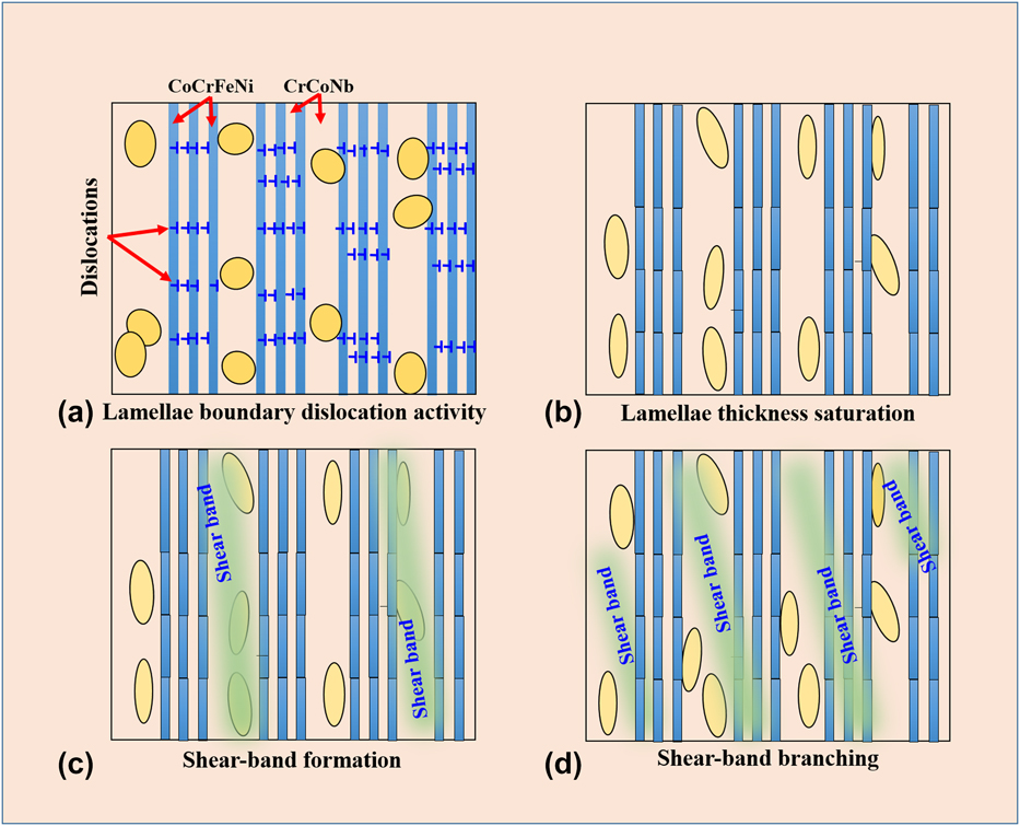
Combining the different findings of this investigation allows to establish a description of the microstructure evolution upon severe straining and to reveal the sequence in the development of shear banding, as illustrated in Fig. 10. During severe straining, dendritic phases break into fragmented particles. These fragmented particles block dislocation motion, thereby improving the strength of the eutectic dendritic x = 0.80 HPT composites. The development of shear banding networking and multiplication of SBs lead to enhanced plasticity. The SB branching effectively distributes the plastic strain associated with shear banding [Reference Kim, Hong, Park, Eckert and Kim46]. Therefore, a large volume fraction of Laves phases in the as-cast specimens renders the alloy hard, but makes it brittle after severe straining at RT. By contrast, the formation of T-SBs, SB branching, and SB multiplication together with a large faction of saturated nano-lamellae accommodate the excessive strain.
Schematic illustration of the evolution of microstructure upon severe straining revealing the sequences in the development of shear banding.

Conclusions
The following conclusions may be drawn from the present work:
(1) Nb addition varies the microstructure from an initial single fcc solid solution to a hypoeutectic, then to a regular eutectic (x = 0.65 as-cast) structure with coexisting lamellar CoCrFeNi//CrCoNb, and finally to a eutectic-dendritic structure (x = 0.80 as-cast) with a large volume fraction of CrCoNb dendrites.
(2) Severe straining by HPT not only increases the Vickers microhardness beyond the values of the as-cast HECs (7.44 ± 0.02 GPa), but also improves hardness saturation and homogeneous hardness/strength distribution.
(3) Severe straining initiates the deformation-driven lamellae-coarsening mechanism that causes lamellar thickness saturation through lamellar boundary migration across lamellar interfaces, continuously modifying the microstructure in a way that further refinement is impeded. This generates easy pathways for the formation of SBs. Such shear banding imparts the late stage of work hardening and becomes the dominant deformation mechanism, thus improving the strength–ductility trade-off.
(4) A high-volume fraction of hard and brittle Laves phases act as both the nucleation site for SBs and the hampering site for the propagation of SBs. This causes SB multiplications, improves strength and plasticity, and prevents catastrophic failure of the material. With further increase in strain, multiple SBs extensively developed throughout the specimens to accommodate the excess strain.
Experimental details
Starting from high-purity (99.99 wt%) elemental Co, Cr, Fe, Ni, and Nb, CoCrFeNi–Nbx HECs (x value in molar ratio, x = 0, 0.1, 0.25, 0.65, and 0.80) were synthesized using a cold copper crucible arc-melter (Edmund Bühler GmbH Arc Melter (AM) from Edmund Bübler, Bodelhausen, Germany) in a Ti-gettered high-purity Ar atmosphere (99.99%). The alloys were remelted several times to achieve chemical homogeneity, and cast into small cylindrical rods of 70 mm length and 3 mm diameter. The as-prepared CoCrFeNi–Nbx alloy ingots were denoted as x = 0 as-cast, x = 0.1 as-cast, x = 0.25 as-cast, x = 0.65 as-cast, and x = 0.80 as-cast, respectively. RT HPT was performed with an applied compressive pressure of ∼7 GPa at a rotation speed of 0.2 rpm at N = 30 rotations [Reference Maity, Prashanth, Balci, Wang, Jia and Eckert23, Reference Maity, Prashanth, Balci, Kim, Schöberl, Wang and Eckert24, Reference Li, Hao, Yi, Chen, Prashanth, Maity and Eckert56]. Besides HPT of 3-mm diameter as-cast HECs (3-mm diameter die chosen for the experiments), 8-mm diameter x = 0.65 at as-cast HECs were also HPT deformed at various rotations of N = 1, 5, 10, and 30 to study the effect of severe straining on microstructure evolution in two-phase eutectic only. Specimens were polished traditionally with abrasive papers to achieve a smooth mirror-like surface. The cross-section surfaces after HPT were prepared using mechanical grinding and polishing using a TegraForce-1 device (Struers, Willich, Germany). 1-μm-sized diamond paste and a colloidal silica suspension were applied at the later polishing stage. A final polishing step by vibro-polishing using Buhler Vibromet 2 (Bübler, Esslingen, Germany) was used to remove surface residual stresses. Structural characterization was done by X-ray diffraction (XRD) using a Smartlab X-ray diffractometer (Rigaku, Neu-Isenburg, Germany) with Cu-Kα radiations (λ = 1.540593 Å), 40 kV voltage, and 40 mA current. The microstructures of the as-cast and the HPT specimens were investigated by using a Zeiss Leo 1525 (Carl Zeiss, Oberkochen, Germany) field emission scanning electron microscope (FESEM) fitted with an energy-dispersive X-ray spectroscopy system (EDX from Oxford Instruments 7426; Oxford Instruments GmbH, Wiesbaden, Germany). Vickers hardness values (H) were measured along the diameter on the surface of the HPT discs using a Buehler Micromet-5100 (Bübler, Esslingen, Germany) Vickers microhardness tester at a maximum load P max of 4.9 N and 15 s holding time. The Vickers indents at the applied P max were large enough to deform a sufficient number of lamellae because a larger indentation depth is more reliable to get an insight into the bulk behavior of the materials [Reference Zhang, Das, Lu, Duhamel, Calin and Eckert3]. To get a first estimate of the strength map, the Vickers microhardness H data were analyzed using the MatLab R2016a (MathWorks, Ismaning, Germany) software. The H data were interpolated via spline interpolation. The mean values may also lead to interesting results, determining a comparable H value for as-cast and HPT specimens.
Acknowledgments
The authors would like to thank Prof. R. Pippan, T. Hohenwarter, P. Kutlesa, and S. Modritsch for their help with high-pressure torsion experiments and metallographic sample preparation, respectively. Financial support was provided through the European Research Council under the ERC Advanced Grant INTELHYB (grant ERC-2013-ADG-340025) and Estonian Research Council under the structural funds MOBERC15.