Introduction
In recent decades, with the advancement of the medical field, painless medical treatment has emerged as a significant area of research. The advancement of gastrointestinal endoscopy technology may have a more significant impact on the assessment of human health. At present, researchers have proposed the wireless capsule endoscope (WCE) as a potential replacement for the traditional endoscope insertion technology.
Implantable antenna is a crucial component of the WCE system. Designing high-performance implantable capsule antennas has become a focal point and a challenge of the wireless biomedical technology research. Generally speaking, capsule antennas must possess the characteristics of miniaturization, wide frequency band, and high gain. To minimize the size of the antenna and create a compact capsule antenna, the authors in references [Reference Alemaryeen1–Reference Zaki, Abouelnaga, Hamad and Elsadek6] employed their distinct research methods to shrink the antenna, thereby allowing room for the integration of other components.
In addition, to enhance the reception of the collected complex image data, the capsule antenna also requires a broader bandwidth. Broadband antennas can effectively mitigate the impact of complex electromagnetic environments on the operational bandwidth. Different methods are used in references [Reference Cui, Liu, Wang, Wang, Zheng and Li7–Reference Li, Li, Du, Sun and Sun10] to expand the antenna bandwidth, which greatly improves the system’s transmission performance. In reference [Reference Cui, Liu, Wang, Wang, Zheng and Li7], a broadband implantable antenna was designed by carving grooves on both the radiator and the ground plane. In reference [Reference Jing, Li, Ding, Shao and Xiao8], Li et al. proposed a broadband circularly polarized implantable antenna that utilizes a stacked parasitic structure to enhance bandwidth. This design not only guaranteed a 3 dBi axial ratio bandwidth of 28.7% but also achieved a −10 dBi impedance bandwidth of 30%. The ultrawideband dual-polarized antenna for the capsule endoscope system was first studied in reference [Reference Li and Guo9]. Dual-polarization was achieved by using a stepped monopole and an irregular rectangular loop antenna, resulting in the proposed antenna having an impedance bandwidth of 2.15–14.75 GHz. In reference [Reference Li, Li, Du, Sun and Sun10], Li et al. proposed obtaining a wide impedance bandwidth for the antenna by exciting dual resonant frequencies.
Moreover, when the capsule endoscope works, the issue of energy transmission becomes a significant area of research. Miah et al. introduced a 1050 kHz efficient wireless power transfer system for active capsule endoscopy [Reference Miah, Jayathurathnage, Icheln, Haneda and Tretyakov11]. The maximum power transfer efficiencies of 20.4% and 17.47% were obtained in the hollow phantom and liquid phantom, respectively. In addition, a hollow receiving coil was proposed in reference [Reference Kuang, Yan and Wang12] to provide sufficient power for the capsule endoscope and minimize the size of the WCE. Experiments have proven that this model is almost unaffected by biological tissue, which ensures the reliable performance of WCE and makes it possible for WCE to be widely used in clinical applications. A wireless power transmission system (WPTS) was proposed in references [Reference Mohammed, Sharif and Neasham13, Reference Sravya, Bobba and Rani14]. Through simulation optimization, the power transmission efficiency and the uniformity of the generated magnetic field have been improved. WPTS can safely and effectively provide power to capsule endoscopes.
Besides, the location information of the capsule endoscope is essential for doctor diagnosis. Algorithms for capsule endoscope positioning systems have been designed in references [Reference Aghanouri, Ghaffari and Serej15–Reference Zhang, Xu, Chen, Dong, Li, Yu, Dong, Liu, Zhuang and Kuang17], resulting in a significant improvement in positioning accuracy compared to previous methods. Recently, a Z-shaped conformal positioning antenna for endoscopic capsules was proposed in reference [Reference Oleksy and Januszkiewicz18]. The proposed antenna technology improved the positioning accuracy by approximately 15%. The geomagnetic positioning technology proposed in reference [Reference Zeising, Thalmayer, Fischer and Kirchner19] is widely used for positioning capsule endoscopes and can accurately track the travel distance of the capsule in the intestine. Its positioning results are significantly better than those of the current state-of-the-art methods for solving capsule endoscope positioning problems.
In this paper, we propose a wireless capsule sensor system that utilizes a three-dimensional single-arm spiral antenna as a transmitting antenna. This design significantly conserves the internal space of the capsule. The system can not only transmit medical data but also diagnose gastric lesions. A three-layer cylindrical model of the stomach was established in HFSS (High Frequency Structure Simulator), and the maximum gain of the antenna working in the stomach was obtained to be −1.1 dBi. The circuit equivalent model is used to determine the sensing characteristics of the entire system. During the actual testing process, solutions with varying dielectric constants are used to verify the sensing characteristics of the capsule endoscope. The maximum transmission distance measured can reach 6.8 m. We also prove the communication stability of the proposed system through the communication link budget. The remaining chapters of this paper are as follows: The “Single-arm spiral antenna design” section introduces the design and optimization of the single-arm spiral antenna, as well as the simulation analysis of the antenna in the stomach model. The circuit design and derivation of sensing characteristics are presented in the “Circuit construction and sensing performance analysis” section. The experimental equipment and measurement results are described in the “Experimental equipment and results” section. The communication link budget is proposed in the “Communication link budget” section. Finally, a conclusion was drawn in the “Conclusion” section.
Single-arm spiral antenna design
Capsule system
The detailed architecture of the entire capsule system is shown in Fig. 1, which consists of an antenna sensor, a voltage controlled oscillator (VCO) oscillator, a battery, a camera, a light source, and a power spacer. Putting these components inside the spiral antenna greatly reduces the overall system volume. To minimize the impact on the human body after swallowing, the entire device is enclosed within the self-healing material proposed in reference [Reference Jayabalakrishnan, Muruga, Bhaskar, Ponnada, Balaji, R, Priya, Deepa, S and P20] with a thickness of 0.1 mm.
Structure diagram of the capsule endoscope system.

Antenna design and optimization
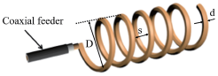
The geometric structure of the designed single-arm spiral antenna is shown in Fig. 2. It is wound with enameled wire ( ${\varepsilon _r} = 1$,
 $\tan \delta = 5.8 \times {10^7}$) in a left-handed manner that has a diameter of 0.5 mm, and its total length is
 $\lambda /2$. A 50-Ω coaxial feeder is added to ensure impedance matching. The most important parameters of the antenna are as follows: D is the diameter of the spiral, s is the distance between adjacent spirals, N is the number of turns, and d is the diameter of the wire. To achieve the best signal transmission effect, we have optimized the antenna by obtaining the best antenna parameters.
The geometric structure of the single-arm spiral antenna.

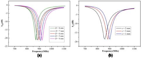
In the pursuit of enhancing three-dimensional spiral antenna performance, as shown in Fig. 3(a), the simulated reflection coefficient (S11) revealed a pivotal relationship between the antenna’s diameter (D) and its resonant frequency. Within the investigated range of spiral diameters from 5 mm to 7 mm, a discernible trend emerged: a decrease in diameter corresponded to an augmented resonant frequency. Upon meticulous analysis, it became evident that the optimal resonant frequency was attainable within this range, precisely at a diameter of 6 mm.
Parameter optimization process diagram. (a) Effect of spiral diameter D on antenna performance, (b) Effect of distance s between adjacent spirals on antenna performance.

The helical pitch (s) of the single-arm spiral antenna will also affect its resonant frequency. While maintaining the total length of the antenna constant, it was observed that increasing the pitch (s) of the antenna resulted in a decrease in the resonant frequency of the spiral antenna. To determine the optimal pitch (s), we simulated the reflection coefficient using pitch (s) of 1 mm, 3 mm, and 5 mm. It can be seen from Fig. 3(b) that to achieve the optimal resonant frequency, the pitch (s) should be between 1 mm and 3 mm. By optimizing within this range, we obtained the optimal pitch (s) of the antenna, which is 2 mm.
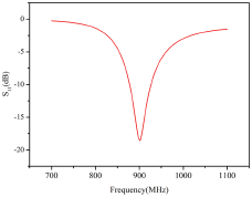
As shown in Fig. 4, the simulated reflection coefficient (S11) of the optimized antenna demonstrates excellent performance at a center frequency of 900 MHz. The return loss is less than −18 dBi, indicating that the antenna reflects very little energy and is therefore highly efficient. In addition, as can be seen from Fig. 4, the −10 dB bandwidth of the antenna is 877–926 MHz, with an impedance bandwidth of 5%. Table 1 shows the parameters of the designed antenna.
Optimized antenna performance.

Parameters of the optimized antenna

To ensure optimal impedance matching for the spiral antenna within the specified operating frequency range, it is important to minimize the imaginary part of its input impedance while keeping the real part close to 50 Ω. This is a crucial element in achieving impedance matching between the antenna and the VCO oscillator. At the center frequency of 900 MHz, its normalized impedance is  $R = 1.1231 + 0.0144{\text{i}}$. This suggests that the impedance of the designed spiral antenna is close to 50 Ω. Therefore, the impedance matching effect between the antenna and the VCO oscillator is good, and most of the energy outputted by the oscillator can be effectively transmitted to the antenna.
Antenna performance analysis in the stomach
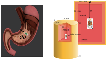
To study the performance of simulated antennas implanted in the human body, we use HFSS software to simulate the stomach, as shown in Fig. 5. We established a gastric model based on the analysis of the human digestive system [Reference Seireg and Abulshohoud21]. The stomach model is constructed from three layers of human tissue: skin, adipose tissue, and stomach lining. Table 2 serves as the foundation for establishing the stomach model.
Three-layer stomach model.

Dielectric properties of different human tissues at 900 MHz

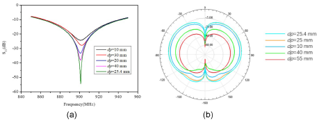
To investigate the impact of implantation depth on the resonant frequency of the simulated spiral antenna, we inserted it into the stomach at depths (dp) of 10 mm, 20 mm, 30 mm, 40 mm, and 50 mm, respectively. The simulated reflection coefficient (S11) of the antenna shown in Fig. 6(a) is obtained. Through observation, we can conclude that the depth of implantation only affects the return loss and does not impact the resonant frequency of the antenna. This resulted in the optimal implantation depth of 25.4 mm, and subsequent experiments were conducted at this depth.
Measurement characteristics of different depths in the stomach. (a) Effect of implantation depth on antenna performance, (b) Radiation gain diagram of YOZ plane at different implantation depths (dp).

Figure 6(b) shows the radiation gain diagram of the YOZ plane when the single-arm spiral antenna is implanted at various depths in the stomach. It can be observed that as the injection depth increases, the antenna radiation gain gradually decreases. At the optimal implantation depth, the simulated antenna can achieve a maximum radiation gain of more than −1.2 dBi on the YOZ plane. This indicates that the antenna maintains a high radiation gain even when implanted in gastric juice.
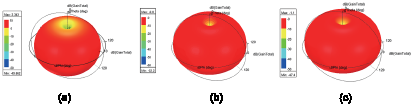
As shown in Fig. 7, the three-dimensional radiation pattern of the simulated antenna is shown under different conditions. When the simulated antenna operates independently, it can be observed that the peak gain reaches 2.243 dBi. When the simulated antenna was implanted in the stomach, the peak gain reached −0.8 dBi. When the analog antenna and VCO oscillator work together in the stomach, the peak gain can reach −1.1 dBi. It shows that the designed antenna has excellent performance in emitting electromagnetic waves.
Simulated radiation gain of the proposed antenna. (a) Antenna in the air, (b) Antenna without VCO oscillator in the stomach, (c) Antenna with VCO oscillator in the stomach.

We employ a 5.8 mm × 6 mm × 0.5 mm PCB board ( ${\varepsilon _r} = 4.6$,
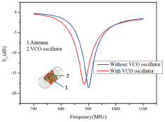
 $\tan \;\;\delta = 1$) to emulate the VCO oscillator, investigating its influence on the resonant frequency of the antenna. In Fig. 8, we present the simulated reflection coefficient (S11) of an antenna implanted in the stomach along with a VCO oscillator. It can be observed that the VCO oscillator has little impact on the resonant frequency of the antenna. We fine-tuned the length of the antenna to ensure that the resonant frequency of the designed antenna is close to 900 MHz after being implanted in the stomach along with the VCO oscillator.
Effect of VCO oscillator on antenna performance.

Circuit construction and sensing performance analysis
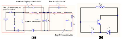
Figure 9(a) shows the detailed circuit diagram of the built capsule endoscope system. Part 1 consists of the system power supply section and VCO oscillator circuit. Part 2 represents the equivalent circuit of the spiral antenna section. The antenna is equivalent to the inductance  $\,{L_1}$. It will create a capacitive effect with other components of the internal environment of the capsule. Its capacitance is equivalent to
 ${C_1}$, and a loss resistance
 ${R_1}$ is also generated. Part 3 is the small capacitance
 ${C_2}$ generated by the contact between the capsule shell and the antenna, and the loss generated through the capsule is
 $\,{R_2}$. Part 4 considers that certain ions in the gastric juice will induce an inductance
 $\,{L_3}$. The capacitance resulting from contact with the capsule and the gastric juice itself is denoted as
 ${C_3}$, while the resistance caused by the gastric juice is recorded as
 ${R_3}$. Part 5 involves the distribution of capacitance
 ${C_4}$, inductance
 ${L_4}$, and resistance R4 generated in the skin, muscle, and fat tissues. It is worth noting here that the capacitance and inductance indicated in the figure are not fixed values and will vary depending on environmental factors.
The equivalent circuit of the capsule endoscope (a) Detailed equivalent circuit, (b) Simplified equivalent circuit.

Figure 9(b) is a simplified equivalent circuit, and the oscillation center frequency of the system can be represented by  ${f_0} = \frac{1}{{2\pi \sqrt {{L_\sum }{C_\sum }} }}$. The capacitance value of the varactor diode C changes as the tuning voltage changes, thereby changing the oscillation center frequency in the oscillation circuit. When the tuning voltage across the varactor diode increases, its capacitance value decreases, causing
 ${C_\Sigma }$ to decrease, which results in the oscillation frequency to increase. On the contrary, when its tuning voltage decreases,
 ${C_\Sigma }$ increases, resulting in a decrease in the oscillation center frequency. Therefore, the oscillation center frequency can be controlled by controlling the tuning voltage across the varactor diode. Due to the influence of external factors,
 ${L_\sum }{C_\sum }$ produces small changes
 $\Delta L$ and
 $\Delta C$, so the change in oscillation frequency is
 \begin{equation}\Delta f = \frac{{\partial {f_0}}}{{\partial L}}\Delta L + \frac{{\partial {f_0}}}{{\partial C}}\Delta C \approx - \frac{1}{2}{f_0}\left( {\frac{{\Delta L}}{L} + \frac{{\Delta C}}{C}} \right)\end{equation}
When the dielectric constant of gastric juice changes, the equivalent impedance  ${L_1}$ of the antenna will change to produce
 $\Delta L$, which will produce a frequency offset
 $\Delta f$, which causes the oscillation center frequency of the entire system to change. Then the dielectric constant of the current gastric juice can be obtained by detecting the offset of the oscillation center frequency to determine whether gastric lesions have occurred.
When a disease occurs in the stomach, the dielectric constant inside it will also change accordingly [Reference Kumar, Mathew, Raveendranath and Augustine22]. The dielectric constant affects the inductance value of the antenna, which will in turn affect the resonant frequency of the antenna. This change can be used to determine whether gastric lesions have occurred by detecting the shift in the center frequency of the signal received at the receiving end. According to the equivalent circuit model of the system, the dielectric constant of the gastric juice directly affects the inductance ( ${L_\Sigma }$), causing a decrease in the resonant frequency of the antenna.
Figure 10 shows the simulated reflection coefficient (S11) of the antenna in gastric juice with a varying dielectric constant (30–80). It can be observed that the resonant frequency of the antenna changes in response to variations in the dielectric constant of the stomach liquid. Therefore, this feature can be used to determine whether there is an abnormality in the stomach.
Effects of different dielectric constants ${\boldsymbol{\,}}{{\boldsymbol{\varepsilon }}_{{\boldsymbol{r\,}}}}$on antenna performance.

Experimental equipment and results
Figure 11(c) shows the proposed capsule endoscope system. To verify its functionality, by inserting the prepared capsule endoscope into the stomach of a pig, we conducted experiments. First, the radiation pattern of our capsule endoscope was measured in a dark room. When the entire system is operational, the half-wavelength Yagi antenna is utilized as the receiving component, while the 4051A spectrum analyzer is employed to monitor the frequency and intensity of signals received from solutions with varying dielectric constants in the stomach. Finally, we utilize a vector network analyzer to measure the actual reflection coefficient of the antenna (S11).
Experimental setup. (a) Experimental equipment for measuring antenna performance, (b)Experimental device for measuring maximum transmission distance and sensing performance, (c) Capsule sensor physical picture, (d) Measuring radiation patterns in the anechoic chamber.

Water, with a dielectric constant of about 78.5 (25°C), and ethanol solution, with a dielectric constant of about 24.3 (25°C), are mixed in specific proportions to create solutions with varying dielectric constants. The dielectric constant of the mixed solution can be expressed as follows.
 \begin{equation}{\varepsilon _{{\text{mixture}}}} = 78.5{\varepsilon _1} + 24.3{\varepsilon _2}\end{equation}
where  ${\varepsilon _1}$ represents the volume fraction of water and
 ${\varepsilon _2}$ represents the volume fraction of ethanol, with the condition that
 ${\varepsilon _1} + {\varepsilon _2} = 1$. We prepared solutions with different dielectric constants and placed them in the stomachs of pigs for experiments.
Under normal operation of the system, the signal frequency emitted by the capsule endoscope was measured when different dielectric constant solutions were present in the stomach. As shown in the spectrum diagram in Fig. 12(b), it is evident that the resonant frequency of the entire system will vary with different dielectric constants of the solution. This observation validates the sensing capability of our system. As shown in Fig. 12(c), the sensing capability can be expressed as  ${\varepsilon _r} = - 2.619{f_0} + 2421.33$,
 ${R^2} = 0.998$.
Experimental results. (a) Actual and simulated antenna performance in the stomach, (b) Spectrum measured with solutions of different dielectric constants in the stomach, (c) Linear fitting of the sensing performance, (d) Diagram of the relationship between received signal strength and distance.

Figure 12(a) shows the S11 curve that was measured and simulated in the pig stomach. During the actual measurement, the obtained antenna resonant frequency is 900.43 MHz, and the −10 dB bandwidth is consistent with the simulated results in the stomach simulation. Due to differences in the production process and materials, there may be some deviations between the actual product and the simulation. However, the actual test results meet our expectations.
According to the trend shown in Fig. 12(d), as the communication distance (dt) increases, the received signal strength gradually weakens. This is attributed to the increase in free space propagation loss resulting from the extended communication distance. To ensure that the signal can be demodulated properly, it is necessary to maintain a signal-to-noise ratio (SNR) of over 14 dB. Given that the environmental noise level is approximately 55 dB, the minimum acceptable signal strength should be −41 dB. Therefore, considering the worst-case scenario, the expected maximum reliable receiving distance is 6.8 m. This distance represents the maximum communication range achievable while preserving the SNR and accounting for environmental noise levels.
To precisely control the oscillator, we tested its performance in free space (25°C) and a pig stomach (36°C). Since batteries typically provide a voltage of 3.7 V, we have configured the input voltage (VCC) of the oscillator to 3.7 V. We obtained two important charts: Fig. 13(a) displays the curve of the VCO oscillator controlling resonant frequency through tuning voltage, while Fig. 13(b) illustrates the influence of tuning voltage on power output. It was observed that when the tuning voltage was 3 V, the output frequency of the oscillator reached 900 MHz. Based on this result, we have determined that the optimal tuning voltage is 3 V. Figure 13(b) reveals that the output power of the oscillator is 5 dBm when the tuning voltage is 3 V.
Oscillator performance testing. (a) The relationship between turning voltage and output frequency, (b) The relationship between turning voltage and power.

Spiral antennas generate electromagnetic radiation during operation. When the spiral antenna enters the human body, the human tissue will absorb a certain amount of electromagnetic radiation. To ensure that human tissues do not absorb excessive amounts of electromagnetic radiation and disrupt the normal physiological characteristics of the human body, IEEE and the International Committee on Non-Ionizing Radiation Protection have developed a set of guidelines for limiting electromagnetic field exposure. One of the key parameters is the specific absorption rate (SAR), which is W/kg. According to the human SAR standard [Reference Bailey, Bodemann, Bushberg, Chou, Cleveland, Faraone, Foster, Gettman, Graf, Harrington, Hirata, Kavet, Keshvari, Klauenberg, Legros, Maxson, Osepchuk, Reilly, Tell, Thansandote, Yamazaki, Ziskin, Zollman and Electromagnetic23], the SAR value should not exceed 1.6 W/kg under the 1-g tissue standard. As shown in Fig. 14(a), when the input power is 1 W, the antenna’s maximum SAR distribution in the gastric tissue is 0.1203 W/kg. Since the output power of the VCO oscillator is 3.162 mW, as shown in Fig. 14(b), the simulation results indicate that the maximum SAR value is 0.0108 W/kg when the input power is also 3.162 mW. This demonstrates that our designed antenna meets the SAR value requirements, even when the input power varies significantly.
SAR of the proposed antenna sensor. (a) With 1 W input power, (b) With 3.162 mW input power.

Table 3 compares the performance of this antenna with other antennas in terms of volume, gain, sensing function, and maximum transmission distance. The spiral-shaped antenna we proposed fully uses the capsule space, and the maximum gain after implantation can reach −1.1 dBi. In addition, our system also has sensing capabilities, with a maximum transmission distance of up to 6.8 m.
Comparison with other implantable antennas

As shown in Fig. 15, the simulated and actual test radiation patterns of the proposed antenna are presented at the E-plane and H-plane at 900 MHz. There is a slight deviation between the actual measured and simulated values. This is due to some environmental factors during the actual testing process, resulting in a slightly smaller radiation gain.
Radiation patterns in different planes. (a) E-plane, (b) H-plane.

Communication link budget
To guarantee the quality, stability, and reliability of signals during transmission, and to ensure that signals can be accurately transmitted and decoded within the expected distance, link budget analysis is crucial [Reference Basir, Zada, Cho and Yoo24, Reference Miah, Khan, Icheln, Haneda and Takizawa28]. In Fig. 16, the proposed antenna is utilized as a transmitting antenna, while the Yagi antenna is employed as a receiving antenna. In the IEEE 802.15.6 standard [Reference Astrin29], it is specified that a 14 dB SNR must be maintained in the 877–926 MHz frequency band.
Schematic diagram of link budget analysis.

Under far-field conditions, SNR can be calculated using the following formula:
 \begin{equation}\Gamma = {\operatorname{P} _r} - N - M - {L_I}\end{equation}
 \begin{equation}{P_r} = {P_t} + {G_t} + {G_r} - {L_{FS}} - {L_u}\end{equation}
 \begin{equation}{L_{FS}} = 10\log 10{(\frac{{4\pi d}}{{\lambda 0}})^2}\end{equation}
 \begin{equation}N = kT \times BW \times NF\end{equation}
where Pr is the received power, N is the noise level, M is the fading margin, LI is the installation loss, Pt is the oscillator output power, Gt is the transmitting antenna gain, Gr is the receiving antenna gain, LFS is the free space path transmission loss, Lu is other potential losses, and dt is the transmission distance. Additionally, λ is the wavelength of the signal, k is the Boltzmann constant, T is the temperature of the system, BW is the bandwidth, and NF is the noise coefficient.
Please note that formula (5) only considers the propagation characteristics in free space. The free space transmission model assumes signal transmission in unobstructed and free space, without accounting for the effects of multipath fading, terrain, obstacles, and other factors on signal propagation.
Considering that the output power (Pt) of the oscillator in our proposed system is 5dBm, the gain (Gt) of the transmitting antenna is −1.1 dBi, and the gain (Gr) of the receiving antenna is 2.12 dBi, with unknown loss (Lu) equal to 0. In free space, with a center frequency of 900 MHz and a distance of 6 m, the transmission loss (LFS) of the free space path can be calculated as 38.53 dB. Please note that the unknown loss Lu does not include the free space path transmission loss (LFS). The power received by the receiving end can be calculated as Pr = −32.61 dBi. A receiver with a noise figure of 10 dB as the reference has a total noise power of N = −102.14 dBm. Even after considering the fading margin (M = 20 dB) and installation loss (LI = 11 dB), our SNR remains at 38.63 dB, which exceeds the required SNR by 24.63 dB. This indicates that our system still has 24.63 dB of fault tolerance space for other potential losses, ensuring the reliability of our system’s communication. The data for the link budget is presented in Table 4. As a result, the system we propose has robustness.
Parameters of the link margin calculation

Conclusion
This study proposes a capsule endoscopy system for medical applications that utilizes a three-dimensional spiral antenna to maximize the use of space within the capsule. Capsule endoscopes not only have sensing functions but also have smaller sizes. Through equivalent circuit analysis, it has been concluded that the system possesses sensing capabilities. Experiments have been conducted to confirm its sensing function and determine the maximum transmission distance achieved. In summary, the capsule endoscopy system used in this study has significant potential value in medical applications. The link budget statement confirms its communication capability. It can be utilized to detect gastric diseases and enhance the accuracy and convenience of medical diagnosis.
Acknowledgements
This work was supported by the National Natural Science Foundation of China (No. 62341123). We appreciate the editor’s and reviewers’ valuable comments and suggestions for our manuscript.

Xiangyuan Nan is currently pursuing a Bachelor’s degree in Integrated Circuit Design and Integrated Systems at Tianjin University of Technology in Tianjin, China. His research interests include integrated circuit design, antenna design, and implantable microwave devices.

Daolian Jiang obtained a Master’s degree in Information and Communication Systems Engineering from Tianjin University in 2008. He is a lecturer at Tianjin University of Technology and the director of Tianjin Experimental Teaching Demonstration Center. His research areas include radio frequency electronic technology theory, electronic technology applications, and information and signal processing.

Xiu-Wei Xuan received the M.S. degree in signal and information processing and the Ph.D. degree in information and communication engineering from Tianjin University, Tianjin, in 2009 and 2012, respectively. She is now an associate professor in Tianjin University of Technology, China. Dr. Xuan is also a member of Tianjin Key Laboratory of Film Electronic and Communication Device. Her research interests include antenna design, antenna sensor theory, implantable and wearable microwave devices.

Jiajia Xie is currently pursuing a bachelor’s degree at Kashgar University in Xinjiang, China. Her research interests include wireless communication and circuit design.

Yiwei Hu is currently pursuing communication engineering at Tianjin University of Technology, Tianjin, China. Her research interests include development and design of mobile communication.

Xingqi Liu is currently pursuing a bachelor’s degree in communication engineering at Tianjin University of Technology, Tianjin, China. Her research interests include microcontroller development and design.