I. INTRODUCTION
The next generation gas turbine engines will employ advanced materials that are specifically designed to handle the harsh environment inside the hot section of an engine. Thus, there is a need to develop instrumentation that can survive the higher operating temperatures associated with these advanced engine designs and monitor the conditions during operation. Specifically, engine components based on ceramic matrix composites or CMC’s are lighter and have superior thermo–mechanical properties compared to nickel-based superalloys. Reference Tougas, Amani and Gregory1 Thus, they can operate at higher temperatures, which enable greater overall efficiencies. Advanced instrumentation must not only survive the rotational forces and high temperatures but must also be capable of accurately monitoring the temperature and strain of CMC engine components. Given the harsh conditions inside the gas turbine engine, it is becoming increasingly more difficult to instrument these CMC engine components to monitor structural integrity for extended periods of time, without adversely affecting operation of the engine.
Wire thermocouples, for example, are difficult to use on CMC’s for temperature measurement, since they cannot be easily incorporated into the surfaces of environmental barrier coatings without affecting gas flow over the surface. Reference Tougas, Amani and Gregory1 Typically, thin film sensors are deposited directly onto the surface of a component so that a true surface measurement is possible. In this way, thin film instrumentation becomes an integral part of the surface of a component. Thin films sensors have several advantages over conventional wire thermocouples. They do not interfere with gas flow paths through the engine because they have a low profile; i.e., they have thicknesses on the order of micrometers, which is well below the boundary layer thickness. Thin film sensors have extremely small masses (on the order of 10−6 g). With a minimal mass, this means that thin film sensors will not alter the vibrational modes of blades comprising the turbine. It also translates into faster response times Reference Tougas, Amani and Gregory1 and there is no need for adhesives. However, thin film sensors also have some disadvantages including relatively small diffusion distances, which can lead to decreased stability at elevated temperature.
Recent research has focused on developing thin film temperature and strain sensors for the next generation of ceramic matrix composites. Reference Tougas, Amani and Gregory1,Reference Wrbanek, Fralick and Zhu2 Much of this research has focused on platinum and palladium thin film thermocouples but these suffer from limitations associated with oxidation of the palladium at elevated temperatures. Reference Tougas and Gregory3 Thin film thermocouples utilizing the SiC–SiC CMC itself as one of the thermoelements and platinum as the other thermoelement were fabricated on SiC–SiC CMC’s and evaluated in terms of thermoelectric performance. Here, the bulk properties of SiC determine sensor performance (thermoelectric response) as opposed to the thin film properties of materials such as platinum and palladium. The Pt:SiC CMC thermocouples exhibit thermoelectric powers ranging from 130 μV/K to 250 μV/K depending on how the thermocouple is oriented with respect to the SiC fibers or weave in the CMC. These thermocouples can operate at significantly higher temperatures in the harsh environment of the gas turbine engine while maintaining low drift at temperature.
At high temperatures, the Pt:SiC interface comprising the hot junction of the Pt:SiC CMC thermocouple can undergo oxidation; i.e., oxygen can diffuse through the platinum film and react with the SiC to form an SiO2 layer. This oxide changes the nature of the ohmic contact associated with the Pt:SiC junction and produces a rectifying junction, which ultimately contributes to the measured electromotive force (emf). This can lead to considerable signal drift that increases with increasing temperature. Thus, implementing an effective oxygen diffusion barrier is critical to the high temperature performance of these Pt:SiC CMC thermocouples. Increased stability at high temperatures is a priority of this research since most thin film sensors fail due to the small diffusional distances associated with these devices. Bulk properties of the SiC in the CMC make Pt:SiC CMC thermocouples promising candidates for the extreme environments anticipated in advanced gas turbine engines. These thermocouples are also extremely sensitive, having a maximum thermoelectric voltage almost two orders of magnitude greater than those generated with type K wire thermocouples. 4–10 Yet the drift rates associated with these thermocouples were significantly lower than other types of thin film thermocouples. However, the hot junctions can also undergo platinum-silicide formation at temperatures greater than 600 °C. The formation of platinum-silicides is normally inhibited by the diffusion of oxygen through the platinum Reference Nicolet11 but when an oxygen diffusion barrier is used, the thermodynamics shift in favor of the formation of platinum-silicides in the absence of oxygen at the Pt:SiC junction. At high temperatures (∼1100 °C), a mixture of silicides are produced, Reference Chou12–Reference Tanner and Okamoto14 but no carbides were formed since carbon precipitates migrate to the platinum-silicide grain boundaries. Reference Chou12,Reference Rijnders, Kodentsov, Van Beek, van den Akker and van Loo15 Thus, a platinum-silicide diffusion barrier is necessary if these Pt:SiC (CMC) thermocouples are to be utilized for very high temperature applications.
The silicon-carbide fiber-reinforced silicon-carbide (SiC/SiC) composites were supplied by the NASA Glenn Research Center and are typically used for high temperature, structural applications. These fiber-reinforced materials show significantly improved toughness and damage tolerance in comparison to unreinforced monolithic ceramic materials with similar matrix compositions. Reference DiCarlo and Yun16,Reference DiCarlo and Yun17 Other materials have been considered for these applications including: metallic super alloys, carbon fiber composites, and oxide/oxide ceramic composites. For successful application, the ceramic matrix composite properties must be reproducible when fabricated in 3D shapes and maintain their strength at temperatures up to 1400 °C. Sylramic-iBN fibers (10-μm in diameter). These were processed via chemical vapor infiltration (CVI) of commercial Sylramic SiC. Reference DiCarlo and Yun16,Reference DiCarlo and Yun17 These fibers are dense, polycrystalline, and exhibit stoichiometric ratios of Si and C. They also contain approximately 1% boron and 3% TIB2 by weight. Reference DiCarlo and Yun16,Reference DiCarlo and Yun17 The fibers are treated by the CVI of boron nitride (BN), which allows excess boron in the bulk to diffuse to the fiber surface. Reference DiCarlo and Yun17 It then reacts with nitrogen to form an in situ BN coating on the fiber surface improving creep resistance and thermal conductivity. Reference DiCarlo and Yun17 The BN coating also aids in increasing the oxidation resistance of the CMC at higher temperatures. Reference Naslain18 Coating the fibers provide matrix crack deflection and also prevents the growth of silica on fiber surfaces at high temperatures. Reference DiCarlo and Yun16,Reference DiCarlo and Yun17 Undesired silica growth allows for strong mechanical bonds to form between the contacting fibers causing fracture or rupture stresses to be much lower than independently acting fibers. Reference DiCarlo and Yun16,Reference DiCarlo and Yun17 SiC CMC’s are also highly fatigue resistant Reference Naslain18 making them a much more attractive option for high temperature applications.
II. EXPERIMENTAL SECTION
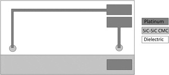
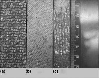
A schematic of a Pt:SiC CMC thermocouple (top view) is shown in Fig. 1. The thermocouple is comprised of a SiC–SiC CMC substrate that is coated with mullite or other dielectric for device isolation and two Pt:SiC junctions. In Fig. 1, the light gray areas represent the CMC material while the dark gray areas represent the platinum bond pads and interconnects. The SiC–SiC (CMC) beams measured 1 × 7 inches. Three different weave orientations were utilized for the thermoelectric experiments. Specifically, the SiC–SiC CMC beams had weaves parallel to, perpendicular to and at a 45° angle with respect to the long axis of the CMC beams, as shown in Fig. 2. A mullite coating or other dielectric, approximately 200 μm thick was applied to the surface of the CMC and heat treated at 100 °C for 20 min, at 200 °C for 20 min and at 300 °C for 40 min followed by a 1000 °C heat treatment for 10 h in a Deltech furnace. A dry negative MX5050™ DuPont™ photoresist (DuPont Electronic Technologies, Durham, North Carolina) was applied to the surface of the dielectric-coated beam and soft baked at 100 °C for 1 min to pattern with thin film portion of the sensors.
Schematic of a Pt:SiC CMC thermocouple, showing location of bond pads and interconnects (top view). Gray areas represent the CMC material while the dark gray represents the platinum bond pads and interconnects.

Photograph of three SiC–SiC CMC’s beams used for the thermoelectric experiments. The SiC weaves in the CMC were (a) parallel to, (b) at a 45° angle to and (c) perpendicular to the long axis of the CMC beams.

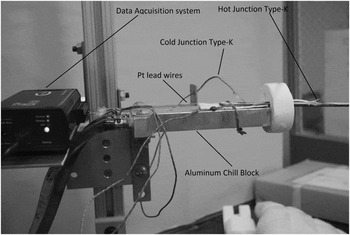
The photoresist-coated substrate was then exposed to ultraviolet light source (350 nm) using an AOI Aligner and developed using an ammonium hydroxide based developer. The SiC–SiC CMC substrates were pre-etched using buffered HF to remove any native oxide layer that had formed on the surface during previous heating steps. Radio frequency (rf) sputtering was used to deposit platinum thin film interconnects and bond pads onto the surface of the SiC–SiC CMC substrates (Fig. 1). A chamber background pressure of 9 × 10⁻³ mTorr was maintained prior to sputter deposition. An rf power of 250 W was used to deposit the platinum thin films. All platinum films were sputtered for 2 h, resulting in a thickness of 1.5 μm. The furnace was programmed as follows: ramp to 700 °C at a rate of 4 °C/min and hold period of 30 min, a ramp to 200 °C at a rate of 4 °C/min and hold period of 30 min, a ramp back up to 700 °C at a rate of 4 °C/min and a hold period of 300 min, and finally a ramp back down to room temperature at a rate of 4 °C/min. This protocol was used to determine the thermoelectric voltage as a function of temperature difference between the hot and cold junctions of the thermocouple. Drift was measured as a function of time while the furnace was held at a constant hot junction temperature. The test bed used for thermoelectric characterization is shown in Fig. 3. Here, the SiC–SiC CMC beam was cantilever loaded to a chill block that uses ethylene glycol or chilled water to keep the block temperature at or near room temperature, while the hot junction temperature was varied from 100 to 1000 °C. Platinum wires were used to connect the thermocouple to the PDaq data acquisition system. Two type-K thermocouples were used to monitor the hot and cold junction temperatures on the instrumented SiC–SiC CMC beam, which was attached to the aluminum chill block (Fig. 3). The assembly including the chill block was inserted into a horizontal tube furnace, with the heat shield producing a temperature gradient along the beam. The thermoelectric voltage, V t, was measured as a function of temperature according to Eq. (1) below:
 $${V_{\rm{t}}} = {{\Delta V} \over {\Delta T}}\quad ,$$
where ∆V is the voltage difference between the SiC–SiC CMC and platinum and ∆T is the difference between the hot and cold junction temperatures. Drift rate, r, was also measured at temperature for the Pt:SiC CMC thermocouples, according to Eq. (2) below:
 $$r = {{\Delta V} \over {{V_{\rm{i}}}}} \cdot {{{T_{\rm{c}}}} \over {\Delta t}}\quad ,$$
where ∆V is the voltage difference measured at a constant temperature (T c), V i is the initial voltage measured and ∆t is the time interval over which the voltage changes. Drift typically occurs due to the formation of an oxide layer between the platinum and SiC as a result of oxygen diffusion through the platinum interconnect. when the Pt:SiC (CMC) thermocouple that does not utilize an oxygen diffusion barrier. Drift could also be attributed to the formation of platinum-silicides of a Pt:SiC (CMC) thermocouple with an oxygen diffusion barrier but not a platinum-silicide barrier.
Photograph of test bed used for thermoelectric testing. CMC beam is cantilever loaded to a chill block that keeps the cold junction at or near room temperature, while the hot junction temperature was varied from 100 to 1000 °C. The heat shield produces a temperature gradient along the CMC beam.

III. RESULTS AND DISCUSSION
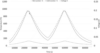
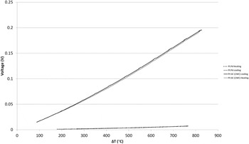
Figure 4 shows the thermoelectric response of a Pt:SiC CMC thermocouple as a function of temperature, with a peak hot junction temperature of 925 °C. While the cold junction temperature varied from 25 to 100 °C. The fiber orientation used in this test is the same as shown in Fig. 2(c) and a maximum voltage of 190 mV was observed for a peak temperature of 925 °C. The thermoelectric response of the same Pt:SiC CMC thermocouple relative to a platinum:palladium thin film thermocouple is shown in Fig. 5. Here, the hysteresis upon heating and cooling (Fig. 5) is minimal for the Pt:SiC CMC thermocouple as well as the platinum:palladium thin film thermocouple. The large difference in the slopes of the two curves is related to the difference in thermoelectric power for the two thermocouples. While both maintain very low hysteresis, the thermoelectric power of the Pt:SiC CMC thermocouple is almost two orders of magnitude greater than that of the platinum:palladium thermocouple due to the contribution of SiC–SiC CMC bulk properties to the thermoelectric power.
Thermoelectric response of a Pt:SiC CMC thermocouple fabricated onto a SiC–SiC CMC substrate with fibers parallel to the long axis and tested for 20 h. A peak hot junction temperature of 925 °C was achieved.

Thermoelectric response of a Pt:SiC CMC thermocouple and platinum:palladium thin film thermocouple upon heating and cooling; note the large difference in slopes for the two different thermocouples. There is almost no hysteresis between heating/cooling. Data for the Pt:SiC CMC thermocouple were taken from the cycles shown in Fig. 4.

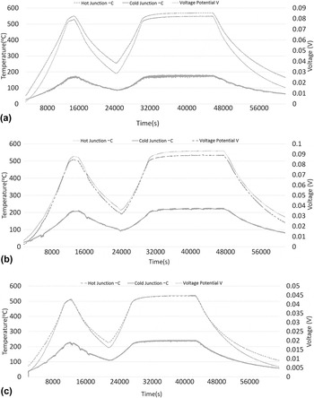
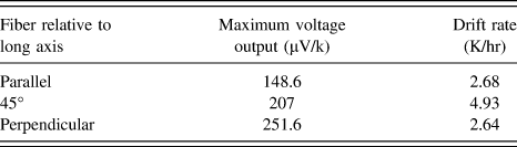
Thermoelectric response of Pt:SiC CMC thermocouples having different SiC fiber weaves is shown in Figs. 6 and 7. The weave directions were parallel to, perpendicular to, and at a 45° angle relative to the long axis of the CMC beams as shown in Fig. 2(b). The Pt:SiC CMC thermocouples here did not have the benefit of an oxygen diffusion barrier. When the CMC beams had SiC fibers perpendicular to the long axis of the beam, a maximum thermoelectric power of 148 μV/°K was realized when the hot junction reached a temperature of 510 °C, which was the smallest response of all fiber orientations but still much larger than any response generated by Pt:Pd thermocouples (∼12 μV/K). Reference Tougas and Gregory3 The drift rate at this temperature was 2.68 °C/h, which is extremely low when compared to most thin film thermocouples. When the CMC substrate had a 45° diagonal SiC fiber weave relative to the long axis of the CMC beam, a maximum thermoelectric power of 207 μV/°K was realized when the hot junction reached a temperature of 510 °C. The drift rate at this temperature was 4.93 °C/h, which was the highest among all the substrates tested. When the CMC substrate had a parallel SiC fiber weave relative to the long axis of the CMC beam, a maximum thermoelectric power of 251 μV/°K was realized when the hot junction reached a temperature of 530 °C. The drift rate at this temperature was 2.64 °C/h, which was the lowest seen among all the substrates tested. Therefore, the orientation with the largest thermoelectric power was the CMC beam with a SiC fiber weave parallel to the long axis of the CMC beam. The results shown in Fig. 6 suggests that fiber orientation had a major effect on thermoelectric properties and that the SiC fibers played a large role than the SiC matrix in determining the overall thermoelectric properties. If the SiC matrix contributed to a greater extent than the SiC fibers, there would not be a strong correlation between the SiC fiber orientation and overall thermoelectric properties. Wrbanek et al. showed that conductive oxides produce much greater thermoelectric powers Reference Wrbanek, Fralick and Zhu2 than the Pt:SiC CMC thermocouple but the thermocouples described within rely on bulk properties of the substrate material itself.
(a) Thermoelectric response of a Pt:SiC CMC thermocouple with a SiC fiber weave that was at 45° diagonal relative to the long axis of the CMC beam, (b) Thermoelectric response of a Pt:SiC CMC thermocouple with a parallel SiC fiber weave relative to the long axis, and (c) Thermoelectric response of a Pt:SiC CMC thermocouple with a perpendicular SiC fiber weave relative to the long axis of the CMC beam.

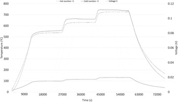
Thermoelectric response of a Pt:SiC CMC thermocouple at 530, 630, and 730 °C fabricated with an ITON diffusion barrier.

The thermoelectric responses for the various SiC fiber orientations proved to be very stable as evidenced by the low drift rates observed for these thermocouples relative to thin film thermocouples. Although the temperatures were intentionally kept relatively low, the drift in the thermoelectric response of these Pt:SiC CMC thermocouples was likely due to oxidation to some extent via oxygen diffusion through the platinum interconnect thin film. Oxidation at the Pt:SiC interface occurs as a function of time at temperature and results in the formation of a thin SiO2 layer between the platinum and SiC–SiC CMC. This oxide layer in turn degrades the ohmic contact between the platinum and SiC–SiC CMC and alters the measured emf. At higher temperatures (T > 1000 °C) the oxide layer becomes thick enough to form a rectifying contact and the signal becomes highly unstable. When this occurs, the resistance was measured to confirm that the ohmic nature of the Pt:SiC junction was still preserved. This suggested that the measured emf was due to the Pt:SiC CMC thermocouple and was not altered by an oxide. In addition to forming a rectifying contact, other structural changes in the platinum film such as grain growth, pore growth, and dewetting of the thin film can also lead to signal drift. Reference Tougas, Amani and Gregory1,Reference Tougas and Gregory3 The improved stability over thin film thermocouples was attributed to the fact that the bulk SiC properties contribute to the overall sensor performance or thermoelectric response rather than those of the thin films, including the electrical stability of the SiC fibers in the SiC matrix (Table I).
Thermoelectric powers and drift rates of Pt:SiC CMC thermocouples with SIC fibers perpendicular, parallel, and at a 45° to the long axis of the CMC substrate.

Oxygen diffusion through the platinum interconnect film can compromise the thermoelectric properties of the Pt:SiC CMC thermocouple as well as its ability to perform as a high temperature sensor. Past research Reference Tougas, Amani and Gregory1,Reference Tougas and Gregory3 on high temperature thin film strain gages suggested that ITON or indium tin oxynitride thin films could be an effective oxygen diffusion barrier to protect the Pt–SiC interface from oxidation at elevated temperatures. Toward this end, an ITO film was reactively sputtered in the presence of nitrogen to form an oxynitride layer over the Pt:SiC CMC junction. The associated partial pressures were 7.2 mtorr Ar and 1.8 mTorr nitrogen. A 2 μm thick oxynitride film could be grown in approximately 5 h after which the film was annealed in a tube furnace in flowing nitrogen (5 h) at 500 °C. To insure that the surface of the ITO film would be saturated with nitrogen and that the interstitial sites in the ITO film would be occupied by nitrogen, the as-sputtered films were annealed in nitrogen. This resulted in an expanded surface layer, which put the surface in residual compression and enhanced the oxygen diffusion barrier. Figure 7 shows the drift of a Pt:SiC CMC thermocouple employing an oxynitride diffusion barrier at temperatures known to cause failure in a Pt:SiC CMC thermocouple without a barrier. It can be seen that the thermocouple with a barrier has greater stability than Pt:SiC CMC thermocouples without an oxygen diffusion barrier (Figs. 6–8). Drift rates were extremely small, indicating that the ITON film performs exceptionally well as a diffusion barrier. Also, resistance measurements were made to confirm that the ohmic nature of the Pt:SiC contact was maintained.
IV. CONCLUSIONS
Novel thermocouples utilizing the SiC–SiC CMC itself as one thermoelement and platinum as the other thermoelement were fabricated on SiC–SiC CMC’s. Results indicate that these thermocouples have thermoelectric powers that are almost two orders of magnitude greater than those generated with type K wire thermocouples, which translates into much higher resolution sensors. The results also suggest that there is an effect of SiC fiber orientation on thermoelectric properties of the CMC and that the SiC fibers themselves contribute to the overall properties to a greater extent than the matrix phase SiC. Not only were these Pt:SiC CMC thermocouples more responsive than other types of thermocouples but they were considerably more stable than thin film thermocouples based on the observed drift rates. Pt:SiC CMC thermocouples with an oxygen diffusion barrier were also fabricated and increased the operating temperature of the sensors. When an oxygen diffusion barrier was used at elevated temperatures (T > 1000 °C), platinum-silicides formed at the Pt:SiC interface. Since the Pt:SiC CMC thermocouples are limited to temperatures less than 1000 °C due to the formation of silicides future research to find a suitable diffusion barrier to prevent silicide formation will be a necessary. With the successful implementation of ITON diffusion barriers, Pt:SiC CMC thermocouples are a viable solution for surface temperature measurement of SiC–SiC CMC’s in harsh conditions. Lastly, these results suggest this novel approach to temperature measurement could be extended to include embedded sensors in SiC–SiC CMC’s.
ACKNOWLEDGMENTS
The authors would like to thank the NASA Glenn Research Center for providing the SiC–SiC CMC substrates used. In addition the authors would like to thank HPI for supplying the dielectric cements used in this study. Finally the authors would like to thank the URI Research Foundation for support of this work.