I. INTRODUCTION
Saving natural resources such as fossil fuels is a significant mission for energy technology developments. At the same time, reducing production cost is a key challenge in commercializing the new technology and making it feasible to compete with existing technologies.1 Recovering energy from vehicle exhaust waste heat using thermoelectric (TE) power generators is especially promising.Reference Hendricks2–Reference Yang4 Some of the major car companies are already planning to introduce these generators embedded in their engine exhaust systems.Reference Eder and Linde5, Reference Hussain, Brigham and Maranville6 On the other hand, due to the moderate conversion efficiency of TE systems, some experts have expressed concerns about the potential growth of TE energy systems and their bigger impact to help solve our energy challenge.Reference Vining7 These concerns are exasperated due to material scarcity.Reference Homm and Klar8 The price ($/kg) of TE material may not be reduced to the point of commercial feasibility, so that the current module design remains the central cost concern. Abundant and nontoxic materials with nanoscale modifications are currently under research and development,Reference Tang, Wang, Lee, Fardy, Huo, Russell and Yang9–Reference Shakouri11 but they have not yet achieved the required performance or the robustness needed for commercialization.
We recently presented the system optimization for TE waste heat recovery that focused on minimizing the overall material cost.Reference Yazawa and Shakouri12 We found that a dramatic improvement in the cost performance ($/W) of the TE generator systems can be achieved by co-optimizing the heat sink and by using heat concentration (fractional area coverage of TE elements) in TE modules.Reference Yazawa and Shakouri12 The components of the material figure-of-merit Z, i.e., power factor and thermal conductivity, are indeed a key to determine the system performance. However, there has been little discussion regarding the impact of the power factor and thermal conductivity on the cost performance trade-off. Here, we also describe the impact of various system parasitic losses such as contact resistance and heat leakages in the module.
The development of the analytic and generic TE system model allows us to find the theoretical optimum of TE leg design. This model also gives the needed mass of the material so the cost is estimated. Material cost is one of the key factors, which determine the overall system cost for very large volumes of production. The theoretical minimum cost per performance ($/W) is discussed as a function of the power factor and thermal conductivity. We perform the analysis on the waste heat recovery from vehicle exhaust but this can be generalized to any heat source.Reference Yazawa and Shakouri12 We consider the temperature range of automotive exhaust gas running in a typical high-power mode. The hot side gas temperature is 600 °C and the cooling water in the cold side reservoir is assumed to be 60 °C.Reference Hussain, Brigham and Maranville6
II. ANALYTIC MODEL
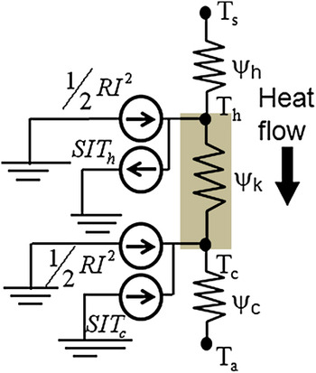
We developed a generic analytic one-dimensional model that includes a TE element (leg) with length d placed between a hot and a cold reservoir. The thermal resistance of the hot reservoir is given by  and that of the cold reservoir by
 , as shown in Fig. 1. Heat flux q h is supplied by the hot reservoir at temperature T s (fixed). Also, the cold reservoir T a (fixed) is given. The heat flux q c that flows into the cold reservoir is reduced from q h by an amount of useful power output w, depending on the energy conversion efficiency. This power output is extracted at the external electrical load resistor R L, which is electrically connected to the leg. By changing the leg length d, the temperatures at the hot and cold sides of the element are modified due to different heat flux and the Peltier cooling and heating at interfaces. To obtain the maximum power output, the co-optimization of the leg length and load resistance is carried out. In the later part of this section, we will introduce fill factor (heat concentration), spreading thermal resistance, and the number of elements in a module for more practical calculations.
A thermal resistance network showing a TE leg in contact with hot and cold reservoirs. Peltier and Joule heating sources are also shown.

We assume the unit cross-sectional area in this modeling. The following Eqs. (1) and (2) are derived based on the energy conservation at two temperature nodes, T h and T c, which are the temperatures at the hot side and the cold side of the TE leg.


Here, q is heat flux, β is the thermal conductivity, S is the Seebeck coefficient, I is the electrical current, and R is the internal electrical resistance. One should note that Joule heating happens everywhere in the TE leg. In one-dimensional heat transport, Joule heating could be represented by two localized sources at the hot and the cold junctions, each dissipating half of the total power. The useful power output is delivered to the load resistor. The power output per unit area of heat source w (W/m2) is found as

where  by energy conservation, σ is the electrical conductivity of the leg, d is the leg length, A is the area of the heat source, and m is the load resistance ratio of the external resistance to the internal resistance, i.e., R L = mR. Here, the area of heat source A and the cross-sectional area of a leg AE are the same.
We maximize the power output, which depends on the parameters m and d. To maximize, we also need to solve unknown parameters T h and T c. The Lagrange multiplier method was used for this optimization of multiple intrinsic parameters, see Ref. Reference Yazawa and Shakouri13 for details. Finding the Lagrange multiplier from Lagrange differentials of w with m allows us to find the optimum m, i.e., m opt, the multiplier in the Lagrange differentials of w in respect to d.
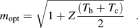
By knowing this optimum load resistance and through extensive numerical tests, we were able to obtain the optimum leg length d opt as

Here,  is the sum of the external thermal resistances, i.e.,
 . The m in the above Eq. (5) must simultaneously obey Eq. (4) to calculate the optimum leg length.
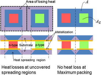
Now, the model needs a slight modification to consider the π-shape structure of n- and p-legs that forms the TE module with the substrates. Pairs of the p-type and n-type legs are connected in series for electrical connection and in parallel for thermal heat transfer point of view. Figure 2 shows a couple of elements in the module at maximum packing. The maximum element packing (right-hand side) is assumed so that all heat goes through the legs. In this analysis, we assume the same power factor and thermal conductivity for n-type and p-type elements. We define the fill factor F as the ratio of fractional area coverage of the element to the corresponding substrate area.

Geometrical configuration showing n- and p-legs electrically in series and thermally in parallel. Metallization and substrates are also shown. The right-hand side figure displays when the legs are at maximum packing.

where F is greater than 0 and less than or equal to 1. Heat concentration is given by 1/F. Thermal spreading and thermal contraction in the heat flow between substrates and a leg cause additional thermal resistances and increase the sum of the external resistances  in Eq. (5). See the supporting information of Ref. Reference Yazawa and Shakouri12 for the details of the thermal spreading model. Since the expression of the optimum leg length is linear to the sum of external thermal resistances, the spreading thermal resistances have an impact on power output. However, the weight power ratio (kg/kW) nearly converges to a constant dominated by the TE substrate at a smaller fill factor around a few percent.
By introducing fill factor F, the maximum module power output per unit area w max is

The mass per unit area of heat source G (kg/m2) of the TE module at the optimum design is

Here, ρTE is the density of the leg material, ρsub is the density of the substrate material, and d sub is the thickness of the substrates. The minimum cost per performance CP ($/W) of the TE power generator module becomes

where C TE and C sub are the unit mass price ($/kg) of the TE and the substrate material, respectively. Eqs. (8) and (9) are the direct functions of d opt. To simplify this dependency of the leg length for the weight and cost performance analysis, we introduce the element density N, which is a count of elements per unit area (1/cm2) for latter comparisons and total number of elements in the module is given by N × A × 104 as A is given in m2.
III. ANALYSIS AND DISCUSSION
A. Impact of fill factor on cost performance and weight performance
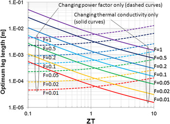
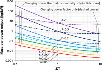
Based on the developed model, we calculated the optimum design of the thermoelement and the cost of the module by using the unit prices of materials. Assuming very large volume production, learning curves suggest that the minimum cost to build a TE power generator approaches the material cost, which directly follows the mass of the materials used. One should note that since we calculate the cost of the TE system per unit area, one can easily add the cost of manufacturing per unit area and study the impact of different fabrication techniques. Figure 3 shows the optimum leg length by changing the Z factor with variations of fill factor F. The solid curve shows the case of the changes in thermal conductivity. Similarly, the dashed curve shows the case of changes in power factor. We show the change relative to the current state-of-the-art material, which has a dimensionless figure-of-merit ZT of 1. These two curves show completely opposite trends. By improving only the power factor of the material, the optimum leg length becomes larger. Decreasing thermal conductivity leads to a shorter leg for optimum design. Hot and cold reservoir temperatures and heat fluxes are indicated in the caption of Fig. 3. One should note that while specific boundary conditions affect the actual output power and the energy cost ($/W), the general trends as a function of fill factor and ZT remain the same and the conclusions of the Fig. 3 remain valid. Eq. (7) shows the impact of changing the temperature difference, and Ref. Reference Yazawa and Shakouri12 summarizes how the energy cost is modified as a function of hot side heat flux and various heat sinks ranging from forced air to water cooling microchannels.
Optimum leg length versus ZT. The reference of the material property variation is set to β = 1.5 W/mK, and power factor = 3.35 × 10⁻³ W/mK2 (ZT ∼ 1). Heat transfer coefficients are U h = 4.62 × 10+2 W/m2K and U c = 1.54 × 10+3 W/m2K ( ), substrate thermal conductivity is 23 W/mK, and number of elements per unit area N = 100 (1/cm2).

In any material, electrical conductivity and electronic contribution to thermal conductivity are related by the Wiedemann–Franz (W–F) law, and Seebeck coefficient and electrical conductivity are related by the details of the band structure. In our calculations, we did not focus on any particular material system, and we study what happens if each of the material properties is independently changed. Our goal was to study the system impact of various parameters in ZT for different classes of materials. Once these trade-offs are identified, one can optimize a given material systems knowing the specific electronic band structure. We should also note that there is no “fundamental” limit that forbids a material with high electrical conductivity to also have high Seebeck coefficient (this can be achieved by using multiple bands, high effective mass, or by hot electron filtering). Also there is no “fundamental” limit on the low value of electronic thermal conductivity based on electrical conductivity of the material. There is always a Lorenz number relating electrical and thermal conductivities. This comes from fluctuation–dissipation theorem. However, the Lorenz number can be as small as possible as the width of the conduction band becomes narrower and narrower.Reference Humphrey and Linke14 This means that there is no upper band in ZT, and ZT in 0.1–10 range could be achieved in principle.
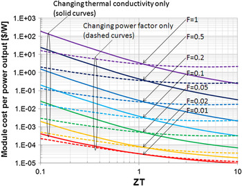
Considering the cost performance ($/W) in Fig. 4 or the weight performance (kg/kW) in Fig. 5, thermal conductivity reduction has a higher impact than the power factor enhancement. Thermal conductivity is a significant contributor at larger fill factors. However, the difference between changing thermal conductivity and power factor nearly diminishes at fill factors of 0.01 or smaller. The unit price of the TE material is fixed to 500 $/kg for 8.7 × 10+3 kg/m3 of mass density assuming similar costs to Bi2Te3. The unit price of the substrates is 5$/kg for 3.7 × 10+3 kg/m3 of mass density assuming the material is Alumina. Note that the minimum substrate thickness depends on the optimum leg length to satisfy the maximum packing constraint. The substrate thickness is optimized and varies between 17 μm and 0.6 mm for the above cases. Keeping in mind that the vertical axes of the Figs. 4 and 5 are in log scale, we can state that the reduction of fill factor yields a dramatic reduction of cost or weight per unit power output. For a convenient note, today’s material with ZT ∼ 1 could produce power of 1 W with 1 g of TE system using optimized design (fill factor of 0.05–0.07) for the exhaust gas energy recovery application.
Module cost performance ($/W) at the optimum leg length. The conditions are the same as in Fig. 3.

Weight per performance (kg/kW) of the TE module at the optimum leg length. The conditions are the same as in Fig. 3.

B. Impact of the number of elements
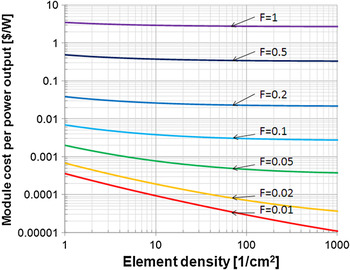
Smaller footprint of TE elements allows smaller gap spacing between them and does not require a thick substrate for thermal spreading. Thus, a higher density of elements per unit area can reduce the mass of TE module. Figure 6 shows the cost performance by changing the element density.
Element density—number of elements per unit area (1/cm2) for variations of the fill factor. ZT ∼ 1 and other conditions are the same as in Fig. 3.

C. Contact resistances
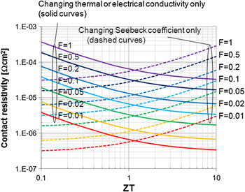
At the optimum leg length, we calculate the maximum contact resistances allowed for both the hot and cold sides of the elements. We set the parasitic Joule heating from these contact resistances to reduce the overall power generation by less than 5%, for example. In this particular case, with the material ZT ∼ 1, the maximum allowable contact resistivity for F = 1 is 6.6 × 10⁻⁵ Ω cm2; for F = 0.1, this is 6.7 × 10⁻⁶ Ω cm2; and for F = 0.01, this is 6.8 × 10⁻⁷ Ω cm2, while heat flux is 8 × 10+3 W/m2. These values could be considered an achievable target of a fabrication process. Figure 7 shows the impact of this contact resistivity at 5% power degradation. The requirement for the maximum allowable contact resistivity becomes tighter for higher ZT by reducing the thermal conductivity only because the thinner leg is required. However, the trend shows the opposite for the case of ZT enhancement by power factor. The power factor is the product of electrical conductivity and the square of the Seebeck coefficient by definition. Cost performance wise, the impact of the contact resistance is much smaller than the impact of the fill factor. Series resistance of the metal layer electrically connecting the legs is also considered. The transfer length for the current flow from TE leg into metal trace should be taken into account. As a result, a 7.6-μm thick copper trace is sufficient to maintain the sum of these resistances less than 5% of the electrical resistance of the leg, including the above range of the contact resistivity values.
Contact resistivity required at 5% power output degradation versus ZT for different fill factors. ZT ∼ 1 and other conditions are the same as in Fig. 3.

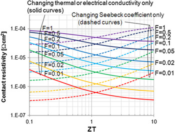
Next, we examine the impact of the contact thermal resistance at the boundary between TE leg and metallization. Although there is no comprehensive study relating electrical contact resistances and thermal contact resistances at metal/TE leg interfaces, we used the W–F law and calculated the resulting interface thermal resistance if Lorenz number of a typical metal is assumed. Figure 8 shows the allowable electrical resistivity at 5% power degradation including the additional thermal contact resistances at the hot side and the cold side. For F = 1, it is 5.2 × 10⁻⁵ Ω cm2; for F = 0.1, it is 6.2 × 10⁻⁶ Ω cm2; and for F = 0.01, it is 6.2 × 10⁻⁷ Ω cm2. The maximum allowable contact resistivity values at larger fill factors are slightly different compare to Fig. 7, which only considered the electrical contact resistance. The reoptimized leg length does not significantly change the power output even the sum of the additional thermal contact resistance is nearly 25% of the thermal resistance of the leg at ZT ∼ 1. With practical range or smaller range of fill factor, thermal contact resistances (based on W–F law assumption) can be neglected.
Contact resistivity required at 5% power output degradation versus ZT for different fill factors. Here, we used an additional interface thermal resistance between TE legs and metallization assuming W–F law is applicable for the contact interfaces. ZT ∼ 1 and other conditions are the same as in Fig. 3.

D. Additional heat losses
Pursuing smaller fill factors (higher heat concentrations) creates another parasitic effect. The heat leaking through the gap from the hot substrate to the cold substrate becomes significant for smaller fill factors. The total heat passing through the module is q as described in Eq. (10).

where βair is the effective pressure-dependent thermal conductivity of the air and ε is the emissivity of the interim surface of the substrates.
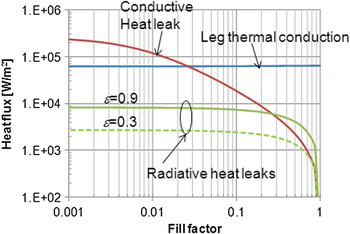
There are essentially two heat leak paths: conduction through the gap fill air and the thermal cross talk of the interim surface of the substrates by radiative heat transport. We neglect the internal convective heat transport since the gap is small enough to distract the air circulation by the gravity effect. In Fig. 9, the heat path through the element is nearly constant for different fill factors due to the thermal match to the external thermal resistances, while the conductive heat leak increases due to the smaller gap from a thinner leg length and a larger conductive area. The radiation heat transfer is only linear to the gap cross-sectional area with no relation to the leg length. Typical emissivity of ceramic substrates can be near 0.9.Reference He, Li, Wang, Sun and Zhang15 In this particular case, the radiative heat flux is an order of magnitude lower than that of the leg heat conduction (up to 8% of total heat transfer). If we use low emissivity shiny coating, e.g., 0.02 for gold coatingReference Aksyutov16, Reference Maki and Plyler17 at infrared wave lengths in this temperature range (up to 500 °C with the optimum leg thickness), the radiation component is negligible. Even a surface treatment with emissivity of 0.3 yields less than 3% of the heat flux of the leg thermal conduction when the exhaust gas temperature is ∼600 °C.
Heat leak path contribution as a function of fill factor. Same conditions as in Fig. 3 with β = 1.5 W/mK, power factor = 3.35 × 10⁻³ W/mK2 (approximately ZT = 1). The contribution of radiation is shown with emissivity of 0.9 (solid curve) and 0.3 (dashed curve).

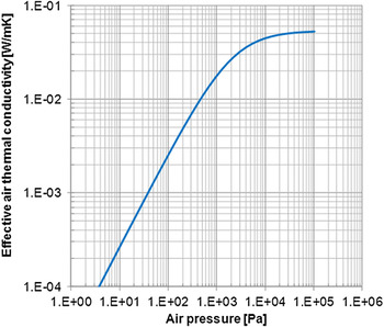
To reduce the dominant thermal conduction though the gap filling air at the smaller fill factor, we can lower the air pressure. The pressure dependency of the effective thermal conductivity of the air obeys Eq. (11), from Ref. Reference Potkay, Lambertus, Sacks and Wise18.
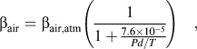
where βair,atm is the thermal conductivity of air at the atmosphere pressure, P (Torr) is the pressure, and T is the mean temperature. Figure 10 shows the effective thermal conductivity versus pressure. If the thermal conductivity of the TE material is 1.5 W/mK at a mean temperature of the application, the effective thermal conductivity of the empty regions should be less than 0.001 W/mK when fill factor F = 0.01, if we consider this parasitic heat path to be less than 5%–6% of the total heat flow. When F = 0.05, this requires an air pressure of 10 Torr and the effective thermal conductivity is 0.004 W/mK, and when combined with gold coating, ε = 0.02 for the interim surface of the substrates. Considering the additional costs associated with vacuum packaging, one may decide to use not too small a fractional coverage, for example, around F = 0.05.
Effective thermal conductivity of air by pressure.

The current analysis focused on the impact of material properties and module geometry. In an actual TE waste heat recovery system, one should include the power management and conditioning circuits. The hot side temperature varies as a function of driving conditions and vehicle loads. The full economic model should take into account the driving cycles and the cost of all the components of the system.
IV. CONCLUSIONS
We co-optimized the thermal and electrical parameters for TE power generation systems in contact with nonideal hot and cold reservoirs. A larger Z factor produces larger power output. However, the minimum cost per power or minimum mass per power differs if the improvement is by reducing the thermal conductivity or by increasing the power factor. Considering the fractional area coverage of the thermoelement, i.e., fill factor, in a π-shape structure module, the smaller fill factor provides an even more dramatic improvement to the weight per power ratio (kg/kW), which is directly connected to the generator cost ($/W). The lightweight power generators are very important for automotive applications. Too small fractional ratio of the elements, however, introduces parasitic heat losses by air thermal conduction and heat radiation. The contact material property and surface emissivity need to be considered since they can limit the system power output. A fill factor of around 0.05 (heat concentration of 20) seems to balance the trade-offs based on current material properties. With cheap vacuum packaging, lower fill factors can be more cost-effective. To highlight the general trade-offs between ZT improvement, material cost, and the impact of the fill factor, we assumed similar properties for n- and p-legs. If n- and p-type materials have different properties, one may adjust the cross section of each leg to maximize the power output. The impact of different n- and p-material properties will be discussed in a future work. We highlighted various trade-offs in the design of cost-effective TE power generation systems based on an example of the waste heat recovery from vehicle exhaust. The analytical model can be used to analyze the cost performance of other solid state TE energy conversion systems.
ACKNOWLEDGMENT
Authors would like to acknowledge the U.S. Department of Energy (DOE) Office of Science - Energy Frontier Research Centers (EFRC), Center of Energy Efficient Materials, and the Defense Advanced Research Projects Agency (DARPA) Defense Sciences Office (DSO) for financial support of this research.