I. INTRODUCTION
Since the US Federal Communications Commission (FCC) released the 3.1–10.6 GHz ultra-wideband (UWB) bandwidth [1], UWB communication systems have attracted great attention in the wireless world due to their advantages, including high-speed data rate and high capacity, while UWB antennas as the key components in the UWB communication systems have been deeply studied. Planar monopole antennas are found as good candidates for UWB applications [Reference Ammann and Chen2–Reference Ling, Lo, Yan and Chung5] owing to their fascinated features, such as ease of fabrication, simple structure, and good radiation properties. Many shapes of these antennas such as rectangular [Reference Ammann and Chen2], circular [Reference Liang, Chiau, Chen and Parini3], elliptical [Reference Agrawall, Kumar and Ray4], and binomial curved [Reference Ling, Lo, Yan and Chung5] types were proposed. However, many challenges still exist for UWB antennas design in practical applications. One such challenge is to eliminate the frequency interferences for UWB systems, since some wireless communication systems have already occupied operating frequency bands within 3.1–10.6 GHz of UWB band, such as WiMAX (3.3–3.8 GHz), IEEE 802.11 a (5.15–5.35 GHz & 5.725–5.825 GHz), and X-band satellite communication service (7.25–8.395 GHz). Therefore, it is significantly necessary to create UWB antennas with multiple notched bands.
Several methods to introduce notched bands were reported such as etching slots on the radiator [Reference Kim, Cho and Lee6], embedding spur lines on the feed line [Reference Zhao, Xu and Yin7], and adding a tuning metal stub to the antenna structure [Reference Pan, Duan, Tu and Jan8]. However, most structures in these antennas can only generate one notched frequency band, which means that multiple resonators are required to create multiple notched bands for an UWB antenna. This increases the complexity of UWB systems. Although many different multi-mode resonators have been adopted for multiple notched bands generation [Reference Sung9–Reference Xu, Zhang, Spiegel, Fan, Joines and Liu11], the frequency selectivity and bandwidths of the notched bands still need to be improved. Some band-notched UWB antennas with good frequency selectivity have been presented in [Reference Chuang, Lin and Chung12–Reference Tu, Li and Chu15]. However, the notched bands were generated by altering the structure of the radiation element, which may not easily apply or transfer to other UWB antennas with different radiation elements. Moreover, some of them [Reference Chu, Mao and Zhu14, Reference Tu, Li and Chu15] utilized two resonant elements (e.g. stub, slot, etc.) having two different resonant frequencies to create a wide notched band, which would result in the increase of the design complexity.
In this paper, a novel dual band-notched UWB monopole antenna using only one simple dual-mode resonator and two high-impedance lines has been proposed. With the help of two symmetrical outer high-impedance lines connecting with the microstrip feed line, the proposed dual-mode resonator can produce two stopbands with higher rejection level and better frequency selectivity than that of only one stopband using the same resonator without outer lines. To verify the proposed idea, a practical antenna example has been fabricated and measured.
II. RESONATOR ANALYSIS
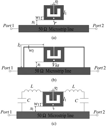
Figures 1(a) and 1(b) depict the layout of the conventional resonator and modified structure, respectively, which are used to generate notched bands for the UWB antenna. The conventional resonator is a folded half-wavelength resonator with a via hole in the center, while the modified structure is developed with two additional symmetrical high-impedance outer lines connecting the conventional resonator to the microstrip feed line.
Layout of: (a) the conventional resonator, (b) the proposed structure, and (c) the corresponding equivalent model.

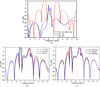
To investigate the frequency characteristics of the proposed structure, Fig. 2(a) demonstrates the frequency responses of three types of the resonators, which are all modeled on the substrate with a relative dielectric constant of 3.48, a thickness of 0.508 mm, and dielectric loss tangent of 0.004. The full-wave high-frequency structure simulator (HFSS) is employed to predict and study the performance of the proposed resonators. The resonator shown in Fig. 1(a) can obtain dual-resonance characteristics, while the one without via has only one resonant mode (see blue and black lines), which means the original resonant mode will be split to two modes by adding the inductive via [Reference Xu and Ai16]. Therefore, such two resonant modes can be combined together to form a wider notched band. The resonant frequency of this conventional resonator f r can be approximately calculated by
 $$f_{r} = \displaystyle{c \over {\lambda _{g} \sqrt {\varepsilon _{eff}}}} \approx \displaystyle{c \over {2l_1 \sqrt {(\varepsilon _r + 1)/2}}}, $$
where λ g denotes the guided wavelength, c is the velocity of light in free space, and ε eff denotes the effective dielectric constant of the substrate.
(a) Simulated results of three types of the resonators (l 1 = 15.24, l 2 = 14.6, w 1 = 0.7, w 2 = 0.1, S 1 = 0.2, S 2 = 0.16, and the radius of the via r = 0.2, all in mm); Simulated results of the proposed resonator equivalent model with (b) different L, where C = 0.075 pF, and (c) different C, where L = 10.5 nH.

To improve the suppression degree and frequency selectivity of the notched band, two symmetrical outer high-impedance lines are added connecting the conventional resonator to the microstrip feed line as shown in Fig. 1(b). With the help of these two high-impedance lines, the center frequency of the notched band is lowered and interestingly an extra stopband is generated. Compared with that of the conventional resonator, both of these two notched bands exhibit higher rejection level and better frequency selectivity with multiple zeros located at each side of the stopbands to improve the impedance matching performance. The high-impedance lines can be equivalent of series inductor–capacitor branch (see Fig. 1(c)), and the influence of inductor L and capacitor C on the resonator's frequency response is demonstrated in Figs 2(b) and 2(c) with the help of software advanced design system (ADS). It shows that the parameter C value of the proposed equivalent circuit model only affects the first stopband, while the other one remains almost constant. Both two stopbands show sensitive to the value of L.
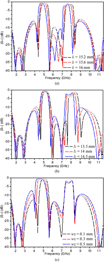
Figure 3 demonstrates the reflection coefficients against frequency with different dimensions of the proposed resonator. The center frequencies of two stopbands can be both lowered when l 1 increases, while other parameters are fixed (see Fig. 3(a)). Moreover, when the parameter l 2 rises, the center frequency of the upper stopband will decrease, but the lower stopband will be changed slightly as depicted in Fig. 3(b). In contrast, the center frequency of the lower stopband illustrates a significant decrease as w 2 increases, while the upper stopband remains unchanged (see Fig. 3(c)). The frequency responses of the parameters l 2 and w 2 agree well with the analysis results of the high-impedance lines equivalent circuit, since the values C and L are mainly determined by the width and length of the line, respectively, according to the transmission line theory. Therefore, the proposed equivalent model shown in Fig. 1(c) is reasonable, which can help to provide design guidance for the proposed resonator.
Simulated results of the proposed resonator with different (a) l 1, (b) l 2, and (c) w 2.

Based on the analysis above, two stopbands can be designed by carefully tuning the parameters of the proposed resonator. Taking the center frequencies of two stopbands at 5.2 and 7.8 GHz for instance, firstly, a resonator can be designed by tuning l 1 to make the lower stopband operate at 5.2 GHz. Then, change the parameter l 2 to make the upper stopband located at 7.8 GHz. In this step, the lower stopband will be changed slightly, but we can adjust the width of high-impedance lines w 2 to compensate this unwanted change because the upper stopband is fixed as shown in Fig. 3(c).
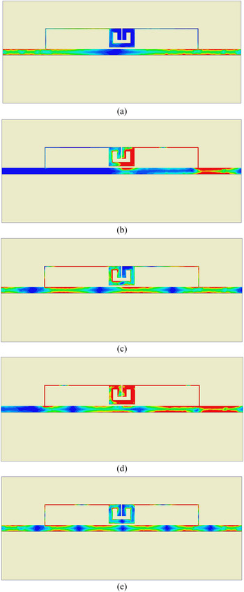
Figure 4 depicts the simulated current distribution on the surface of the resonator at five frequencies using HFSS, where the right- and left-side ports are the input and output ports of the bandstop filter, respectively. The areas marked in blue mean that the current is distributed weakly, while the current distribution is strong in the red areas. In Figs 4(b) and 4(d), the current is mainly concentrated on the input port and the proposed resonator for the frequencies within two notched bands, while the current distribution near the output port is weak. It is obvious that the signal power has been blocked by the proposed resonator. In contrast, the currents for the passband frequencies flow smoothly along the transmission line from input to output as shown in Figs 4(a), 4(c), and 4(e).
Simulated current distribution on the surface of the proposed resonator at (a) 2.8 GHz, (b) 5.1 GHz, (c) 7 GHz, (d) 7.5 GHz, and (e) 11.4 GHz.

III. DUAL BAND-NOTCHED UWB ANTENNA
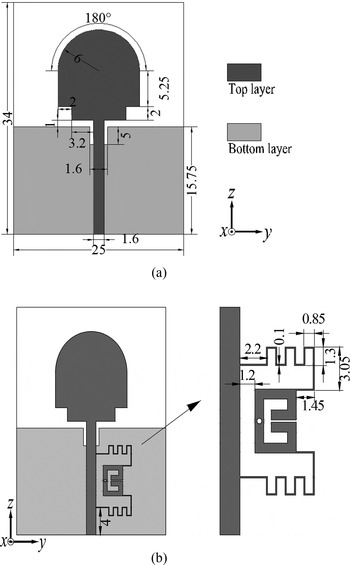
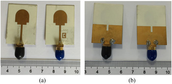
In order to validate the design idea of the proposed resonator, two UWB antennas with/without dual notched bands are designed on the RT/Duorid 4350 substrate with ε r = 3.48 and the thickness of 0.508 mm. The proposed UWB antenna without dual notched bands as the reference antenna consists of a microstrip feed line and a staircase-like tapered semi-circular patch on a truncated ground plane as shown in Fig. 5(a). A rectangle slot is etched on the bottom ground to improve impedance matching of the antenna. Figure 5(b) displays the proposed dual band-notched UWB monopole antenna with the above-mentioned bandstop filtering element beside the feed line. The outer high-impedance line is modified into a meandering shape to achieve size reduction. The dimensions of the proposed resonator were initially calculated by equation (1), and then HFSS was employed to optimize and determine the final dimensions of the whole structure based on the analysis as shown in Fig. 3. After simulated optimization, the dual band-notched UWB antenna and the reference antenna as its counterpart are both fabricated whose parameters can be seen in Fig. 5. The photographs of the fabricated dual band-notched UWB antenna and its reference antenna are displayed in Fig. 6. Compared with most previous published work where multiple resonators are required to create multiple notched bands for an UWB antenna [Reference Kim, Cho and Lee6–Reference Pan, Duan, Tu and Jan8], the proposed design greatly simplify the design process since only one multi-mode resonator is needed.
Layout of: (a) the reference UWB antenna and (b) the proposed dual band-notched UWB antenna (unit, mm).

Photograph of the fabricated dual band-notched UWB antenna as well as the reference antenna. (a) Top view and (b) bottom view.

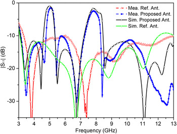
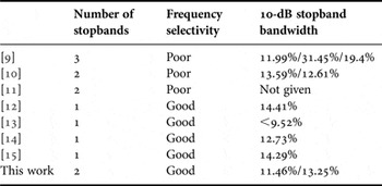
The simulated and measured reflection coefficients of the two UWB antennas are illustrated in Fig. 7, where they are all below −10 dB from 3.2 to 12 GHz except the dual notched bands. Two notched bands (S 11 > −10 dB) of 4.77–5.35 GHz and 7.26–8.29 GHz with sharp selectivity occur in the UWB frequency range. Table 1 exhibits the comparisons between the proposed antenna and the previous reported work [Reference Sung9–Reference Tu, Li and Chu15]. Although many papers such as [Reference Sung9–Reference Xu, Zhang, Spiegel, Fan, Joines and Liu11] using multi-mode resonators to generate more notched bands than one were reported, very few of them mentioned frequency selectivity and bandwidths of the notched bands. Compared with these [Reference Sung9–Reference Xu, Zhang, Spiegel, Fan, Joines and Liu11], the proposed structure has the advantage of high-frequency selectivity. Additionally, when it comes to the designs having high selectivity but with only one rejection band [Reference Chuang, Lin and Chung12–Reference Tu, Li and Chu15], our proposed design can achieve one more notched band. This feature shows a great advantage in the scenario where more than one unwanted wideband signal occurs and needs to be rejected. Moreover, note that the reflection coefficients of the proposed dual notched-band UWB antenna are significantly improved especially in the frequency range from 10.5 to 13 GHz compared with those of the reference antenna. This is because that the proposed bandstop filtering element can introduce multiple zeros to improve the impedance matching, which has been mentioned in Section II.
Simulated and measured results of the proposed antennas.

Performance comparisons between the proposed and other reported ones.

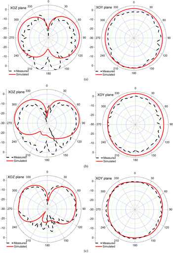
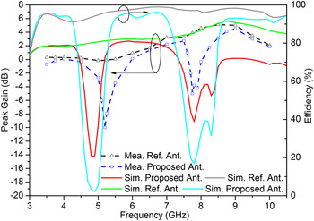
Figure 8 shows the simulated and measured radiation patterns of the proposed dual band-notched UWB antenna at 4, 6.5, and 10 GHz in the E-plane (XOZ-plane) and H-plane (XOY-plane). We can see that the antenna has good dumbbell-like radiation patterns in the E-plane and omnidirectional patterns in the H-plane. Moreover, the simulated and measured peak gains of the proposed and reference antennas as well as their efficiencies are plotted in Fig. 9. They significantly decrease at two notched bands due to the function of the proposed resonator structure. Compared with the simulated data including peak gains and efficiency, the measured center frequency of the low-frequency stopband increases while for the high-frequency stopband it slightly decreases. For the |S 11| in Fig. 7, it has the same observation about frequency offset between the simulated and measured results, where the measured center frequencies shift right for the low-frequency stopband and move left for the high-frequency stopband compared with the simulations of the |S 11|. The above-mentioned frequency offsets between the simulated and measured data may be attributed to unexpected tolerances in fabrication and material parameters, and another reason may be that the high-impedance line of the proposed resonators is located very close to the probe of the SMA connector as shown in Fig. 6, which leads to moderate deviation by the connector soldering.
Simulated and measured radiation patterns of the proposed antenna in the E- and H-planes at: (a) 4 GHz, (b) 6.5 GHz, and (c) 10 GHz.

Peak gains and efficiencies of the proposed/reference antennas.

IV. CONCLUSION
To obtain dual high-selectivity notched bands, a simple dual-mode resonator with two symmetrical outer high-impedance lines connecting to the microstrip feed line of the antenna has been proposed and applied in a planar UWB monopole antenna. Due to its simple structure and excellent performance, the proposed antennas are expected to be good candidates for use in UWB systems where unwanted wideband signals appear or rejected signals locate close to the desired signal.
ACKNOWLEDGEMENTS
This work was supported in part by the Natural Science Foundation of Fujian Province of China (Grant no. 2016J05164), Guangdong Natural Science Foundation (Grant no. 2016A030310375), and the Fundamental Research Funds for the Central Universities (Grant no. 20720160094).
 Yingjiang Guo was born in Sichuan, China. He received his B.E. degree in Electronic Engineering from Sichuan University (SCU), Chengdu, China in 2008, and received his M.E. degree in Electromagnetic Field and Microwave Technology from the University of Electronic Science and Technology of China (UESTC), Chengdu, China in 2011, where he is currently working toward the Ph.D. degree in Electromagnetic Field and Microwave Technology. From 2011 to 2013, he was with the Chengdu Research Institute of Huawei Technology Ltd., where he was involved in the pre-research of ultra-wideband power amplifier, high-frequency clock for AD, and 5G communication prototype building. From 2013 to 2014, he was with Sichuan Normal University, where he was a Lecturer. He has filed/granted a number of China patents in microwave circuit and internet of vehicle. His research interests include RF/microwave/mm-wave transceiver design and monolithic-microwave integrated circuit applications.
 Xiaohong Tang was born in Chongqing, China, in 1962. He received the M.S. and Ph.D. degrees in Electromagnetism and Microwave Technology from the University of Electronic Science and Technology of China (UESTC), Chengdu, China, in 1983 and 1990, respectively. In 1990, he joined the School of Electronic Engineering, UESTC, as an Associate Professor, and became a Professor in 1998. He has authored or coauthored over 80 technical papers. His current research interests are microwave and millimeter-wave circuits and systems, microwave-integrated circuits, and computational electromagnetism.
 Kai Da Xu received the B.S. and Ph.D. degrees in Electromagnetic Field and Microwave Technology from the University of Electronic Science and Technology of China (UESTC), Chengdu, China, in 2009 and 2015, respectively. He is now an Assistant Professor with Institute of Electromagnetics and Acoustics, and Department of Electronic Science, Xiamen University, Xiamen, China. From September 2012 to August 2014, he was a Visiting Researcher in the Department of Electrical and Computer Engineering, Duke University, Durham, NC, under the financial support from the China Scholarship Council (CSC). He received the UESTC Outstanding Graduate Awards in 2009 and 2015. He was the recipient of National Graduate Student Scholarship in 2012, 2013, and 2014 from Ministry of Education, China. He has authored and coauthored over 40 papers in peer-reviewed journals and conference proceedings. Since 2014, he has been served as a reviewer for some journals, including IEEE Transactions on Microwave Theory and Techniques, IEEE Transactions on Electron Devices, IEEE Transactions on Computer-Aided Design of Integrated Circuits and Systems, IEEE Transactions on Applied Superconductivity, International Journal of RF and Microwave Computer-Aided Engineering, ACES Journal, PIER, JEMWA, and Journal of Engineering. His research interests include RF/microwave and mm-wave circuits, antennas, and nanoscale memristors.
 Jing Ai received the B.S. degree in Electronic Science and Technology and M.S. degree in Electronic and Communication Engineering from the University of Electronic Science and Technology of China (UESTC), Chengdu, China, in 2007 and 2013, respectively, where he is currently working toward the Ph.D. degree in Electromagnetic Field and Microwave Technology. He worked as an Engineer in the Microwave Circuit and System Institute, Ya Guang Electronic, Inc. Aviation Industry Corporation of China (AVIC) from 2007 to 2013. His recent research interests include microwave and millimeter-wave circuits and systems.