1. Introduction
Recently, the repetitive positioning accuracy of most 6R industrial robots is higher than 0.1 mm, which can meet the basic requirements of electronic product manufacturing, automobile production, welding, and the other industrial applications. Nevertheless, with the development of technology, especially in the fields of aerospace and precision manufacturing, high absolute positioning accuracy of robots are requested to meet their production demands. The error factors impacting on the absolute positioning accuracy of robots primarily include kinematic parameter errors, dynamic errors, environmental impact, and load, etc. The errors of kinematic parameters account for 90% of the total error of the robot [Reference Wu, Klimchik, Caro, Furet and Pashkevich1]. Many researchers attempt to improve the absolute positioning accuracy of robots through a method of adjusting kinematic calibration of robot [Reference Sun, Lian, Yang and Song2–Reference Hayati and Mirmirani8], which only needs to modify kinematic parameters of the robots in Robot system control software. The kinematic parameter calibration is regard as a simple, effective, and economical method [Reference Sun, Lian, Yang and Song2], usually including four steps: modeling, measurement, identification, and compensation [Reference Wang, Gao, Kinugawa and Kosuge3–Reference Veitschegger and Wu6].
The Denavit–Hartenberg (DH) model is widely used in robot kinematic modeling; however, the original DH model may cause a singular problem when joint axes are parallel or approximately parallel to each other. To avoid this issue, Knasinski [Reference Judd and Knasinski7] and Hayati [Reference Hayati and Mirmirani8] introduced an additional rotational parameter about the Y-axis on the basis of the original DH model to build a new model named modified DH (MDH) model, which could solve the problem of the incompleteness of DH model. The kinematic error model established by MDH parameters is related to the structure of the robot, in which there are interrelated parameter errors, called redundant parameters. There are redundant parameters in the error model, which can affect the identification accuracy. Consequently, it is necessary to remove the redundant parameters [Reference Hage, Bidaud and Jardin9–Reference Joubair and Bonev13]. Fortunately, Meggiolaro [Reference Meggiolaro and Dubowsky14] proposed a method to remove the redundant parameters by analyzing the structural characteristics of adjacent joints of the robot, and this method promoted the accuracy of parameter identification. Gao [Reference Gao, Sun, Na, Guo and Wu15] used singular value decomposition (SVD) to remove these redundant parameters from the matrix. Furthermore, he proposed an innovative least square identification algorithm to estimate the structure parameters of the robot.
Kong [Reference Kong, Chen, Zhang and Wang16] employed the method of least square iteration in parameter identification and calculated the generalized inverse matrix using the method of matrix SVD. Also, he introduced the limit value of relative error tolerance to calculate the approximate values of parameters. In many studies, a high-resolution camera is installed at the end of the robot to ensure the measurement accuracy. For example, Wang [Reference Wang, Wu, Chen and Wang17] built a visual calibration method in terms of the point and distance constraints. This method was able to capture a fixed reference ball as a point constraint using a camera and could record the joint angle of the robot and the length of the measuring block as a distance constraint. In this research, the kinematic parameters were identified by Levenberg–Marquardt algorithm and the calibration accuracy increased from 2.05 mm to 0.24 mm. This method indicated the advantages of strong local convergence and good robustness, but at the same time it has the disadvantage of high requirements on hardware devices. Li [Reference Li, Zeng, Ehmann, Cao and Li18] transformed the overconstrained mechanism into a non-overconstrained mechanism in the robot, and he replaced the redundant constraint with generalized forces. He also established the kinematic model of the actual end position of the robot and the mechanical model of the non-overconstrained mechanism of deformation. Based on the robot’s overall kinematics model and the measured data, the structure parameters were identified by Newton–Raphson iteration and the least square method. The calibration results showed that the absolute positioning accuracy could be improved from 1.635 mm to 0.155 mm. Li’s model included kinematic model and mechanics model, which could achieve a higher accuracy. However, the established model is too complex for the practical applications. Joubair [Reference Joubair and Bonev19] proposed a kinematic calibration method based on distance and spherical constraints, which could fit multiple detection positions on the sphere to minimize the residual distance between the center of the sphere and the probe. Applied for the FANUC LR Mate 200iC robot, the average calibration error was reduced from 0.698 mm to 0.086 mm. Nevertheless, this method relied on external probe and required high machining precision. Nubiola [Reference Nubiola and Bonev20] adopted 29-parameter calibration error model, considering all possible geometric errors. Based on the IRB-1600 robot, 29-parameter errors were obtained by the least square method, and the average error was reduced from 0.968 mm to 0.364 mm. However, the entire measurement process needs to collect numerous points (1000) in the robot workspace, which takes a long time.
To enhance the absolute positioning accuracy of robots, more issues need to be solved. For instance, the control systems of most robots are not open to the public. Even if we can obtain all the parameter errors, we are not able to correct all of them. Additionally, the kinematic model has to satisfy the Pieper criterion; otherwise, it will be difficult to calculate the inverse kinematics. To find solutions for these two issues, this article proposed an innovative calibration method which transformes the 25-parameter errors model into 10-parameter errors model (namely T-10 parameter model). First of all, based on the MDH method, the 25-parameter error model is established, and the Automated Precision Inc (API)’s high-accuracy Radian laser tracker is used to measure actual sampling points. Secondly, redundant parameters in the error model were eliminated using the SVD. Thirdly, the error model without redundant parameters was transformed into a 10-parameter error model through Newton–Raphson method. Finally, 10-parameter errors were identified using the least squares methods, and the errors of identified parameters were compensated in the control software of the robot to verify that the proposed method can be applied to improve the absolute positioning accuracy of robot.
2. T-10 parameter calibration method
2.1. Robot error modeling
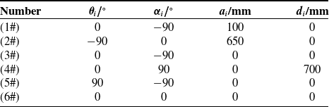
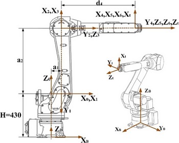
The Kawasaki RS010N industrial robot used in this study has an excellent environmental adaptability. The coordinate system of each joint of the Kawasaki RS010N robot is established based on the DH method, and its construct is shown in Fig. 1. The DH parameters of the robot are displayed in Table I. The joint rotation angle (
 $\theta$
) is obtained from the angle encoder installed in the servo motor of each joint of the robot. The link length (
 $a$
), the link offset distance (
 $d$
), and the joint twist angle (
 $\alpha$
) are generally fixed values, mainly determined by robot structure design, manufacturing, assembly, and the other factors.
DH parameters of the RS010N robot.

The structure and DH parametric coordinate system of the Kawasaki RS010N robot.

According to the principle of establishing homogeneous transformation matrix, the transformation from the coordinate system
 $\{o_{i-1}x_{i-1}y_{i-1}z_{i-1}\}$
to the coordinate system
 $\{o_{i}x_{i}y_{i}z_{i}\}$
includes a rotation and translation of a coordinate system. The four DH parameters of the robot linkage determine the spatial kinematics morphology of each link.
When robot joints are parallel to the axis or near than, singularity problem may occur, and the robot joints may be not able to satisfy the continuity of kinematics model. Therefore, increasing an additional rotation angle
 $\beta$
parameter on the Y-axis is to solve the adjacent joint axis parallel problem when caused by tiny errors and parameter changes, and the MDH model was established. Using the MDH modeling method, the transformation between linkage coordinate system
 $\{i-1\}$
and linkage coordinate system
 $\{i\}$
can be calculated through Eq. (1).
 $i=1\sim j$
.
 $j$
is the degree of freedom of robot joints. Then,
 $j{\gt}2$
 \begin{equation} \begin{array}{l} \displaystyle{\boldsymbol{T}}_{i-1}^{i}=\textit{Rot}\!\left(z_{i},\theta _{i}\right)\cdot \textit{Trans}\!\left(0,0,d_{i}\right)\cdot \textit{Trans}\!\left(a_{i},0,0\right)\cdot \textit{Rot}\!\left(x_{i},\alpha _{i}\right)\cdot \textit{Rot}\!\left(y_{i},\beta _{i}\right)\\[6pt] \displaystyle\left[\begin{array}{c@{\kern+5pt}c@{\kern+5pt}c@{\kern+10pt}c} \displaystyle c\theta _{i}c\beta _{i}-s\theta _{i}s\alpha _{i}s\beta _{i} & \displaystyle -s\theta _{i}c\alpha _{i} & \displaystyle c\theta _{i}s\beta _{i}+s\theta _{i}s\alpha _{i}c\beta _{i} & \displaystyle a_{i}c\theta _{i}\\[5pt] \displaystyle s\theta _{i}c\beta _{i}+c\theta _{i}s\alpha _{i}s\beta _{i} & c\theta _{i}c\alpha _{i} & s\theta _{i}c\beta _{i}-c\theta _{i}s\alpha _{i}c\beta _{i} & a_{i}s\theta _{i}\\[5pt] \displaystyle -c\alpha _{i}s\beta _{i} & s\alpha _{i} & c\alpha _{i}c\beta _{i} & d_{i}\\[5pt] \displaystyle 0 & 0 & 0 & 1 \end{array}\right] \end{array} \end{equation}
where
 $s$
and
 $c$
are short for
 $\sin$
and
 $\cos$
, respectively.
For the robots with multiple degrees of freedom, the errors in the coordinate system of each joint are transferred to the robot end, and the homogeneous transformation matrix of the joint to the robot end can be expressed as Eq. (2):
 \begin{equation} {}_{j}^{0}\boldsymbol{T}={}_{1}^{0}\boldsymbol{T}{}_{2}^{1}\boldsymbol{T}{}_{3}^{2}\boldsymbol{T}\cdots {}^{i-1}_{\,\,\,\,\,\,i}\boldsymbol{T}\cdots {}_{\,\,\,\,\,\,j}^{j-1}\boldsymbol{T}=\prod _{i=1}^{j}{}_{\,\,\,\,\,\,i}^{i-1}\boldsymbol{T} \end{equation}
The MDH parameters in Eq. (2) are all nominal values, and the homogeneous transformation matrix between the two coordinate systems is denoted as
 $\boldsymbol{T}_{i}$
. After introducing the MDH parameter errors of each joint
 $\Delta \theta _{i}, \Delta d_{i}, \Delta a_{i}, \Delta \alpha _{i}$
and
 $\Delta \beta _{i}$
, the resulting pose error
 $dT_{i}$
of the coordinate system can be shown in Eq. (3):
 \begin{equation} d\boldsymbol{T}_{i}=\boldsymbol{T}_{i}\cdot \Delta \boldsymbol{T}_{i}=\boldsymbol{T}_{i}\cdot \left[\begin{array}{c@{\kern+10pt}c@{\kern+10pt}c@{\kern+10pt}c@{\kern+10pt}c} \Delta \theta _{i} & \Delta d_{i} & \Delta a_{i} & \Delta \alpha _{i} & \Delta \beta _{i} \end{array}\right]^{T} \end{equation}
 $\Delta \boldsymbol{T}_{i}$
can be calculated as following:
 \begin{equation} \Delta \boldsymbol{T}_{i}=\left[\begin{array}{c@{\kern+8pt}c} \displaystyle \Delta \boldsymbol{R} & \Delta \boldsymbol{P}\\ \displaystyle 0 & 0 \end{array}\right] \end{equation}
where
 $\Delta \boldsymbol{R}$
is the rotation matrix of 3
 $\times$
3:
 \begin{equation} \Delta \boldsymbol{R}=\left[\begin{array}{c@{\kern+10pt}c@{\kern+10pt}c} \displaystyle 0 & -s\beta _{i}\Delta \alpha _{i}-c\alpha _{i}c\beta _{i}\Delta \theta _{i} & \Delta \beta _{i}+s\alpha _{i}\Delta \theta _{i}\\ \displaystyle s\beta _{i}\Delta \alpha _{i}+c\alpha _{i}c\beta _{i}\Delta \theta & 0 & -c\beta _{i}\Delta \alpha _{i}+c\alpha _{i}s\beta _{i}\Delta \theta _{i}\\ \displaystyle -\Delta \beta _{i}-s\alpha _{i}\Delta \theta _{i} & c\beta _{i}\Delta \alpha _{i}-c\alpha _{i}s\beta _{i}\Delta \theta _{i} & 0 \end{array}\right] \end{equation}
and
 $\Delta \boldsymbol{P}$
is the position matrix of 3
 $\times$
1:
 \begin{equation} \Delta \boldsymbol{P}=\left[\begin{array}{c} \displaystyle \mathrm{c}\beta _{\mathrm{i}}\Delta a_{i}-c\alpha _{i}s\beta _{i}\Delta d_{i}+a_{i}s\alpha _{i}s\beta _{i}\Delta \theta _{i}\\[6pt] \displaystyle s\alpha _{i}\Delta d_{i}+a_{i}c\alpha _{i}\Delta \theta _{i}\\[6pt] \displaystyle s\beta _{i}\Delta a_{i}+c\alpha _{i}c\beta _{i}\Delta d_{i}-a_{i}s\alpha _{i}c\beta _{i}\Delta \theta _{i} \end{array}\right] \end{equation}
According to the differential kinematics,
 $\Delta T_{i}$
can be also expressed as Eq. (7), and Eq. (7) includes the differential translation vector of 3×1
 $(dx_{i},dy_{i},dz_{i})$
and the differential rotation vector of 3×1
 $(\delta x_{i},\delta y_{i},\delta z_{i})$
:
 \begin{equation} \Delta \boldsymbol{T}_{i}=\left[\begin{array}{c@{\kern+10pt}c@{\kern+10pt}c@{\kern+10pt}c} \displaystyle 0 & -\delta z_{i} & \delta y_{i} & dx_{i}\\[6pt] \displaystyle \delta z_{i} & 0 & -\delta x_{i} & dy_{i}\\[6pt] \displaystyle -\delta y_{i} & \delta x_{i} & 0 & dz_{i}\\[6pt] \displaystyle 0 & 0 & 0 & 0 \end{array}\right] \end{equation}
Combining Eq. (5) and Eq. (7) to get Eq. (8), which demonstrates the position errors caused by the MDH parameter errors of any joint in the joint coordinate system
 $\{i\}$
, Eq. (8) is abbreviated as
 $e_{i}=G_{i}\Delta q_{i}$
:
 \begin{equation} \left[\begin{array}{c} \displaystyle dx_{i}\\ \displaystyle dy_{i}\\ \displaystyle dz_{i}\\ \displaystyle \delta x_{i}\\ \displaystyle \delta y_{i}\\ \displaystyle \delta z_{i} \end{array}\right]=\left[\begin{array}{l@{\kern+10pt}l@{\kern+10pt}l@{\kern+10pt}l@{\kern+10pt}l} \displaystyle a_{i}s\alpha _{i}s\beta _{i} & c\alpha _{i}s\beta _{i} & c\beta _{i} & 0 & 0\\ \displaystyle a_{i}c\alpha _{i} & s\alpha _{i} & 0 & 0 & 0\\ \displaystyle -a_{i}s\alpha _{i}c\beta _{i} & c\alpha _{i}c\beta _{i} & s\beta _{i} & 0 & 0\\ \displaystyle -c\alpha _{i}s\beta _{i} & 0 & 0 & c\beta _{i} & 0\\ \displaystyle s\alpha _{i} & 0 & 0 & 0 & 1\\ \displaystyle c\alpha _{i}c\beta _{i} & 0 & 0 & s\beta _{i} & 0 \end{array}\right]\left[\begin{array}{c} \Delta \theta _{i}\\ \displaystyle \Delta d_{i}\\ \displaystyle \Delta a_{i}\\ \displaystyle \Delta \alpha _{i}\\ \displaystyle \Delta \beta _{i} \end{array}\right] \end{equation}
The error in each joint coordinate system is transferred to the actual position coordinates of a robot’s tool center point (TCP), so the homogenous transformation matrix from the joint
 $i$
th to the TCP coordinate system is
 \begin{equation} {}^{n}{\boldsymbol{U}}{_{i}^{}}=\boldsymbol{T}_{i+1}\boldsymbol{T}_{i+2}\cdots \boldsymbol{T}_{t}=\left[\begin{array}{l@{\kern+6pt}l@{\kern+6pt}l@{\kern+6pt}l} \displaystyle n_{i} & o_{i} & a_{i} & p_{i}\\\displaystyle 0 & 0 & 0 & 1 \end{array}\right] \end{equation}
where n i =[n x n y n z ] T is the orientation of the X-axis of the end tool coordinate system with respect to the base coordinate system; where o i =[o x o y o z ] T is the orientation of Y-axis of the end tool coordinate system with respect to the base coordinate system; where a i =[a x a y a z ] T is the orientation of Z-axis of the end tool coordinate system with respect to the base coordinate system; where p i = [p x p y p z ] T is the position of the origin of the end tool coordinate system with respect to the base coordinate system.
Therefore, the total error model of the robot, which reflects the relationship between kinematics parameter errors of each joint of the robot and the end pose errors, is shown in Eq. (10):
 \begin{equation} \boldsymbol{e}_{n}=\sum _{i=1}^{n}{}^{n}{\boldsymbol{j}}{_{i}^{}}\boldsymbol{e}_{i}=\sum _{i=1}^{n}{}^{n}{\boldsymbol{j}}{_{i}^{}}\boldsymbol{G}_{i}\Delta \boldsymbol{q}_{i} \end{equation}
where
 ${}^{n}{\boldsymbol{j}}{_{i}^{}}$
is
 \begin{equation} {}^{n}{\boldsymbol{j}}{_{i}^{}}=\left[\begin{array}{l@{\kern+6pt}l@{\kern+6pt}l@{\kern+6pt}l@{\kern+6pt}l@{\kern+6pt}l} \displaystyle n_{ix} & n_{iy} & n_{iz} & \left(p_{i}\times n_{i}\right)_{x} & \left(p_{i}\times n_{i}\right)_{y} & \left(p_{i}\times n_{i}\right)_{z}\\ \displaystyle o_{ix} & o_{iy} & o_{iz} & \left(p_{i}\times o_{i}\right)_{x} & \left(p_{i}\times o_{i}\right)_{y} & \left(p_{i}\times o_{i}\right)_{z}\\ \displaystyle a_{ix} & a_{iy} & a_{iz} & \left(p_{i}\times a_{i}\right)_{x} & \left(p_{i}\times a_{i}\right)_{y} & \left(p_{i}\times a_{i}\right)_{z}\\ \displaystyle 0 & 0 & 0 & n_{ix} & n_{iy} & n_{iz}\\ \displaystyle 0 & 0 & 0 & o_{ix} & o_{iy} & o_{iz}\\ \displaystyle 0 & 0 & 0 & a_{ix} & a_{iy} & a_{iz} \end{array}\right] \end{equation}
2.2. T-10 parameter identification algorithm
According to Eq. (10), the error model of the multi-degree of freedom robot can be expressed as Eq.(12) [Reference Wu21]:
 \begin{equation} \boldsymbol{e}=\boldsymbol{M}_{\theta }^{i}\Delta \boldsymbol{\theta }_{i}+\boldsymbol{M}_{d}^{i}\Delta \boldsymbol{d}_{i}+\boldsymbol{M}_{a}^{i}\Delta \boldsymbol{a}_{i}+\boldsymbol{M}_{\alpha }^{i}\Delta \boldsymbol{\alpha }_{i}+\boldsymbol{M}_{\beta }^{i}\Delta \boldsymbol{\beta }_{i} \end{equation}
where
 \begin{equation} \left\{\begin{array}{l} \displaystyle \boldsymbol{M}_{\theta }^{i}=\left[\begin{array}{l@{\kern+6pt}l@{\kern+6pt}l} n_{i}k_{i}^{1}+\left(p_{i}\times n_{i}\right)k_{i}^{2} & o_{i}k_{i}^{1}+\left(p_{i}\times o_{i}\right)k_{i}^{2} & a_{i}k_{i}^{1}+\left(p_{i}\times a_{i}\right)k_{i}^{2} \end{array}\right]^{T}\\[5pt] \displaystyle \boldsymbol{M}_{d}^{i}=\displaystyle\left[\begin{array}{l@{\kern+6pt}l@{\kern+6pt}l} n_{i}k_{i}^{2} & o_{i}k_{i}^{2} & a_{i}k_{i}^{2} \end{array}\right]^{T}\\[5pt] \boldsymbol{M}_{a}^{i}=\left[\begin{array}{l@{\kern+6pt}l@{\kern+6pt}l} n_{i}k_{i}^{3} & o_{i}k_{i}^{3} & a_{i}k_{i}^{3} \end{array}\right]^{T}\\[5pt] \boldsymbol{M}_{\alpha }^{i}=\left[\begin{array}{l@{\kern+6pt}l@{\kern+6pt}l} \left(p_{i}\times n_{i}\right)\!k_{i}^{3} & \left(p_{i}\times o_{i}\right)\!k_{i}^{3} & \left(p_{i}\times a_{i}\right)\!k_{i}^{3} \end{array}\right]^{T}\\[5pt] \boldsymbol{M}_{\beta }^{i}=\left[\begin{array}{l@{\kern+6pt}l@{\kern+6pt}l} \left(p_{i}\times n_{i}\right)\!k_{i}^{4} & \left(p_{i}\times o_{i}\right)\!k_{i}^{4} & \left(p_{i}\times a_{i}\right)\!k_{i}^{4} \end{array}\right] \end{array}\right. \end{equation}
where
 $k_{i}^{1}=\left[\begin{array}{c} a_{i}s\alpha _{i}s\beta _{i}\\ a_{i}c\alpha _{i}\\ -a_{i}s\alpha_{i}{c}\beta _{i} \end{array}\right]$
,
 $k_{i}^{2}=\left[\begin{array}{c} -c\alpha _{i}s\beta _{i}\\ s\alpha _{i}\\ c\alpha_{i}{c}\beta _{i} \end{array}\right]$
,
 $k_{i}^{3}=\left[\begin{array}{c} c\beta _{i}\\ 0\\ s\beta _{i} \end{array}\right]$
,
 $k_{i}^{4}=\left[\begin{array}{c} 0\\ 1\\ 0 \end{array}\right]$
.
For 6R industrial robots, Eq. (12) includes the errors of 25 parameters (
 $\Delta \theta _{1}\sim \Delta \theta _{6}, \Delta d_{1}\sim \Delta d_{6}, \Delta a_{1}\sim \Delta a_{6}, \Delta \alpha _{1}\sim \Delta \alpha _{6}, \Delta \beta _{2}$
). However, in order to facilitate forward and inverse kinematics calculation during robot modeling, we set the parameters (α
1
∼ α
6, β
2, d
1 ∼ d
3, d
5, d
6, a
4 ∼ a
6) to fixed values. And the robot control system based on independent research and development only supports 10-parameter (
 $\theta _{1}\sim \theta _{6}, d_{4}, a_{1}\sim a_{3}$
) error compensation. Therefore, the errors of other kinematic parameters and their corresponding coefficient matrix columns in Eq. (14) are removed, and only 10 parameters are retained, and the influence of other parameter errors on the terminal is equivalent converted to these 10 parameters. By compensating the 10-parameter errors, the end position and pose errors are reduced. Therefore, Newton–Raphson algorithm is used to transform the 25-parameter errors into the 10-parameter errors that can be directly compensated, namely T-10 parameters model. The T-10 parameters model is given by Eq. (14):
 \begin{equation} \boldsymbol{e}=\boldsymbol{M}_{\theta }^{i}\Delta \boldsymbol{\theta }_{i}+\boldsymbol{M}_{d}^{4}\Delta \boldsymbol{d}_{4}+\boldsymbol{M}_{a}^{k}\Delta \boldsymbol{a}_{k} \end{equation}
where
 $k=1\sim 3$
.
Equation (14) is a non-square matrix model. Consequently, SVD is used to get the generalized inverse matrix of the extended Jacobi matrix ( J ), and J generalized inverse matrix can be expressed as Eq. (15):
 \begin{equation} \boldsymbol{J}^{+}=\boldsymbol{Q}\left(\begin{array}{cc} \boldsymbol{D}^{-1} & 0\\ 0 & 0 \end{array}\right)\boldsymbol{V}^{T} \end{equation}
where
 $\boldsymbol{V}$
and
 $\boldsymbol{Q}$
are both orthogonal matrices.
 $\boldsymbol{D}=\textit{diag}\!(\sigma _{1},\sigma _{2},\cdots,\sigma _{r})$
and
 $\sigma _{1}\geq \sigma _{2}\geq \cdots \geq \sigma _{r}\gt 0$
.
 $(\Delta \theta _{1}\sim \Delta \theta _{6},\Delta d_{4},\Delta a_{1}\sim \Delta a_{3})$
are the error values of T-10 parameter, which denote as
 $\Delta \boldsymbol{X}$
, and can be calculated by the least squares as shown in Eq. (16):
 \begin{equation} \Delta \boldsymbol{X}=\boldsymbol{J}^{+}\boldsymbol{e}=\boldsymbol{Q}\left(\begin{array}{cc} \displaystyle \boldsymbol{D}^{-1} & 0\\ \displaystyle 0 & 0 \end{array}\right)\boldsymbol{V}^{T}\boldsymbol{e} \end{equation}
3. Expermental verification
3.1. Experimental platform
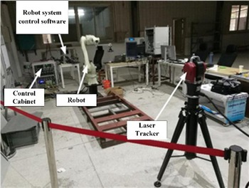
The calibration experimental platform was built (see Fig. 2) to verify the T-10 calibration method. The platform includes robot, Radian laser tracker, control cabinet, and Robot system control software.
Industrial robots’ calibration experimental platform.

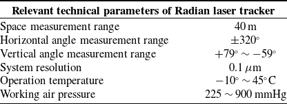
The Radian laser tracker [Reference Ye, Wang, Ren and Li22], produced by the automatic precision engineering company of the United States, was used to measure position points. Since the Radian laser tracker has a resolution of 0.1 μm in the effective working space and its measurement range can be up to 40 m, it is often used in a high-precision measurement. The primary performance indicators of Radian laser tracker are shown in Table II.
Primary performance indicators of Radian laser tracker.

3.2. T-10 calibration process
Since Eq. (12) contains 25 parameter errors, according to the least square theory, more than 25 equations need to be established, the more equations there are, the higher the accuracy of parameter identification will be. However, too many equations will increase the amount of calculation. After comprehensive consideration, 50 spatial positions were selected to establish the equation and 25 parameter errors were identified by the least square method.
Fifty position points in the workspace of robot were randomly selected, and the actual positions (
 $x_{c}$
,
 $y_{c}$
,
 $z_{c}$
) of robot terminal were measured by the laser tracker when the robot reached to these 50 position points. Then, the nominal positions (
 $x_{n}$
,
 $y_{n}$
,
 $z_{n}$
) were calculated through the Robot system control software. The deviations between the actual position values and the nominal position values could be computed for the 50 position points, respectively. The deviations values and joint rotation angle values (
 $\theta _{1}\sim \theta _{6}$
) of each point were substituted into the error model of Eq. (14) to identify the parameter errors.
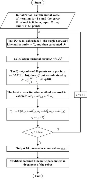
The calibration process (see Fig. 3) were described as follows:
The T-10 parameter identification process.

Step 1: The initial value of iteration was
 $i=1$
, and the error threshold was set at 0.1 mm. The Robot system control software controlled the robot to randomly move to 50 position points in the working space. At the same time, the Robot system control software recorded their
 $\theta _{1}\sim \theta _{6}$
and actual position values (P
c
) which were measured by the laser tracker.
Step 2: The
 $\theta _{1}\sim \theta _{6}$
of 50 points were substituted into the forward kinematics algorithm to calculate the nominal position values (P
n
i
) and the corresponding extended Jacobi matrix (J).
Step 3: The robot terminal errors (e i ) were calculated through e i = P c − P n i .
Step 4: The
 $\theta _{1}\sim \theta _{6}$
and e
i
of 50 position points were substituted in the error model Eq. (14). Subsequently, the extended Jacobi matrix (J
i
) was decomposed by the SVD algorithm Eq. (15) to eliminate redundant parameters. The generalized inverse matrix (J
i
+
) could be obtained by Eq. (16).
Step 5: The least square iteration method was used to estimate the linear equation
 $(\Delta X_{i}=\Delta X_{i-1}+J_{i}^{+}\cdot e_{i})$
, that is, the T-10 parameter error values
 $(\Delta X_{i})$
were obtained, where “i” was the number of iterations.
Step 6: The transformed 10-parameter error values
 $(\Delta X_{i})$
plus the nominal MDH parameters into the forward kinematic equation. Then, returned to Step 2 and Step 3 to recalculate P
n
i + 1
and recalculate terminal errors (e
i + 1
).
Step 7: If e i + 1 was less than or equal to 0.1 mm, the transformed 10-parameter errors were outputs (see Step 8); otherwise, the program would return to Step 4 and continue to execute the program.
Step 8: The T-10 parameter errors were compensated into the Robot system control software, to complete the kinematic calibration.
3.3. Direct-10 (D-10) calibration
Since the robot kinematics model needs to meet the Pieper criterion, it is not able to compensate all the identified parameters and it can only support the compensation of 10 parameters (
 $\Delta \theta _{1\sim 6}$
,
 $\Delta d_{4}$
,
 $\Delta a_{1\sim 3}$
). Thus, the 10-parameter errors in identificated 25 parameters are used to modify the Robot system control software for conducting compensation and calibration. This method is defined as direct compensation for 10 parameters, abbreviated as D-10 parameters.
Kinematic parameter identification of robot was a nonlinear iterative process. In order to obtain higher identification accuracy, 50 position points were randomly selected in the robot workspace. The kinematic parameter errors were identified, and the corresponding 10 parameters were modified using the Robot system control software to achieve compensation. After compensation, the Robot system controlled the robot to move to another more 25 position points randomly in the workspace to confirm the effect of compensation.
4. Results and discussion
4.1. Calibration test of ER6B-C60 robot
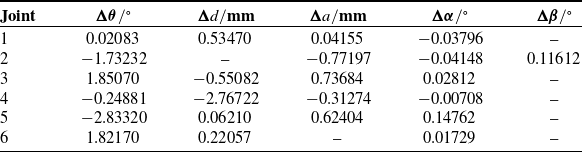
The MDH parameter errors of each joint were obtained (see Table IV) by calculating the 25-parameter errors identification. In Table IV, we got 23 parameter errors after removing redundant parameters of
 $\Delta d_{2}$
and
 $\Delta a_{6}$
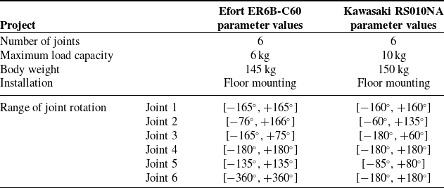
. The D-10 parameters were directly compensated through the Robot system control software. The parameters of ER6B-C60 are shown in Table III.
The main technical parameters of the two robots.

Identification results of 25-parameter errors.

Note: ‘–’ represents an unrecognized parameter.
According to the proposed T-10 parameter calibration method, 10-parameter errors which could be compensated directly were calculated through transformation, and the results were shown in Table V.
Identification results of T-10 parameters method.

By comparing Table IV to Table V, it indicates that the variation range of
 $\Delta \theta _{1\sim 6}$
in the 10 kinematic parameter errors directly compensated is not large, but the kinematic parameter errors of link offset distance vary dramatically and the maximum difference (
 $\Delta d_{4}$
) is around 1 mm. The T-10 parameter calibration method mainly converts the remaining 13 parameter errors into the parameter errors of the link offset distance.
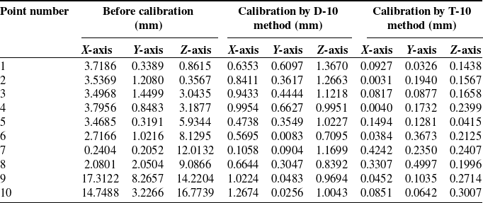
After compensating 10-parameter errors of D-10 method and T-10 method, respectively, another 25 position points in the robot workspace were selected and measured by the laser tracker. Table VI contains the position errors of any 10 position points in the robot workspace along the X-, Y-, and Z-axes of the robot. It can be seen that the position errors of the robot in three directions are greatly reduced after compensation. For example, before calibration, the maximum error of the robot’s Z-axis is over 16 mm; however, after D-10 calibration, the Z-axis errors were solely about 1 mm. Using the T-10 calibration method proposed in this paper, the Z-axis errors could be below 0.4 mm and the position accuracy was effectively improved.
Position errors of the robot along the X-, Y-, and Z-axes randomly 10 measurement position points.

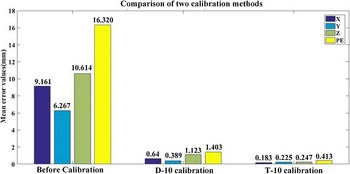
To further analyze and compare the position errors (PE) of the 25 position points, Fig. 4 displays the MAE (mean absolute error) of the 25 position points under before calibration, using D-10 calibration method and using T-10 calibration method. MAE reflects the average accuracy of the robot. Before calibration, the mean Z direction position error is the largest in the mean direction position errors, which is 10.614 mm. After D-10 calibration, the mean position error in Z-axis error is reduced to 1.123 mm, and the accuracy is improved to some extent. Finally, the proposed T-10 calibration method is applied to the calibration of kinematics parameters of the ER6B-C60 robot, and the mean Z-axis error is further reduced to 0.247 mm. The average PE
 $(PE=\sqrt{X^{2}+Y^{2}+Z^{2}})$
is reduced from 16.320 mm before compensation to 0.413 mm by T-10 calibration method, and the positioning accuracy was improved by 97.47%. The experimental results showed that the T-10 calibration method can effectively improve the absolute positioning accuracy of the robot and reduce the fluctuation of position errors.
MAE (mean absolute error) of the 25 poisition points within the workspace.

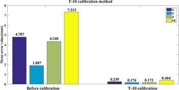
In order to confirm the compensation effect of T-10 calibration method, another robot of the same model robot (ER6B-C60) was selected for testing. The calibration result is shown in Fig. 5. The absolute positioning accuracy reached 0.404 mm, and the calibration results indicated that the T-10 calibration method had the same compensation effect to the same model robot.
4.2. Calibration test of Kawasaki RS010NA robot
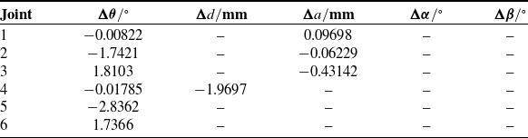
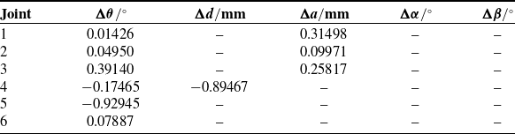
In order to verify the universality of T-10 calibration method, using the T-10 method proposed in this study, calibration tests were conducted on different model (Kawasaki RS010NA) industrial robot. The parameters of RS010NA robot are shown in Table III. The T-10 parameter errors were calculated, and the results were demonstrated in Table VII.
Identification results of Kawasaki RS010NA robot.

MAE of the 25 poisition points within the workspace.

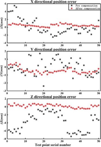
After T-10 calibration, the 50 position errors of Kawasaki RS010N robot were statistically analyzed from X, Y, and Z directions and compared with the values of before calibration, errors as shown in Fig. 6.
The calibration of before and after 50 points in X, Y, and Z direction errors.

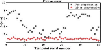
After calibration, the position errors curves in the X, Y, and Z directions all approaches to the zero line, and their mean error is about 0.5 mm. The accuracy in the Z-axis is more obviously promoted than that in the X-axis and Y-axis. The PE after calibration is shown in Fig. 7.
In Fig. 7, comparing with position errors before calibration, the error after calibration mainly fluctuated within the range of
 $\pm 1.2\,\text{mm}$
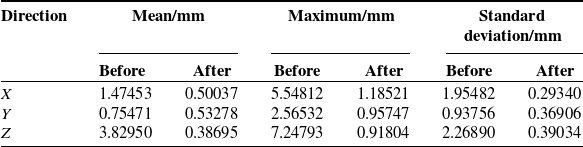
. For more intuitive display, 50 position points were statistically analyzed and statistical. The result from Table VIII indicated that the Z-axis error before calibration was the largest. After calibration, the maximum Z-axis error was decreased from 7.24793 mm to 0.91804 mm (reduced 89.92%). In addition, the standard deviation of Z-axis decreased from 2.26890 mm before calibration to 0.39034 mm.
Results statistics of 50 test points.

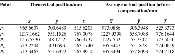
Average position value before fixed point compensation.

The calibration of before and after 50 points position errors.

4.3. Position accuracy test
In the previous section, error compensation verification was conducted on 50 randomly sampled points, and the results showed a significant improvement in the end-point positioning accuracy of the robot after compensation. To further validate the effectiveness of this calibration method in improving the accuracy of the robot in other positions in its workspace, the end-point positioning accuracy of the Kawasaki RS010NA industrial robot was tested according to the specifications of “GB/T12642-2013 Performance Specification and Test Methods for Industrial Robots” [Reference Shuping, Li and Haidan23]. This experiment consisted of three groups: pre-compensation position accuracy testing, direct 10-parameter compensation position accuracy testing, and transformed 10-parameter compensation position accuracy testing.
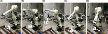
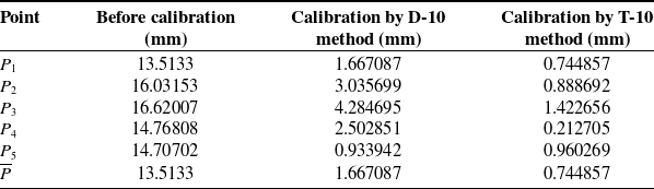
The testing method is as follows: a square area is selected in the front of the robot’s workspace. The theoretical position information of five test points is calculated and inputted into the robot’s upper computer program in the format of teaching text. The theoretical point position data is shown in Table IX. The robot is then controlled to move in a sequential order corresponding to the test points (Fig. 8 shows the actual positions of the robot at the five test points). The robot stays at each position for 10 s, and the actual positions of the five points are measured using a laser tracker. A total of 30 cycles are executed, resulting in 30 sets of data with 5 points each, for a total of 150 measured position data points.
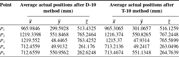
The first group of experiments is the precision testing of the test points before compensation. Following the aforementioned steps, the positions of the test points before compensation are measured, and the recorded data is shown in Table IX.
In the second group of experiments, the parameter errors identified are compensated using the D-10 method. The instruction poses for these five validation points are re-issued to the robot. The robot is then operated in the same manner, repeating the cycle of motion 30 times. The actual positions reached by the five validation points after compensation are measured using a laser tracker. The average position for each measured point is shown in Table X.
Average position value after fixed point compensation.

In the third group of experiments, the parameter errors identified are compensated using the T-10 method. The instruction poses for these five validation points are re-issued to the robot. The robot is then operated in the same manner, repeating the cycle of motion 30 times. The actual positions reached by the five validation points after compensation are measured using a laser tracker. The average position for each measured point is shown in Table X.
Actual location of five test points.

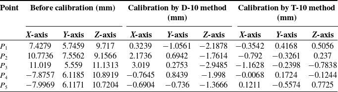
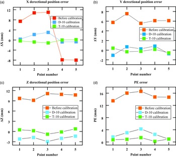
To better illustrate the advantages of the T-10 method, the position data before compensation, the position data after compensation using the D-10 method, and the position data after compensation using theT-10 method are processed. The deviations between these data and the theoretical position data in the X, Y, and Z-axis directions are calculated. The results are shown in Table XI and Fig. 9(a–c).
Position errors of the robot along the X, Y, and Z axes.

Actual location of five test points.

To better illustrate the advantages of the D-10 method, the PE errors for the five position points are calculated for each method. The average of the absolute values of the PE errors is also calculated. The results are shown in Table XII and Fig. 9(d).
The difference between the actual position PE value and the theoretical PE value for each method.

It can be seen from Table XI that before compensation, the error of the robot’s fixing point in the X-axis direction can reach up to 11.019 mm, the error of Y-axis can reach up to 7.5562 mm, and the error of Z-axis can reach up to 11.1313 mm. After compensation by D-10 method, the X-axis direction error is reduced to 3.019 mm, Y-axis error is reduced to 1.0561 mm, and Z-axis error is reduced to −2.9485 mm. After compensation by T-10 method, the deviation of the X-axis is reduced to 1.1628 mm, the Y-axis error is reduced to 0.5574 mm, and the Z-axis error is reduced to 0.7838 mm. Table XII shows that after D-10 method compensation of the robot, the average value of the absolute PE error at five points decreased from 15.1280 mm to 1.1546 mm, and after T-10 method compensation, the average value of the absolute PE error at five points decreased to 0.4256 mm. Through these data, it can be seen that the error of the robot is obviously reduced and the position accuracy of the robot is greatly improved after the compensation by T-10 method.
4.4. Tool center point (TCP) test
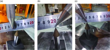
TCP testing was conducted to further verify the effect of the calibration. Usually, the test of the TCP rotating around thimble performs the robot’s dynamic precision, and it reflects the dynamic effect after calibration. TCP testing is divided into three steps: (1) using the six-point method to calibrate TCP; (2) carrying out the centering test of TCP; and (3) measuring the result of TCP winding test.
Before TCP testing, the values of the MDH parameter errors were calculated and compensated into the Robot system control software. Furthermore, the TCP coordinate system was re-calibrated. The TCP of robot was controlled to rotate around thimble with a certain angle. The robot calibration effect was verified by measuring the error of TCP after rotation.
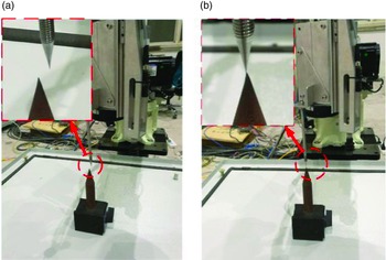
Without calibration, the ER6B-C60 robot TCP rotates along the Z direction of the base coordinate system, and the maximum TCP error is 15 mm (see Fig. 10a). After D-10 calibration, the maximum TCP error is about 2 mm (see Fig. 10b), while after T-10 calibration, the maximum TCP error is about 1 mm (see Fig. 10c). It indicates that T-10 calibration is more effective to improve the dynamic accuracy of the robot. The TCP accuracy of Kawasaki RS007L robot has been improved from 5 mm to 1 mm (see Fig. 11).
TCP test of Kawasaki ER6B-C60 robot. (a) Before compensation. (b) D-10 calibration. (c) T-10 calibration.

TCP test of Kawasaki RS007L robot. (a) Before calibration. (b) T-10 calibration.

All the above experimental results show that compared with the D-10 calibration method, the T-10 calibration method could further improve the absolute positioning accuracy of the robot. As mentioned earlier, the D-10 calibration method adopted the direct compensation of 10 parameter errors, which is difficult to compensate the errors of the other kinematic parameters. However, the T-10 calibration method converted all identified kinematic parameter errors into 10 parameter errors which can be directly compensated by the Newton–Raphson method; therefore, it can indirectly realize full kinematic parameter error compensation and further improve the absolute positioning accuracy of the robot. In the 29-parameter calibration model adopted by Nubiola, he also used the laser tracker to obtain the actual error value of the robot; however, 1000 position points were measured in the entire measurement process, and the calibration efficiency was low. In terms of compensation accuracy, the T-10 calibration method proposed in this research only needs 50 points selected in the robot workspace, and obviously the calibration efficiency was improved significantly. By converting to 10 parameters for compensation, the actual compensation effect was similar as or even better than the effect proposed by the Nubiola’s method.
5. Conclusion
To improve the absolute positioning accuracy of industrial robots without modifying kinematic structure and requiring the opening of controller, an innovative calibration method to compensate all parameter errors of 6-DOF industrial robots is proposed. The procedures of the calibration method are threefold. Firstly, the robotic 25-parameter error model is established, in which all possible 25 parameter errors of kinematics were considered. However, the robot structure may result in redundant parameters in the error model, and therefore, SVD algorithm is adopted to remove these redundant parameters. Subsequently, the error model without redundant parameters is transformed into a 10-parameter error model through Newton–Raphson method. Finally, 10-parameter errors are identified using the least squares methods, and the errors are directly compensated to the corresponding nominal MDH parameters. In order to explore the compensation’s effect, some robot workspace position points (e.g., 50 or 25 points) are randomly selected and the absolute positioning accuracy is measured by Radian laser tracker. And the TCP test (rotating around thimble) is conducted to estimate the error. The entire experimental results indicate that the T-10 method can greatly improve the absolute positioning accuracy of the robots.
The method proposed in this research has the following advantages. First, in the method, the opening of the control system is not required, and parameters can be easily modified in the software of the upper control. Second, without modifying the forward and inverse kinematics, all the kinematic parameter errors can be indirectly compensated, and the positioning accuracy of the robot can be effectively improved. Finally, the measurement process is relatively simple.
Admittedly, the calibration methods should be improved in two aspects. For instance, in this study, only the impact of kinematic parameter error is considered. To further improve the absolute positioning accuracy, the non-kinematic parameters should be also applied to the model. Additionally, the influence of measurement noise may impact the accuracy of parameter identification; therefore, measurement noise should be considered in the future research.
Acknowledgments
Not applicable.
Author contributions statement
Pinguang Nie and Chengqi Meng were the experimental designers and executors of the study. They completed the data analysis and wrote the first draft of the paper. Xuhong Chen and Bingqi Jia participated in the experimental design and analysis of experimental results. Lin Chen and Haihong Pan were the framers and principals of the project, guiding the experimental design, data analysis, paper writing and revision. All the authors read and agreed to the final text.
Funding statement
The author thanks the National Natural Science Foundation of China (No.51465005), Guangxi Innovation-Driven Development Special Project (No.AA18118002), 2017 Nanning High-level Entrepreneurial and Innovative Talents Funding Project for financial support.
Ethical statement
The authors declared that they have no conflicts of interest to this work. We declare that we do not have any commercial or associative interest that represents a conflict of interest in connection with the work submitted.