




No CrossRef data available.
Feature modeling using a grammar representation approach
Published online by Cambridge University Press: 02 November 2005
Abstract
In intelligent computer-aided design the concept of intelligence is related to that of integration. Using feature-based computer-aided design models is thought to make a complete integration. This paper presents a feature recognition approach based on the use of a feature grammar. Given the complexity of feature recognition in interactions, the basic idea of the approach is to find the latent and logical structure of features in interaction. The approach includes five main phases. The first phase, called regioning, identifies the potential zones for the birth of features. The second phase, called virtual extension, builds links and virtual faces. The third phase, called structuring, transforms the region into a structure compatible with the structure of the features represented by the feature grammar. The fourth phase, called Identification, identifies the features in these zones. The fifth phase, called modeling, represents the model by features. The feature modeling system software is developed based on this approach.
Information
- Type
- Research Article
- Information
- Copyright
- © 2005 Cambridge University Press
1. INTRODUCTION
Today, computer-aided design (CAD) is used at all levels in the design process, from conceptualization to documentation. The introduction of solid modelers made it possible to unambiguously define the geometric models of parts. This type of modeler provides a complete representation of the shape of the part, offering sufficient information about its geometry and topology. Thus, this type of representation is increasingly popular in various applications used in the product development process.
Despite these advantages, these modelers only take into account the product shape, but do not include the various types of knowledge required to build and utilize it. The introduction of the concept of features made it possible to associate shape and knowledge in understanding a CAD model.
Features are generic or specific shapes with which engineers associate certain attributes and business knowledge used in various development phases. To use features as a means for integration, we must find ways to transform their representation when moving between applications. This problem involves, on the one hand, transforming a geometric model for the part into a feature-based model adapted to the desired view, and on the other hand, enabling the transformation of features between views (Bronsvoort & Jansen, 1993; Laako & Mäntylä, 1993; De Martino & Gianini, 1994). The transformation, which is developed based on a geometric model to other models representing different application views, is called automatic feature recognition.
Automatic feature recognition is a process for transforming one representation into another. More specifically, we can say that the process defines the transformation of all the lower level CAD model entities such as primitives, faces, edges, and nodes into features. Automatic feature recognition must resolve the following problems: feature representation and feature recognition. The first problem involves choosing or developing a approach suitable for representing features so that their representation is unique. The second problem involves developing inference procedures able to perform the most complete recognition possible. Directed to these problems, two classes of feature recognition approaches can be distinguished: decision–theoretical approaches and structure–handling approaches.
In the decision–theoretical approaches, a feature is represented as a vector, giving information about one face of the feature and its relationships to other faces. A face definition consists of face geometry and a set of bounding edges and vertices. If a value is assigned to the edges and vertices based on their geometric and topological information, then a face score will summarize the important properties of the face. If the face scores are evaluated for all faces in the object, then the collection of face scores describes the local behavior and can form a face score vector. Thus, features can be defined as the region comprising the faces of the object, characterized by a specific face score gradient. The definition of a feature depends on identification of the primary face of a feature, which is defined as the face with the highest score in the defined region (Henderson, 1994). The disadvantage of this approach is its lack of suitable formalism for handling feature structures and their relationships.
In the structure–handling approaches, features are represented based on their logical structures and their relationships. Structure–handling approaches deal with the explicit knowledge, a capability lacked by decision–theoretical approaches. The basic idea of these approaches is to search the logical latent structure of features. Here, the main automatic feature recognition approaches are based on graph theory (Ansaldi et al., 1985; Joshi & Chang, 1988; Marefat & Kashyap, 1990), expert systems (Henderson & Anderson, 1984; Bond & Chang, 1988; Choi et al., 1988); volume-based decomposition (Woo, 1982; Kim, 1992; Kim & Wilde, 1992; Menon & Kim, 1994), and the syntactic approach (Srinavasan et al., 1985; Li, 1988; Falcidieno & Gianini, 1989).
Graph theory is a popular method used to represent the topological relationship of features. For instance, the attributed adjacency graph is used for feature representation (Joshi & Chang, 1988). An attributed adjacency graph is defined as G(N, A, T), where N is the set of nodes, A is the set of arcs, and T is the set of attributes assigned to arcs in A. Each face of features is represented as a node, and each edge or face adjacency is shown as an arc. The attribute is assigned “1” if the two adjacent faces form a convex angle and “0” if the angle is concave. For each feature type a rule, usually the first-order one, based on the graph theory is developed.
The expert system approach represents the features by some rules of logic (Henderson & Anderson, 1984; Bond & Chang, 1988; Choi et al., 1988). They are the production rules in the logic of the first order using geometrical and topological relationships (Henderson & Anderson, 1984).
The volume decomposition approach is based on the assumption that a feature can be represented as a volume or a sum of smaller volumes. A convex decomposition called alternating sum of volumes with partitioning is developed (Woo, 1982; Kim, 1992; Kim & Wilde, 1992; Menon & Kim, 1994). There are two stages in that approach: the decomposition, and converting of the decomposition into form features.
The syntactic approach is based on the decomposition of features into subpatterns or primitives. By tracking the features patterns in one direction, it is possible to detect and encode these primitives in the form of string of qualifiers. Suppose that one can interpret each primitive as being a symbol permissible in some grammar, where a grammar is a set of rules of syntax for the generation of sentences from the given symbols; then, a language is generated by this grammar. The sentences of this language represent the features (Srinavasan et al., 1985; Li, 1988; Falcidieno & Gianini, 1989).
Automatic feature recognition is a complex process. Despite major developments in this area, several problems remain. Thus, feature recognition in interaction remains an area for research. In the case of design, a finite set of canonical features can produce an unlimited number of configurations of features in physical interaction. The physical interaction between canonical features can deform their initial representation. Indeed, the representation of a feature, resulting from the physical interaction between canonical features, is dissimilar from the representation of canonical features. Furthermore, the representation of a canonical feature as a component of a resulting feature may be different from its initial representation. Listing all the features in interaction appears to be a utopian task of very little interest (Marefat & Kashyap, 1990).
This paper discusses the problem of recognizing canonical features and features in interactions. In the second section, using the hypothesis that a product has a final structure that is the result of an ideal evolution from a set of significant structures, we propose a feature grammar for their representation. Consideration of the semantic and uncertain aspects generalized the feature grammar by producing the conditional and fuzzy features grammar. The third section presents a recognition approach based on the conditional and fuzzy features grammar. Examples and the application illustrate the steps involved and the advantages of this approach.
2. FEATURE REPRESENTATION
2.1. Topological and geometric entity graph
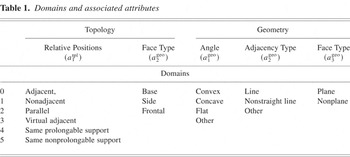
A feature is a geometric entity defined by its shape and technological characteristics, typically represented by a set of topologically associated faces. Given two finite, nonempty sets Dtpl = {D1tpl,D2tpl · · · Dmtpl} and Dgeo = {D1geo, D2geo · · · Dngeo}, which are called the set of topological domains and the set of geometric domains, respectively; two sets of attributes Atpl = {a1tpl, a2tpl · · · amtpl} and Ageo = {a1geo, a2geo · · · angeo}, which are called the set of topological attributes and the set of geometric attributes, respectively, where each attribute is associated with each domain; and X = {X1, X2 · · · Xi · · · Xm}, which is a set of features. Then, any shape feature Xi can be characterized by a set of faces F = {f1, f2 · · · fi · · · fm} that satisfy a set of topological and geometric relations. These relations are defined for domains corresponding to the set of topological and geometric attributes, respectively. Table 1 shows typical cases of those attributes and their respective domains. These relations may be represented by the topological and geometric entity graph, defined as follows:
Domains and associated attributes

Definition.
For two given sets

where F = {f1, f2 · · · fi · · · fm} is a set of faces and ei* = (a2tpl, a3geo) is an entity associated with each face fi, and

where eij = (a1tpl, a1geo, a2geo), we call G = (F*, E) the topological and geometric entity graph. █
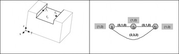
In the graphical representation of the topological and geometric entity graph, the nodes associated with the label ei* = (a2tpl, a3geo, a4geo) represent the topological and geometric relation of the faces, and the edges associated with the label eij = (a1tpl, a1geo, a2geo) represent the topological and geometric relation between a pair of faces (fi, fj). Figure 1 shows the representation of the “Slot” feature by the topological and geometric entity graph.

〈Slot〉 and its topologic and geometric entity graph.
2.2. Feature grammar
A feature language describes the generation of feature structures, joint elements, and attaching elements. A grammar provides the finite generic description of this language. Thus, we will focus on finding a feature grammar, which provides the generic and productive description of the feature language. In these conditions, a feature grammar can be defined as an 8-plet:

where VstructureT = {a, b, c · · ·} is the terminal vocabulary of structures, a nonempty finite set; Vjoint-tieT = {0, 1, 2 · · · j · · · m}, m ∈ N, is the terminal vocabulary of joint-tie elements, a nonempty finite set; VstructureN = {A, B · · · S · · ·} is the nonterminal vocabulary of structures, a nonempty finite set; Vjoint-tieN = {O, I, II, III · · · ∇, Λ} is the nonterminal vocabulary of joint-tie elements, a nonempty finite set; S, ∇, and Λ are the respective structure, joint, and connection axioms;

is a set of production rules; and

The production rules of the feature grammar have the following format:

where α is called the left-side component matrix, α = [αij], i = 1, j = 1; β is called the right-side component matrix, β = [βij], i = 1, j = 1, 2 · · · m; m is the number of components; Λα is called the left-side joint matrix, Γα = [Γαij], i = 1, 2 · · · n; j = 1; n is the number of attaching elements; Λβ is called the right-side joint matrix; Γβ = [Γβij], i = 1, 2 · · · n; j = 1, 2 · · · m; Δα is called the left-side tie-point matrix, Δα = [Δαij], i = 1, 2 · · · s; j = 1; s is the number of attaching elements; and Δβ is called the right-side tie-point matrix, Δβ = [Δβij], i = 1, 2 · · · s; j = 1, 2 · · · n.
There are three levels of production rules for the feature grammar. The first is the component level. These rules have the following formats:

or

where α ∈ VstructureN; β = v1, v2 · · · vj · · · vm; this matrix defines an order relation for these components; vj ∈ VstructureT ∪ VstructureN is a terminal or nonterminal structure called the component structure; and m is the number of structures.
The second level is the joint level. These rules have the following formats:

or

where yi is a joint element and tij is an attaching element of component j, defined according to the order in the right-side component matrix, that participates in forming the yi.
The third level is the connection level. These rules have the following formats:

or

where zi is an attaching element and tij is an attaching element of component j, defined according to the order in the right-side component matrix, that participates in forming the zi.
2.2.1. Conditional feature grammar
The feature grammar represents the purely syntactic side. It does not always allow the expression of the full complexity of structural relations between the primitive elements composing a feature. If a syntax rule must meet mandatory conditions before being applied, then a conditional feature grammar is defined as follows:

where Gfeature is the feature grammar,

are the three levels of semantic conditions, Ageo-tpl is the set of geometric and topological attributes, and Dgeo-tpl is the set of geometric and topological domains.
2.2.2. Fuzzy feature grammar
The elements of VstructureT = {a, b, c · · ·} that have a certain property, such as the nonexistence of virtual edges in a terminal a, make up a subset of VstructureT. If some elements of VstructureT do not have this property in an absolute manner, we may choose to indicate the extent to which each element has the property. Thus, we define a fuzzy subset of VstructureT. The fuzzy subset of VstructureT is defined by a membership function that associated with each element a of VstructureT, the extent (between 0 and 1) to which a is a member of this subset: μV : VstructureT → [0, 1]. In the presence of a rule in format [αij] → [βij], if [βij] is characterized by the membership function μβ = min(μv1, μv2 · · · μvj · · · μvn), and if the rule [αij] → [βij] is characterized by the membership function μα→β, then [αij] is defined by the membership function μα = min(μβ,μα→β). In this way we can determine the membership function of each nonterminal, and therefore, of axiom S. The feature grammar that benefits from these characteristics is called the fuzzy feature grammar.
2.3. Application
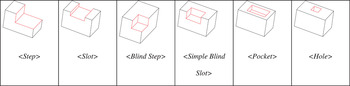
Given a set of features (Fig. 2)


A sample of the features in the set X. [A color version of this figure can be viewed online at www.journals.cambridge.org]
A feature can be represented by the selected topological and geometric entity graph, defined as follows:
Definition.
For two given sets

where F = {f1, f2 · · · fi · · · fm} is a set of faces; ei* = (a2tpl, a3geo) is an entity associated with each face fi (see Table 1);

where eij = (adjacents, concave, a2geo) (see Table 1), we call G = (F*, E) the selected topological and geometric entity graph. █
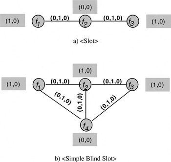
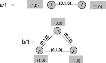
For example, the representation of 〈Slot〉 and 〈Simple Blind Slot〉 features by the selected topological and geometric entity graph is illustrated below (Fig. 3).

Selected topological and geometric entity graph.
The strength of feature grammars for feature representation will depend on terminal vocabulary definition. For terminals definition, we are using the following hypothesis: a terminal represents a robust connection between faces of features. The problem of robust connection in the selected topological and geometric entity graph can be seen as the obtaining of the full maximal subgraphs of this graph. It is equivalent to decomposition of one similarity relation into maximal similarity subrelations. Considering the set of features X, we have two terminals (Fig. 4).

Selected topological and geometric entity graph.
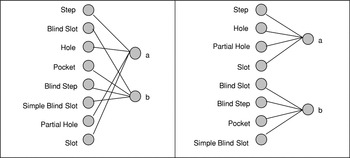
The relationship between the set of features and the set of terminals can be represented by the bipartite graph (Fig. 5). The graph decomposition yields two classes of features: C1X = {Step, Slot, Partial Hole, Hole} and C2X = {Blind Step, Simple Blind Slot, Blind Slot, Pocket}, corresponding to two classes of terminals: C1V = {a} and C2V = {b}.

The bipartite graph and its decomposition.
Two fuzzy feature grammars GFeatureC are inferred for the feature classes: C1X = {Step, Slot, Partial Hole, Hole} and C2X = {Blind Step, Simple Blind Slot, Blind Slot, Pocket}, respectively. For the first feature class, we have

The fuzzy feature grammar represents the syntactic and fuzzy aspect of features. Structures with the same syntax may represent features with different semantics. Thus, we can build the conditional and fuzzy feature grammar. In this case, the first level of production rules will be associated by conditions. For example, for the first level of production rules P6, we have the following semantic condition:
Structures b and A (on the right side of rule B → bA) are attached if the direction of the main vector A (on the right side) is the same as the direction of the vector

of b, where 1 and 2 represent the attaching elements of b.
The previous condition is used in a similar fashion for rules P1, P3, and P5. We will have the following condition for the first level of production rules:
The direction of the main vector of A (left side of the rule A → b) is initialized from

of b, where 1 and 2 represent the attaching elements of b.
There are no semantic conditions to be satisfied for the other rules.
For the second class, we have

The preceding production rules are associated by conditions similar to the previous class. In the case of this feature class, the mixed product

is considered. Thus, the structures (in the right part) are attached if the sign of the mixed product

does not change.
3. FEATURE RECOGNITION APPROACH
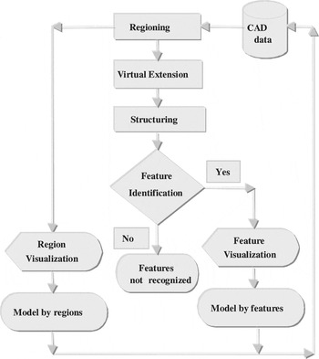
Using the principles discussed above, we have developed a new feature recognition approach. The flow chart in Figure 6 shows the main phases of this approach. The first phase, called regioning, consists of identifying the potential zones for the birth of features. The second phase, called virtual extension, consists of building links and virtual faces. The third phase, called structuring, consists of transforming the region into a structure compatible with the structure of the features represented by the feature grammar. The fourth phase, called identification, consists of identifying the features in these zones. The fifth phase, called, modeling, consists of representing the model either by regions or by features.

A flow chart of the feature recognition approach.
3.1. Regioning
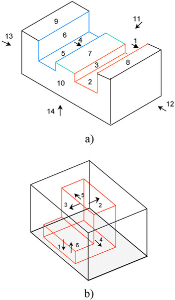
A region defines a potential area of a part where either canonical features or features in interaction may be recognized. During the interaction, features may have lost their concavity. As a result, some faces of features in interaction are not identified during the recognition phase. In this case, the potential region for feature recognition is expanded with concave border faces (local expansion principle). Thus, we can define a region of the part as a set of connected faces characterized by their concavity or their convexity that may be transformed into concavity. Furthermore, the interaction between features may produce neighboring regions that may be either adjacent or recoverable. If {R1 · · · Ri, Ri+1 · · · Rn} is a set of regions, then a macroregion R may be defined by grouping a set of neighboring regions (global expansion principle). For example, the part shown below (Fig. 7a) contains two regions. The first region comprises concave faces 1, 2, and 3 and convex face 7, which may be transformed to concave by the virtual extension toward face 1. The second region comprises concave faces 4, 5, and 6 and convex face 7. In this case, the convex face 7 can be transformed to concave by virtual extension toward face 6. These two regions share face 7. As a result, a macroregion is defined by 〈macroregion1〉 → 〈region11〉〈region12〉, where 〈region11〉 and 〈region12〉 are the first and second regions, respectively, of the first macroregion 〈macroregion1〉. The part in Marefat and Kashyap (1990; Fig. 7b) comprises a region that includes concave faces 1, 2, 3, 4, 5, and 6.

Examples of regions. [A color version of this figure can be viewed online at www.journals.cambridge.org]
Thus, the regioning procedure involves three subphases:
Subphase 1: Search for regions. The faces characterized by concavity are called the primary faces of the region. This phase consists of extracting the set of primary faces from the part and grouping them into regions.
Subphase 2: Local expansion. Based on the local expansion principle, the border faces, called the secondary faces, characterized by their convexity susceptible to be transformed into concavity, are assigned to the region in question.
Subphase 3: Creating macroregions. Based on the global expansion principle, regions are grouped together into macroregions.
3.2. Virtual extension
The faces in a region can be divided into three classes:
class 1: primary faces characterized by concavity only;
class 2: secondary faces characterized by convexity only; and
class 3: primary faces characterized by both concavity and convexity.
The first class concerns faces that resist to interaction. For example, faces 1, 2, and 3 and 4, 5, and 6 in the part in Figure 7a and faces 1, 2, 4, and 5 of the part in Figure 7b belong to this class. Despite the interaction, they kept their concavity characteristic. The second class concerns border faces. These convex faces probably lost all of their original concavity characteristics during the interaction. For example, face 7 (Fig. 7a) belongs to this class. The third class concerns primary faces, which probably lost their concavity characteristic during the interaction. For example, faces 3 and 6 (Fig. 7b) belong to this class. Thus, virtual extension consists of transforming the convex faces in the second and third classes into concave faces by generating virtual links. These links must meet the following conditions:
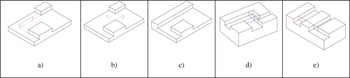
Condition 1: A pair of virtually extended faces belongs to a group of extended faces, if and only if their virtual adjacency is concave (Fig. 8a).

Illustrations of conditions. [A color version of this figure can be viewed online at www.journals.cambridge.org]
Condition 2: Given two convex edges ei and ej, faces X and Y are adjacent in ei and faces Z and V are adjacent in ej. If the virtual extension of faces X and Y and the virtual extension of faces Z and V create two edges, called virtual–virtual edges, then those edges are considered simultaneously (Fig. 8b).
Condition 3: If condition 2 is false, then between two adjacent convex faces, one and only one face can be virtually extended by forming an edge, called a virtual–real edge. This edge will jointly belong to the extended virtual face and the real virtually intersected face (Fig. 8c).
Condition 4: In a set, if each of the virtually extended faces form virtual–real edges, and if the virtual extensions intersect, then the selection of one of those faces penalizes the others (Fig. 8d).
Condition 5: The virtually extended face does not intersect the interior parts of the part faces (Fig. 8e).
The recomposition of the virtual face is a special case for the generation of virtual links. The interaction between the canonical features may break a face down into a group of small faces. Then those small faces may be unified into a virtual face. The minimal conditions for a group of faces to be unified are as follows (Marefat & Kashyap, 1990):
condition 1: the faces must have the same support surface, that is, the same equation;
condition 2: the normals of the faces must have the same directions; and
condition 3: the unified face must not intersect the interior parts of the part faces.
The first and second conditions show that the faces have the same geometry, while the third shows that the unified face cannot be destroyed by the other faces of the part. We define an order relation between the generation of virtual faces and virtual links: we first try to generate the virtual faces by unifying the groups of faces that meet the minimal conditions. If a virtual face is generated from the unification of a group of faces, then any face in that group must be virtually extended to form virtual links.
Example 2.
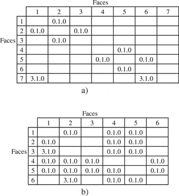
Given the parts in Figure 7a and b. For the part in Figure 7a, face 7 may be transformed into a concave face by generating virtual links with faces 6 and 1 matrix (Fig. 9a), while for the part in Figure 7b, face 3 and face 6 may be transformed into concave faces by generating virtual links with faces 1 and 2, respectively (Fig. 9b). █

A matrix representing the real or virtual concavity between faces.
3.3. Structuring
Structuring consists of converting the representation of macroregions (created by regioning) with virtual faces and links (created by virtual extension) into a structure compatible with the feature grammar definition. Structuring involves the following subphases described in Section 3:
subphase 1: searching for terminals and
subphase 2: creating canonical matrices (terminal matrix and joint matrix).
Example 3.
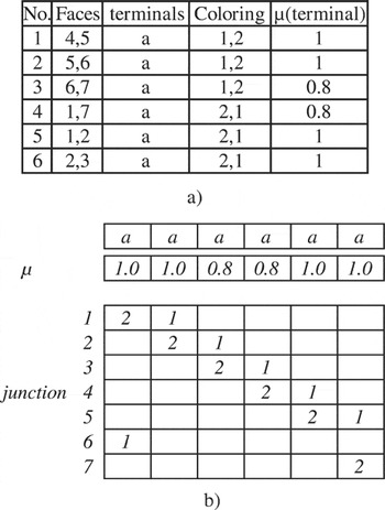
Given the part in Figure 7a and its matrix representing the relation between the faces (Fig. 9a). The terminals found and the canonical matrix are shown in Figure 10a and b.

The terminals and the canonical matrix of the recognized macroregion.
These terminals are type a. The terminal with faces 4 and 5 is colored first. Face 4 is colored with color 1 and face 5 with color 2. The terminal with faces 5 and 6 is colored second. As face 5 is colored with color 2 in a previous terminal, in this terminal it is colored with color 1. As a result, face 6 is colored with color 2. The membership function μV(a) associated with each terminal shows the extent to which that terminal is similar to terminal a. The terminal with a virtual concave edge is associated with μV(a) = 0.8. █
Example 4.
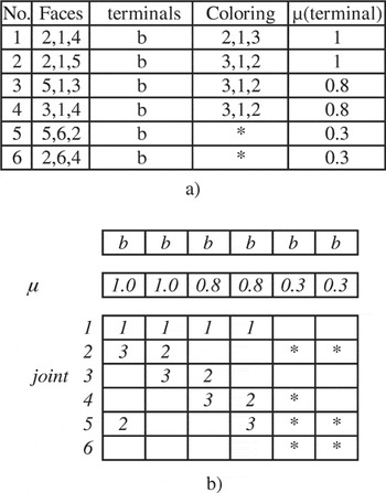
Given the part in Figure 7b and its matrix representing the relation between the faces (Fig. 9b). The terminals found and the canonical matrix are shown in Figure 11.

The terminals and the canonical matrix of the recognized macroregion.
The transformation of the maximum subrelations into colored terminals is shown in Figure 9b. These are type b terminals. For any terminal, the face considered as the base is colored with color 1. Thus, face 1 is colored with color 1. The other faces are colored using the same procedure. For example, the terminal with faces 1, 2, and 4 is colored first (face 1 is already colored). Face 2 is colored with color 2 and face 4 with color 3. The terminal with faces 1, 2, and 5 is colored second. As face 2 was colored with color 2 in a previous terminal, in this terminal it is colored with color 3. As a result, face 5 is colored with color 3. Thus, we continue coloring for all terminals. Terminals 5 and 6, with faces 6, 5, and 2 and 6, 2, and 4, respectively, are not colored because faces 5, 2, and 4 are already colored with colors 2 or 3. Furthermore, we consider that there is only one face with the characteristic base in a macroregion or a region. The membership function μV(a) associated with each terminal shows the extent to which the terminal is similar to terminal b. In the case of noncolored faces, this function takes the value of μV(b) = 0.3. The asterisk shows that terminals 5 and 6 participate in forming joints 2, 4, 5, and 6, but those terminals are not colored. █
3.4. Identification
The representation and the resolution of the recognition problem, for either canonical features or features in interaction, is shown in a state graph. Consider feature grammar G and a feature structure to be analyzed, represented by the canonical matrix (terminals matrix and joint matrix). A state is any possible rewriting of canonical matrices (terminal matrix and joint matrix) by one or more production rules of feature grammar G. States will constitute the nodes of the state graph. An arc will connect two states if we can pass from one state to another by a single application of a production rule of fuzzy feature grammar G or if the structure is updated after the recognition of a canonical feature in a region of features in interaction. The structure update consists of the following:
- virtually removing the faces and edges that are exclusively part of the recognized feature and considering the Virtual Extension conditions (union principle);
- reusing the faces shared by several features, knowing that if n virtual links are created to a real face, then that face will be shared by n + 1 features (sharing principle);
- creating new terminals knowing that if a face and/or edges are virtually erased in an order 3 terminal, then the terminal may be transformed into an order 2 terminal(s) (embedding principle).
Each arc is labeled with a letter representing either the production rule applied, or the notation for updating the structure. A state can be in one of the following conditions:
Condition 0: It is initial.
Condition 1: It has not been built yet.
Condition 2: It was just built by applying a production rule or by updating the structure.
Condition 3: It is a dead end. Some nodes are dead-end structures, for which no production rules are applicable.
Condition 4: It is terminal. A state is terminal if it represents either the recognized canonical feature, or features in interaction.
By applying the anchoring principle, virtual extension conditions, the sharing principle, the embedding principle, and the union principle, we have developed the following heuristic for identifying canonical features and/or features in interaction:
Step 1.
The initial structure represented by the canonical matrix defines the initial state (condition 0). The initial state is added to an ordered list of states according to the order relation of their structures.
Step 2.
If the list is empty, then failure; the procedure halts. Otherwise, we choose a state from the list using the following rule: last entered in the list, first out. It represents the current state wi. We remove it from the list and add it to the group of processed states W.
Step 3.
If the current state wi is a terminal state (condition 4), then success. The production rules can be found using the pointers created in step 5.
Step 4.
If production rules, set in an order relation, can be applied, then we develop the current state wi by creating the set of successor states Y, otherwise if a feature is recognized, then the structure can be updated (according to the virtual extension conditions, the sharing principle, the embedding principle, the union principle) by creating only a successor state in Y (condition 2), otherwise go to 2 (condition 3).
Step 5.
For all states Ywj, we put wj in list if it does not already belong there and if it does not belong to the group of processed states. If we put wj in the list, then we create a pointer wj to wi along with the production rule used.
Step 6.
Go to 2.
In the list, the last represents a maximal state. A state is maximal if it is hierarchically greater than the other states. Between two states at the same hierarchical level, the state from which a new state is formed and that is characterized by a value greater of the membership function μ is considered as a maximal state.
Example 5.
Given the part in Figure 7a, its canonical matrix (Fig. 10a) and the inferred conditional and fuzzy feature grammar GFeatureC for the feature class C1X = {Step, Slot, Partial Hole, Hole}. We find three 〈Slot〉 features, each of which comprises the following terminals, respectively: 5 and 6 for the first, 1 and 2 for the second, and 3 and 4 for the third. Each of these features is associated with the respective value of the membership function: μ = 1 for the first and second features and μ = 0.8 for the third. █
Example 6.
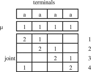
Given the part in Figure 7b, its canonical matrix (Fig. 10b) and the inferred conditional and fuzzy feature grammars GFeaturesC for the feature classes: C1X = {Step, Slot, Partial Hole, Hole} and C2X = {Blind Step, Simple Blind Slot, Blind Slot, Pocket}. The canonical matrix (Fig. 10b) represents the initial state. By successively applying rules P7, P6, P5, P1, P0 (developed on the right) in iterations 1, 2, 3, 4, and 5, we obtain the “Pocket” recognition feature with μPocket = 0.8. This feature comprises faces 1, 2, 3, 4, and 5. The structure is updated in the sixth iteration. According to Condition 3 of the virtual extension conditions, the virtual extension of face 3 penalizes the virtual extension of face 6. Thus, virtual edge 6, 2 will no longer exist in the fifth and sixth terminals. According to the embedding principle, the fifth terminal of type b comprising faces 2, 5, 6 will be transformed into two type a terminals comprising faces 2, 5 and 5, 6, respectively. Similarly, the sixth terminal of type b comprising faces 2, 4, 6 will be transformed into two type a terminals comprising faces 2, 4 and 6, 4, respectively. As both terminals comprising faces 2, 5 and faces 2, 4, respectively, are already used in the two terminals comprising faces (1, 2, 5) and faces (1, 2, 4), respectively, of the Pocket feature, then they will not be considered for the recognition of a new feature. Thus, the two terminals comprising faces 5, 6 and 6, 4, respectively, remain to be considered. According to the sharing principle, face 1 will be shared with other features because a virtual link is built to it. Faces 2 and 3 will be erased because these faces do not exist in the remaining terminals. As a result, according to the embedding principle, we will have two terminals comprising faces 1, 5 and 4, 1, respectively. Finally, we have four type a terminals, comprising faces (1, 5), (5, 6), (6, 4), (4, 1), respectively. The matrix in Figure 12 shows the updated structure.

The updated structure.
By applying in succession rules P7, P6, P5, P1, and P0 of the conditional and fuzzy feature grammar GFeatureC, inferred for class C1X = {Step, Slot, Partial Hole, Hole}, we finally recognize the 〈Hole〉 feature with μHole = 1. █
3.5. Modeling
The regioning phase transforms the representation B.Rep of the part into a representation by regions. The feature recognition in the identification phase transforms either the representation by macroregions into a representation by features (macroregions) or the representation by regions into a representation by features (regions). For example, for the part in Figure 7a we have


Equation (15) shows that the macroregion comprises three 〈Slots〉; Eq. (16) shows the faces that make up each 〈Slot〉.
4. APPLICATION
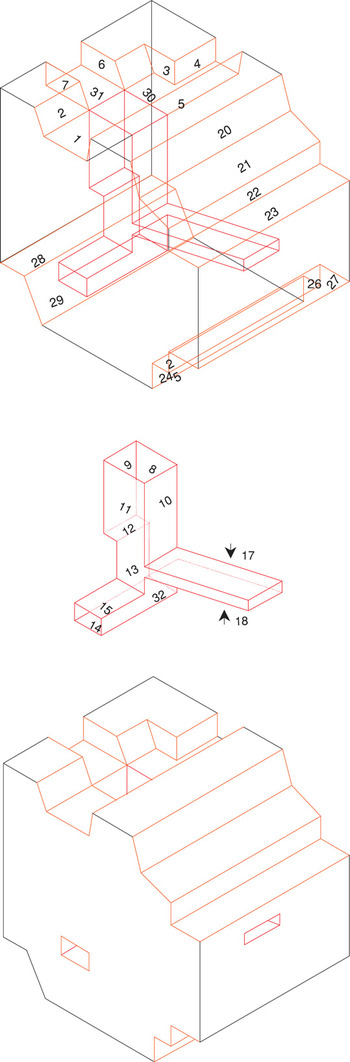
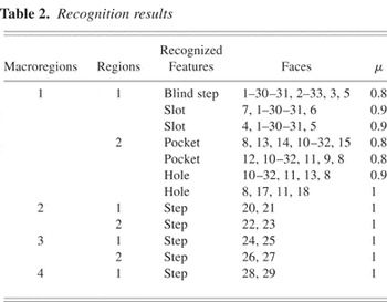
To give a comparative example, consider the part in Marefat and Kashyap (1990; Fig. 13). Table 2 gives the results of the feature recognition.

A part with features. [A color version of this figure can be viewed online at www.journals.cambridge.org]
Recognition results

If we compare our results with those of Marefat and Kashyap (1990), we can see several differences. For example, in the second region of the first macroregion, first we recognized the two pockets:

and then the two holes:

Thus, our approach implicitly follows the idea of extracting the volume of a recognized feature. In the approach of Marefat and Kashyap (1990), the recognition of the preceding two pockets had no influence on subsequent feature recognitions. Thus, after recognizing those two pockets, in Marefat and Kashyap (1990), another pocket defined by faces 14, 13, 11, 10–32, and 8 was recognized. The feature modeling system software was developed in a CAD environment (CATIA from Dassault Systems on an IBM RS 6000 workstation).
5. CONCLUSIONS
This paper proposed an approach for recognizing either canonical features or features in interaction. The proposed recognition approach included various phases. The first phase, regioning, consisted of identifying the potential zones for the birth of features. The creation of macroregions, as a subphase in regioning, can be used later to define relations between features. The second phase, virtual extension, consisted of building links and virtual faces. Here we used a possibilistic approach, given the problem for recognizing features in interaction. The third phase, structuring, consisted of transforming the region into a structure compatible with the structure of the features represented by the fuzzy feature grammar. The fourth phase, identification, consisted of identifying the features in these zones. The heuristic attempts to generate a set of possible solutions based on the fuzzy feature grammar. We must stress that the number of solutions can be reduced if we consider a predefined knowledge context. The fifth phase, modeling, consisted of representing the model by features. The feature modeling system software using this approach is implemented in the CATIA CAD–CAM environment. The proposed approach provides a global framework for the feature recognition problem. Feature recognition is highly dependent on the representation by the feature grammar. In cases where the features are not formalized by a grammar and as a result are not recognized, the approach proposes potential regions by differentiating macroregions and the constituent regions. Recognized features are used for various applications.
References
REFERENCES
Ansaldi, S.,
de Floriano, L., &
Falcadino, B.
(1985).
An edge–face relational scheme for boundary
representation.
Computer Graphics Forum
4(4),
319–332.Google Scholar
Bond, A.H. &
Chang, K.J.
(1988).
Feature based process planning for machined parts.
Proc. ASME Int. Computers in Engineering Conf.,
Vol. 1, pp.
571–576,
San Diego, CA.
Bronsvoort, W. &
Jansen, F.W.
(1993).
Feature modelling and conversion—key concepts to concurrent
engineering.
Computers in Industry
21,
61–68.Google Scholar
Choi, B.K.,
Barabash, M.M., &
Anderson, D.C.
(1988).
Automatic recognition of machined surfaces from a 3-D solid
model.
CAD
20(2),
58–64.Google Scholar
De Martino, T. &
Gianini, F.
(1994).
The role of feature recognition in the future CAD systems.
Proc. IFIP Int. Conf. Feature Modelling and Recognition in
Advanced CAD/CAM Systems, pp.
343–356,
Valenciennes, France.
Falcidieno, B. &
Gianini, F.
(1989).
Automatic recognition and representation of shape-based features in
a geometric modelling system.
Computers Vision, Graphics and Image Proceedings
48,
92–123.Google Scholar
Henderson, M.R.
(1994).
Manufacturing feature identification.
Artificial Neural Networks for Intelligent Manufacturing, pp.
229–264.
London:
Chapman & Hall.
Henderson, M.R. &
Anderson, D.C.
(1984).
Computer recognition and extraction of form features: a CAD/CAM
link.
Computers in Industry
5,
329–339.CrossRefGoogle Scholar
Joshi, S. &
Chang, T.S.
(1988).
Graph based heuristics for recognition of machined features from 3-D
solid model.
CAD
20,
58–66.Google Scholar
Kim, Y.S.
(1992).
Recognition of form features using convex decomposition.
CAD
24(9),
461–476.Google Scholar
Kim, Y.S. &
Wilde, D.J.
(1992).
A convex decomposition using convex hulls and local cause of its
non-convergence.
ASME Journal of Mechanical Design
114,
459–467.Google Scholar
Laako, T. &
Mäntylä, M.
(1993).
Feature modelling by incremental feature recognition.
CAD
25(8),
479–492.Google Scholar
Li, R.K.
(1988).
A part-feature recognition system for rotational parts.
International Journal of Product Research
26(9),
1451–1475.Google Scholar
Marefat, M. &
Kashyap, R.L.
(1990).
Geometric reasoning for recognition of three dimensional object
features.
Transactions of the 8th Army Conf. Applied Mathematics and
Computing, pp.
705–731.
Menon, S. &
Kim, Y.S.
(1994).
Cylindrical features in form feature recognition using convex
decomposition.
Proc. IFIP Int. Conf. Feature Modelling and Recognition in
Advanced CAD/CAM Systems, pp.
295–314,
Valenciennes, France.
Srinavasan, R.,
Liu, C.R., &
Fu, S.K.
(1985).
Extraction of manufacturing details from Geometric models.
Computers and Industrial Engineering
9,
125–134.CrossRefGoogle Scholar
Woo, T.
(1982).
Feature extraction by volume decomposition.
Proc. CAD/CAM Technology in Mechanical Engineering
Conf., pp.
76–94.
Cambridge, MA:
MIT.
Domains and associated attributes
〈Slot〉 and its topologic and geometric entity graph.
A sample of the features in the set X. [A color version of this figure can be viewed online at www.journals.cambridge.org]
Selected topological and geometric entity graph.
Selected topological and geometric entity graph.
The bipartite graph and its decomposition.
A flow chart of the feature recognition approach.
Examples of regions. [A color version of this figure can be viewed online at www.journals.cambridge.org]
Illustrations of conditions. [A color version of this figure can be viewed online at www.journals.cambridge.org]
A matrix representing the real or virtual concavity between faces.
The terminals and the canonical matrix of the recognized macroregion.
The terminals and the canonical matrix of the recognized macroregion.
The updated structure.
A part with features. [A color version of this figure can be viewed online at www.journals.cambridge.org]
Recognition results
 You have
Access
- 9
- Cited by