Introduction
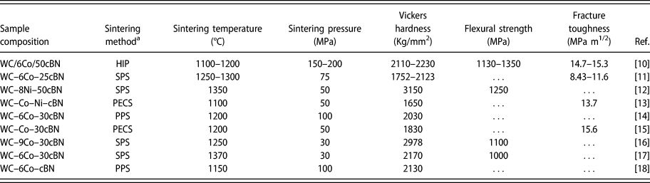
Cubic boron nitride (cBN) is the second hardest material and has superior chemical and hot stability relative to diamond [Reference Vel, Demazeau and Etourneau1, Reference Monteiro, Skury, de Azevedo and Bobrovnitchii2]. Because of its outstanding abrasive wear resistance and superior stability, it has been widely used in the manufacturing industries as drilling, cutting, and grinding tool materials [Reference Ding, Xu, Shen, Fu, Xiao, Su and Xu3, Reference Cook and Bossom4, Reference Ronning, Feldermann and Hofsäss5, Reference Yaman and Mandal6], although its mechanical strength and toughness are somewhat inferior. WC-based cemented carbides, also widely used for cutting and drilling tools, consist of a hard WC phase and metallic binder phase such as Co, Ni, Fe, or their mixture, and possess a unique combination of high strength and toughness [Reference Locci, Orru and Ca7, Reference Ren, Miao and Peng8, Reference Prakash9]. Cemented carbides are the most favorable materials for drill-bit inserts for mining, tunneling, and geothermal well applications. Considering the complementarity of their mechanical properties, it is proposed that the composites of cBN and cemented carbides may possess excellent comprehensive mechanical performance. Thus, developing composites of cBN dispersed cemented carbides has attracted much interest in the last decades [Reference Martínez and Echeberria10, Reference Yaman and Mandal11, Reference Rong, Peng, Ren, Wang, Fu, Qi and Miao12, Reference Wang, Matsumaru, Yang, Fu and Ishizaki13, Reference Rasiński and Michalski14, Reference Wang, Qin, Jin, Yang and Ishizaki15, Reference Mao, Zhang, Zhang, Tang, Gan and Zhang16, Reference Mao, Ren, Gan, Zhang, Zhang and Tang17, Reference Michalski, Cymerman and Rasiński18], which can be seen in Table I.
State of the art on cBN dispersed cemented carbide composites in the literatures.

a HIP: hot isostatic pressing; SPS: spark plasma sintering; PECS: pulse electric current sintering; PPS: pulse plasma sintering.
It is difficult to fabricate such composites by conventional sintering methods because the addition of cBN significantly reduces sinterability. Moreover, the added cBN is prone to transform from cBN to the low-hardness hexagonal boron nitride (hBN) at the normally applied sintering temperature (∼1350 °C) [Reference Vel, Demazeau and Etourneau1, Reference Martínez and Echeberria10, Reference Wang, Matsumaru, Yang, Fu and Ishizaki13, Reference Michalski, Cymerman and Rasiński18, Reference Solozhenko, Turkevich and Holzapfel19, Reference Hotta and Goto20]. Therefore, many studies report processes to solve these problems (also see Table I). In 2007, Martínez et al. [Reference Martínez and Echeberria10] fabricated a nearly fully dense cBN dispersed cemented carbide composite by hot isostatic sintering with no phase transformation of cBN into hBN at a temperature between 1100 and 1200 °C under a pressure between 150 and 200 MPa. It was later reported that nearly fully dense cBN dispersed cemented carbide composites could be obtained below 1300 °C by electric field–assisted fast sintering techniques, such as spark plasma sintering (SPS) and pulse electric current sintering (PECS) [Reference Yaman and Mandal11, Reference Rong, Peng, Ren, Wang, Fu, Qi and Miao12, Reference Wang, Matsumaru, Yang, Fu and Ishizaki13, Reference Rasiński and Michalski14, Reference Wang, Qin, Jin, Yang and Ishizaki15, Reference Mao, Zhang, Zhang, Tang, Gan and Zhang16]. However, in such samples, the bonding strength between the cBN particles and cemented carbides matrix was poor because of the high interfacial energy and low surface wettability between them.
Coating the cBN particles with a metal is one of the main methods to improve the interfacial bonding strength between the cBN particles and metal matrix because the metallic layers on the cBN particles can efficiently decrease the interfacial energies and improve the surface wettability between [Reference Zhang, Tu and Goto21, Reference Kitiwan, Ito, Zhang and Goto22, Reference Zhang, Tu and Goto23]. For example, Wang et al. [Reference Wang, Qiu, Sun and Yin24, Reference Wang, Lei, Ruan and Dong25, Reference Yang, Gong, Yue and Chu26] indicated that a Ti layer could improve the bonding strength between cBN particles and metal matrix. Ding et al. [Reference Ding, Xu, Shen, Fu and Xiao27] reported that the Ti layer in the interfacial region between the active brazing alloy and cBN particles could react with the cBN grains to form TiB2 and TiN, resulting in an improvement of the bonding strength between the cBN and metal matrix. However, the effect of Ti-coated cBN (cBN@Ti) particles on the microstructure and mechanical properties of WC–Ni cemented carbides has never been reported.
The purpose of this work was to develop composites of cBN@Ti dispersed WC–Ni cemented carbides by the SPS method and to investigate the sintering behavior, phase composition, microstructure, mechanical properties, and grinding behavior during cutting rocks of the cBN@Ti dispersed cemented carbide composites.
Results and discussion
Sintering behavior
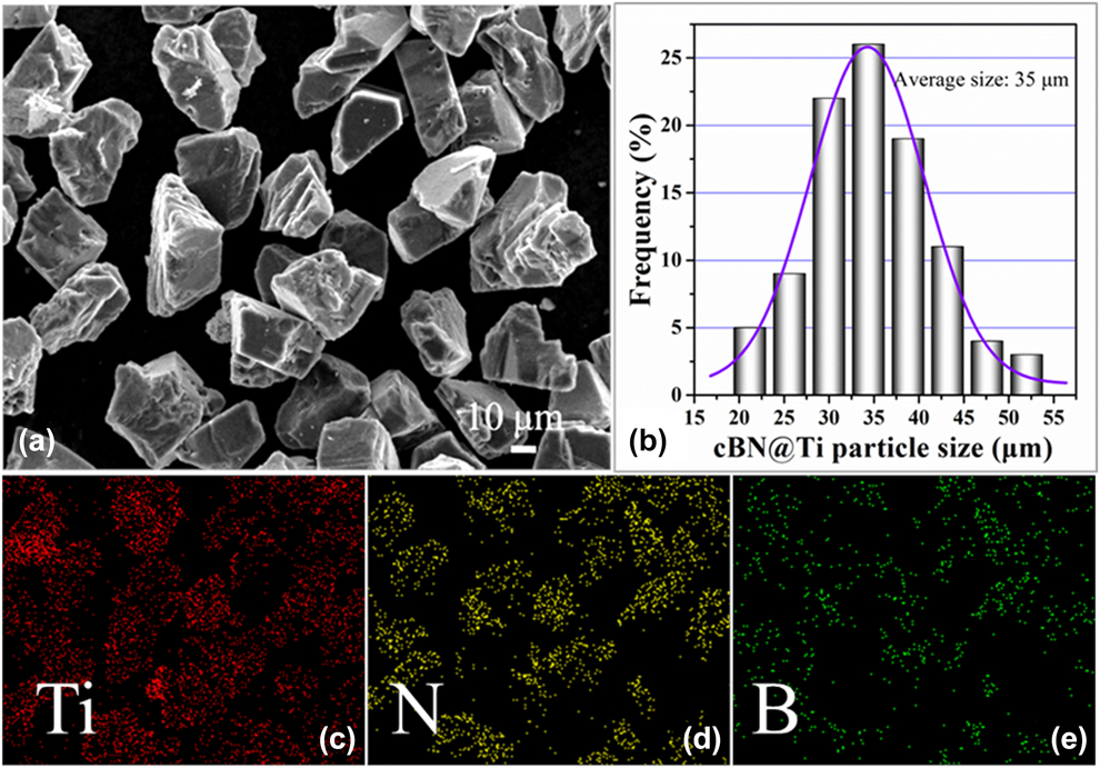
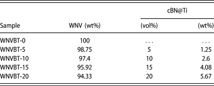
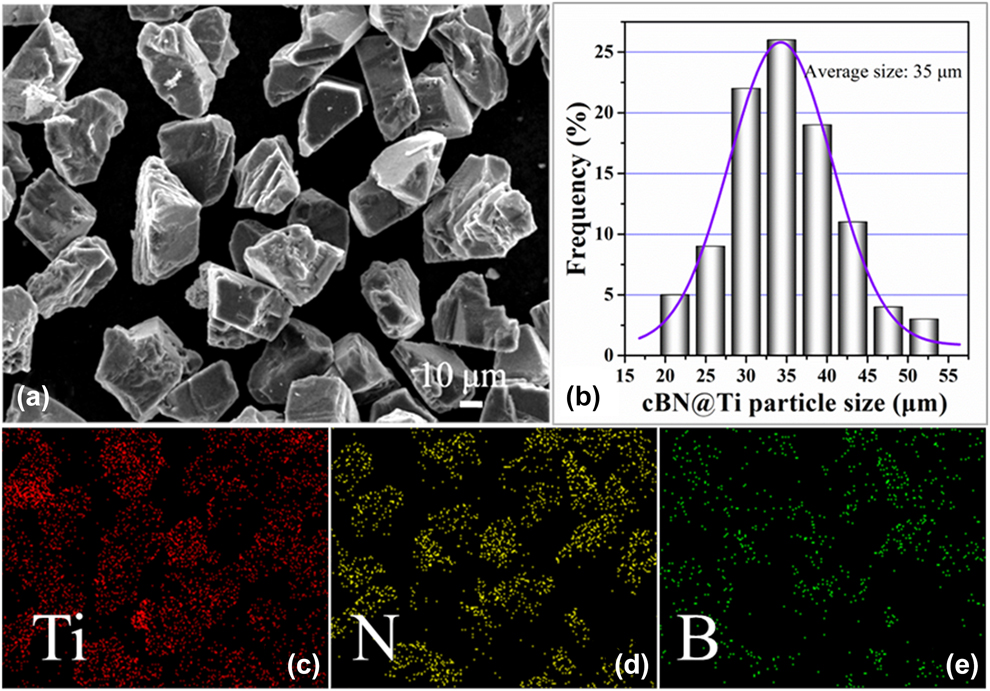
The morphology, grain size distribution, and corresponding elemental composition of the obtained cBN@Ti particles are shown in Fig. 1. As is seen in Fig. 1, the obtained cBN@Ti particles are triangular, and the Ti layer is uniformly coated on the cBN particles. The size distribution of the cBN@Ti particles follows the normal distribution with a mean size of about 35 μm. The proposed composites were fabricated by adding different fractions of the cBN@Ti particles (0–20 vol%) into a cemented carbide matrix of 91 wt% WC + 8 wt% Ni + 1 wt% VC (WNV). The composites are abbreviated as WNVBT with nominal compositions listed in Table II.
Typical SEM image (a), grain size distribution (b), and the corresponding EDX mapping patterns of Ti (c), N (d), and B (e) elements in the Ti-coated cBN particles.
Nominal compositions of the designed WNVBT composites with different fractions of the cBN@Ti particles.

The shrinkage displacement and furnace vacuum are recorded online during sintering the WNVBT composites, and their variation curves with the sintering time are shown in Fig. S1. It is seen that the shrinkage process during the sintering can be divided into two stages: rapid shrinkage stage from about 800 to 1300 °C and constant stage at the holding temperature of 1300 °C. During the initial temperature increase, the samples shrink slowly, presenting a shrinkage displacement of about 0.125 mm in each 100 °C increase in sintering temperature. During this stage, absorbed gases and moisture in the powders evaporated and surface oxides are to form the corresponding gases. Therefore, the furnace vacuum presents a significant reduction in this stage as shown in Fig. S1, which is ranging from 15 to 90 Pa. In the rapid shrinkage stage, the samples shrink quite quickly. The maximum shrinkage displacement reaches 1.54 mm in each 100 °C increase in sintering temperature. During this stage, the reduction of furnace vacuum is not remarkable, ranging from 15 to 30 Pa. The samples complete densification by ∼1250 °C, and the furnace vacuum gradually decreases to 15 Pa.
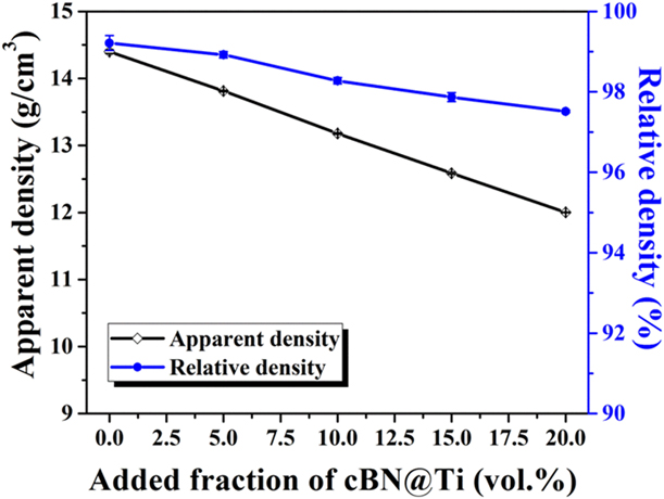
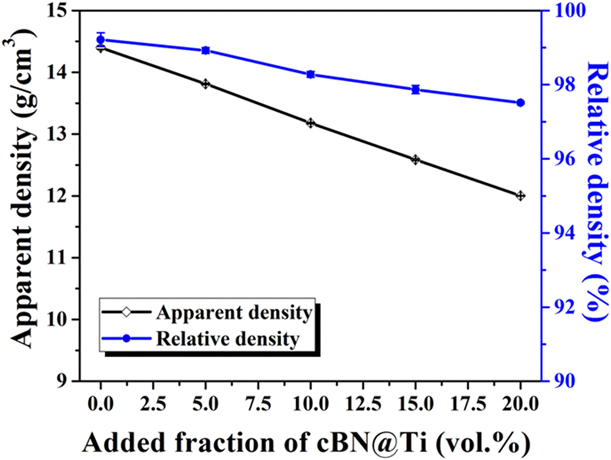
Figure 2 illustrates the apparent and relative densities of the obtained samples as a function of cBN@Ti content. As the added amount of the cBN@Ti increases, the apparent density of the samples gradually decreases from 14.4 to 12.1 g/cm3. The relative density of the samples gradually decreases with increasing cBN@Ti content, ranging from 99.1 to 97.5%. As shown in Fig. 1, the mean size of the added cBN@Ti particles is about 35 μm, which is much larger than those of the matrix WC (about 0.6 μm) and Ni (about 0.7 μm). As is well known, the specific surface energy of the powders contributes much to the sintering kinetics of the samples. With the increase in volume fraction of the added cBN@Ti in the composites, the total specific surface area of the powders decreases, which would result in the reduction of the overall specific surface energy. Furthermore, such large particles are known to constrain densification [Reference Sudre and Lange28]. Consequently, the relative density of the samples gradually decreases.
Apparent and relative densities of WNVBT composites as a function of cBN@Ti content.
Phase composition and microstructure
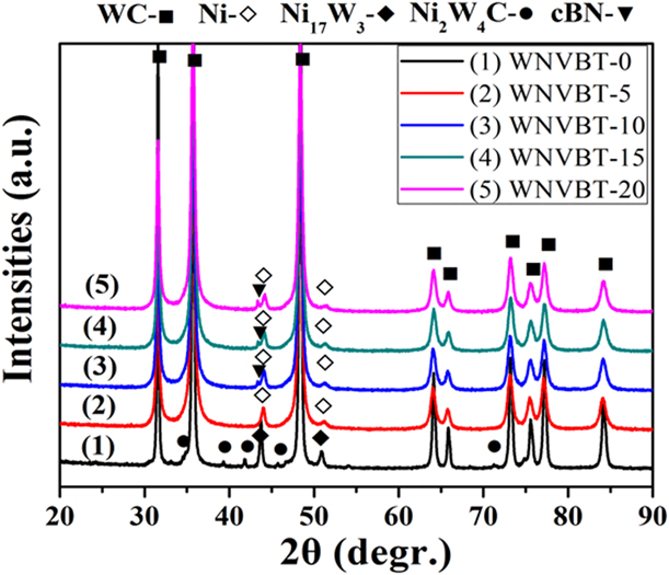
Figure 3 exhibits the X-ray diffraction (XRD) patterns (color online) of the cBN@Ti–WC–Ni composites. The WC phase (PDF card: 65-8828) could be obviously identified in all samples. In the sample without cBN@Ti, no Ni phase was observed but a Ni17W3 phase (PDF card: 65-4828) and a Ni2W4C phase (PDF card: 20-0796) were identified. As is known, the surface oxides on the WC particles could be reduced during SPS because of the decarburization of WC. As a result, the Ni17W3 and Ni2W4C phases would be formed in this sample. With the addition of cBN@Ti, the decarburization of WC was effectively suppressed. Thus, no Ni-containing compounds such as the Ni17W3 and Ni2W4C phases were identified. Within the detection limit of XRD, the cBN phase (PDF card: 25-1033) is detected when >10 vol% is added. However, hBN peaks, which are usually observed in similar samples reported in the literature [Reference Vel, Demazeau and Etourneau1, Reference Martínez and Echeberria10, Reference Wang, Matsumaru, Yang, Fu and Ishizaki13, Reference Michalski, Cymerman and Rasiński18], were not identified, but the intensity of the cBN peaks gradually increases with increasing cBN@Ti content. This result confirms that no obvious cBN to hBN phase transformation happens during the SPS of the present cBN@Ti–WC–Ni composites.
XRD patterns of the obtained WNVBT composites as a function of cBN@Ti content.
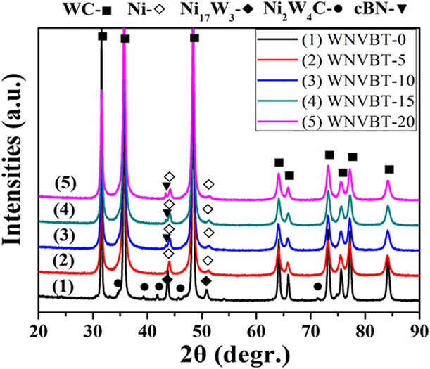
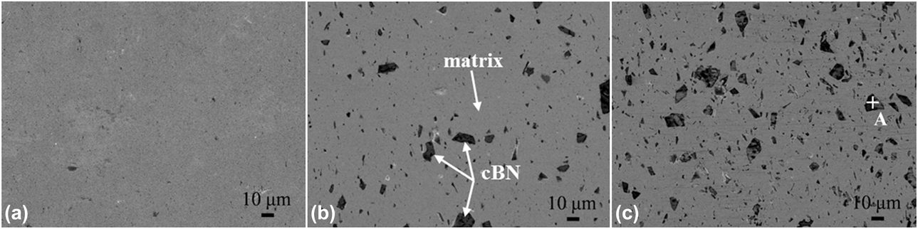
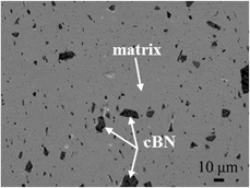
Figure 4 displays typical scanning electron microscopy (SEM) images on the polished surface of the obtained composites with different fractions of cBN@Ti particles. Compared with the sample without cBN@Ti, the composite samples exhibit a remarkable contrast in the images. Some homogeneously distributed particles (black in the images) can be observed in the samples. Moreover, energy dispersive X-ray (EDX) analysis reveals that these particles are composed of N and B. In combination with the XRD results, it is easily concluded that the morphology and composition of the added cBN@Ti particles are maintained during the designed sintering.
Typical SEM images of the polished surface of the samples with different fractions of the cBN@Ti particles: (a) 0, (b) 10, and (c) 20 vol%.

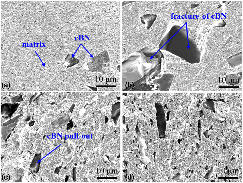
Figure 5 presents typical SEM images of the fractured surface of the obtained samples with different fractions of cBN@Ti. From this figure, cBN particles (black in the images) can be clearly distinguished. With increasing cBN@Ti content, the particles tend to homogeneously distribute in the samples. Moreover, from these images, it is seen that most of the broken cBN particles generated during the sample preparation present a transgranular fracture mechanism, implying a relatively strong bonding between the cBN particles and cemented carbide matrix, which is beneficial for the improvement in the mechanical properties of the samples. With increasing cBN@Ti content, the porosity of the cemented carbide matrix increases slightly [see Figs. 5(c) and 5(d)].
Typical fractured surface of composites with different cBN@Ti contents: (a) 5, (b) 10, (c) 15, and (d) 20 vol%.
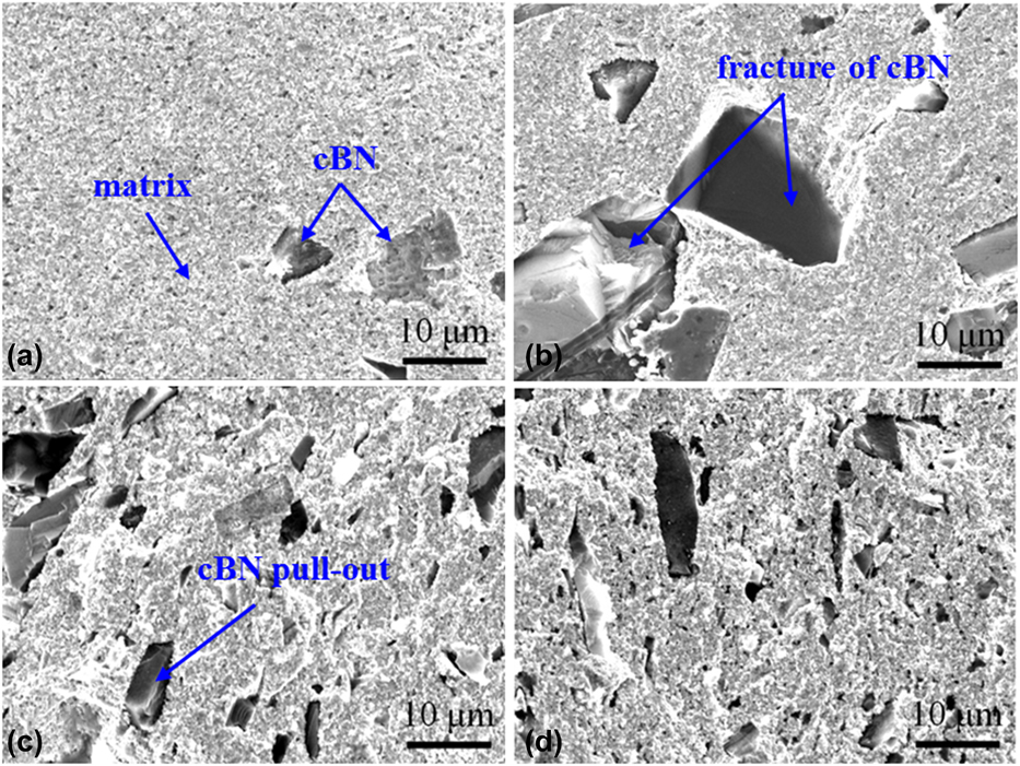
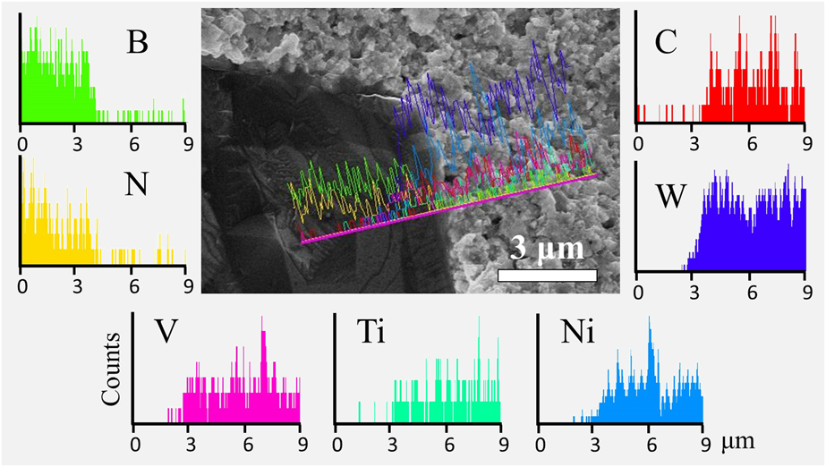
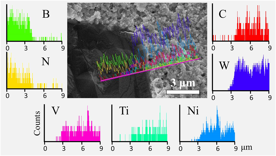
Figure 6 shows a typical SEM image and the corresponding line-scanning patterns (color online) on the fractured surface of the sample with 10 vol% cBN@Ti. The SEM image reveals that there is no obvious gap between the cBN particles and WC–Ni matrix, implying strong bonding between them. Moreover, the line-scanning patterns indicate that there is a Ti-rich interface between the cBN particles and the WC–Ni matrix, which would improve the bonding strength between the cBN particles and WC–Ni matrix, supporting the conclusion on the strong bonding between them.
Typical SEM image and the corresponding line scanning patterns on the fractured surface of composite with 10 vol% cBN@Ti.
Mechanical properties
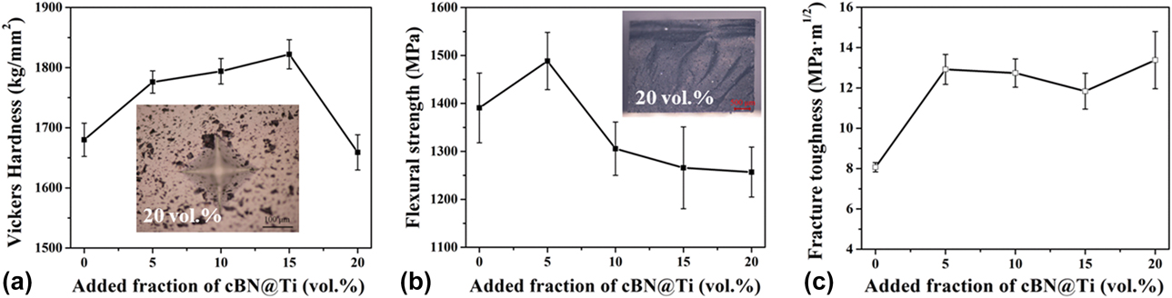
Figure 7 illustrates the Vickers hardness (HV10), three-point flexural strength and Palmqvist indentation fracture toughness of the samples with different fractions of the cBN@Ti particles. As shown in this figure, with the increase in the added amount of the cBN@Ti, the Vickers hardness and flexural strength of the obtained WNVBT composites initially increased and then decreased, reaching the maximum value of 1820 HV10 for the sample with 15 vol% cBN@Ti and 1500 MPa with 5 vol% cBN@Ti, respectively. As the cBN@Ti content increases, the Palmqvist indentation fracture toughness increases at the beginning, gradually reaching almost a constant.
Vickers hardness (a), flexural strength (b), and fracture toughness (c) of WNVBT composites with different cBN@Ti contents. The inset in (a) shows a typical indentation image after the measurement of hardness, and the one in (b) displays a typical image on the macroscopic fracture surface for the composite with 20 vol% cBN@Ti.
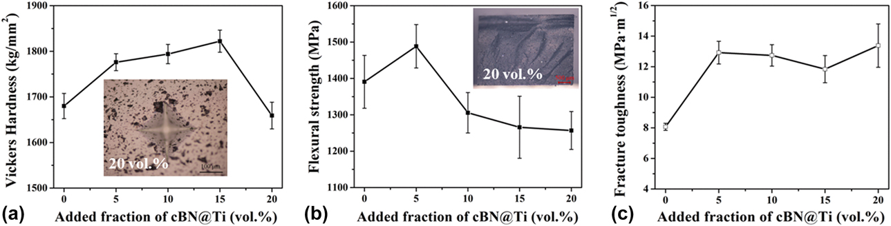
As seen in Fig. 5, the WC grain size has no obvious change with the increase in the added fraction of the cBN@Ti particles. Hence, the evolution of the sample hardness mainly relies on the variations of their densification and the amount of cBN@Ti. Because the hardness of the cBN@Ti is much higher than that of the cemented carbide matrix, it would lead to an increase in the hardness of the samples. However, because of the decrease in density, the hardness of the sample with 20 vol% cBN@Ti decreases [Fig. 7(a)].
The three-point flexural strength of the present composites is closely correlated with the elastic modulus and the density of the samples. As the cBN@Ti content increases, the flexural strength gradually decreases because of the decreased sample densification and correspondingly increased critical flaws. However, as shown in Fig. 7(b), the flexural strength improved slightly with 5 vol% cBN@Ti. The higher elastic modulus of the added cBN than the WC matrix should be responsible for it. According to the mixture rules, the elastic modulus of the present WNVBT composites is higher than that of the sample without cBN@Ti, when the constituents in the samples have a strong bonding strength. For the sample with 5 vol% cBN@Ti, the reduction of its relative density is not obvious, although the elastic modulus increases significantly. Resultantly, it yields the increase in the flexural strength of this sample.
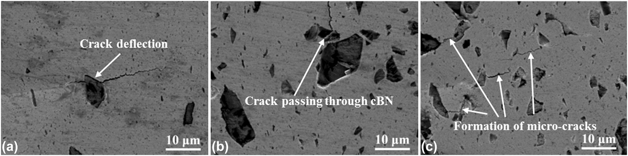
The fracture toughness increased from 8 to 13 MPa m1/2 with increasing cBN@Ti particles, gradually reaching almost a constant with >5.0 vol% cBN@Ti [Fig. 7(c)]. Figure 8 presents typical SEM images of the crack propagation on the polished surface of the obtained WNVBT samples. In this figure, the crack deflection led by the large, coarse cBN particles and the crack passing through the cBN particles can be clearly observed. Both processes would consume the crack propagation energy, resulting in the improvement of the fracture toughness. However, as the cBN@Ti content increases, the relative densities of the samples gradually decrease. As a result, a lot of micro-cracks are formed around the cBN particles [see Fig. 8(c)], which will limit the further improvement of the fracture toughness. Within the designed fraction of cBN@Ti, the fracture toughness of the samples reaches approximately a constant.
Crack propagation on the polished surface of typical samples: (a) WNVBT-5, (b) WNVBT-10, and (c) WNVBT-20.

Grinding behavior
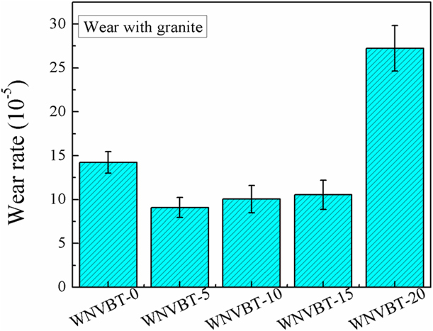
Figure 9 shows the wear rate of the obtained WNVBT composites after cutting 6.41 cm3 of granite. It is seen that, as the cBN@Ti content increases, the wear resistance of the composites significantly improves but drastically degrades with 20 vol% cBN@Ti. The samples with 5–15 vol% cBN@Ti present the minimum value of the wear rate (about 8 × 10⁻⁵), and the sample with 20 vol% cBN@Ti shows the maximum value of the wear rate (about 27 × 10−5). The decrease in the wear rate should be mainly attributed to the much harder cBN phase in the samples.
The wear rate of WNVBT composites after cutting 6.41 cm3 of granite.
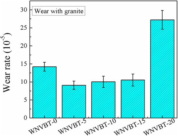
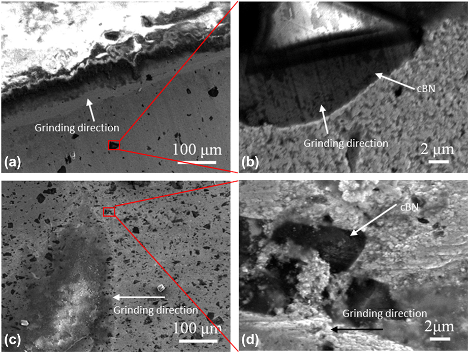
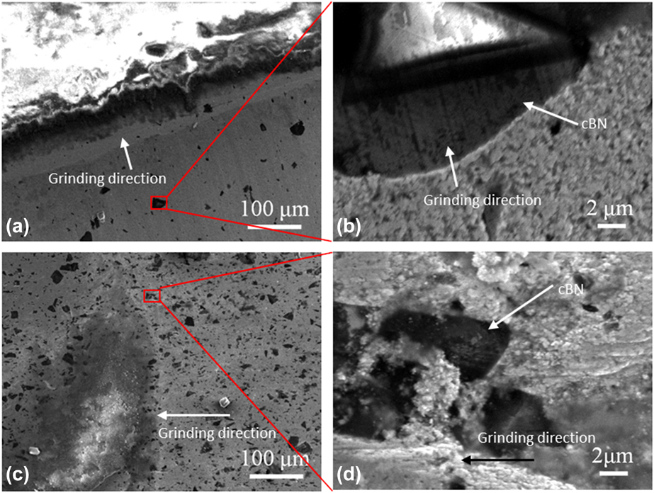
Figure 10 shows typical SEM images on the worn surface of the samples with 5 and 20 vol% of the cBN@Ti particles. As shown in this figure, the cemented carbide matrix of the sample with 5 vol% cBN@Ti is strongly bonded, whereas the sample with 20 vol% cBN@Ti has significantly higher porosity. During cutting the granite sample, the faster abrasion of the matrix protruded the cBN particles. For the samples with 5–15 vol% cBN@Ti, the strongly bonded cBN particles resist the grinding of WC grains, thus resulting in the reduction of the wear rate. This conclusion is well supported by the obviously observed grinding cracks on the cBN particles [see Fig. 10(b)]. However, for the sample with 20 vol% cBN@Ti, the protruding cBN particles are prone to pull-out during the cutting process and increase the wear of the sample because of the lower density of the matrix [see Fig. 10(d)].
Typical SEM images on the worn surface of WNVBT composites after cutting the granite sample: (a, b) WNVBT-5 and (c, d) WNVBT-20.
Conclusions
Composites of 0–20 vol% Ti-coated cBN particles dispersed WC–Ni were successfully fabricated at 1300 °C by SPS without the phase transformation from cBN to hBN.
(1) A Ti-rich transition layer could be observed between the cBN particles and cemented carbide matrix. The cBN particles were distributed homogeneously and were strongly bonded with the matrix. As the added fraction of the cBN@Ti increases, the sinterability decreases somewhat with a gradual decrease in relative density of the composite from 99.2 to 97.5%.
(2) With increasing cBN@Ti content, the Vickers hardness and flexural strength of the samples initially increase and then decrease, reaching the maximum value of 1820 HV10 for the sample with 15 vol% cBN@Ti and 1500 MPa with 5 vol% cBN@Ti, respectively. For the samples with more than 5 vol% cBN@Ti, the fracture toughness K IC increases to about 13 MPa m1/2.
(3) With increasing cBN@Ti content, the wear rate of the composites decreases first and then increases. For the samples with 5–15 vol% cBN@Ti, the protruding cBN particles improve their wear resistance, but for the ones with more cBN@Ti, the pull-out of cBN particles and the lower density aggravate their abrasion.
Experimental procedure
Sample preparation
The commercially purchased submicron-sized WC (∼0.6 μm, ≥99.5%), Ni (∼0.7 μm, ≥99.9%) and VC (∼0.7 μm, ≥99%) were used as the matrix powders. The micron-sized cBN particles were used as the additive.
Before the fabrication of the proposed composites, the cBN particles were coated with a thin Ti layer (no more than 1 μm) by vacuum vapor deposition through slowly evaporating the mixture of TiCl3 and TiH2 powders. During the processing, the cBN particles were first buried in the mixture of TiCl3 and TiH2 powders. After the samples were loaded into the vacuum furnace, the vacuum system worked to pump off the residual gases to a vacuum degree of 10−3 Pa, and then the heating system was operated. For the deposition, the temperature was kept at about 600 °C and the working pressure of the furnace was 1–10 Pa. After heating, the furnace was cooled down naturally to room temperature and the furnace was pumped off again to the vacuum degree of 10−3 Pa. Finally, the as-indicated micron-sized cBN particles were obtained.
The WNVBT composites were fabricated according to the processing strategy as presented in Fig. S2. First, the raw WC, Ni, and VC powders in the designed mass ratio of 91:8:1 were mixed in alcohol and ball-milled in a high-energy attrition mill (model: SY-1; Tencan Powder Company, Changsha, China) for 48 h with Φ 5 mm YG-6 cemented carbide balls as the grinding media. For the milling, the rotational speed was 200 rpm. Then, in each portion of the milled powder mixture slurry, the designed fraction of the cBN@Ti particles was added and mixed fully for additionally 2 h in a very low rotational speed of about 20–30 rpm. After that the resultant slurries were dried in a vacuum oven for about 24 h below 60 °C. After drying, the powder chunks were ground and sieved into fine powders. After sieving, the obtained powders were sintered by an SPS apparatus (model: SPS-1050T; Sumitomo Coal Mining Company, Ltd., Tokyo, Japan under a vacuum of no more than 15 Pa. The sintering temperature, axial pressure, heating rate, and holding time were 1300 °C, 50 MPa, 100 °C/min, and 5 min, respectively. After sintering, the samples were cut, ground, and polished into the final test shapes.
Materials characterization
The phase composition of the obtained composites was determined by X-ray diffraction (XRD; model: D8-Advance; Bruker, Germany) with Cu Kα radiation in a continuous scanning mode at a speed of 5°/min. The microstructure and chemical composition on the fractured and polished surfaces of the samples were examined by scanning electron microscopy (SEM; model: JSM-7001F; JEOL. Ltd., Japan) equipped with an EDX spectrometer.
The shrinkage of the samples during SPS was evaluated by recording the displacement of the lower punch of the SPS apparatus after the uniaxial pressure reached 50 MPa. The apparent density of the obtained samples was measured by the Archimedes method according to the international standard ISO18754. The theoretical density was evaluated by using the nominal mass fractions of WC, Ni, VC, and cBN@Ti in the samples. The relative density of the acquired samples is defined as the percentage of the apparent density to their corresponding theoretical density. The hardness (HV10) was measured on a Vickers hardness tester (model: VH-5; Everone Precision Instruments Co., Ltd., Shanghai, China) with an indentation load of 98 N for 15 s. The Palmqvist indentation fracture toughness was calculated by measuring the crack length near the indent resulted from the hardness test, according to the following Shetty equation [Reference Wang, Jiang, Chen and Bai29]:
 $${K_{{\rm{IC}}}} = 0.0889\sqrt {{\rm{HV}}} \sqrt {{P \over {\sum\limits_{i = 1}^4 {{l_i}} }}} \quad ,$$
where HV is the Vickers hardness (N/mm2) of the samples, P is the load (N) during indentation, and l i is the length of the ith crack emerging from the hardness indent (μm).
The wear behavior of the obtained composites was evaluated by cutting granite rocks, which was characterized on a modified CS6140A screw-cutting lathe as introduced in Ref. Reference Yan, Yue, Meng, Lin, Wu and Wang30. The wear testing system and its schematic diagram are shown in Fig. S3. A granite rock with the compressive strength of 129.6 MPa and drillability grade of level IX was used as the cut body. The wear rate (W R) was defined as the ratio between the worn volume of the cutting tool material (ΔV M) and the worn volume of the cut rock (ΔV R), as expressed by the following equation:
 $${W_{\rm{R}}} = {{\Delta {V_{\rm{M}}}} \over {\Delta {V_{\rm{R}}}}} = {{{{\Delta m} / \rho }} \over {\pi \cdot D \cdot {a_{\rm{p}}} \cdot l}} = {{\Delta m} \over {\pi \cdot D \cdot {a_{\rm{p}}} \cdot l \cdot \rho }}\quad ,$$
where Δm (g) denotes the worn mass of the composite, ρ (g/cm3) is the density of the composite, D (mm) is the diameter of the rock cylinder, a p (mm) is the cutting depth, f (mm/r) is the feed rate, and l (mm) is the cutting stroke. The test parameters in the grinding test included a p = 0.2 mm, f = 0.06604 mm/r, l = 100 mm, and the rotational speed n = 280 rpm. After each test, the Δm and D values were measured. For each sample, the grinding test was repeated three times to calculate the mean wear rate.
Supplementary material
To view supplementary material for this article, please visit https://doi.org/10.1557/jmr.2019.308.
Acknowledgments
This work was supported by the National Natural Science Foundation of China (Grant No. 51905299), the Project funded by China Postdoctoral Science Foundation (Grant No. 2018M640120), Grand Survey on Land and Nature Sources of China sponsored by China Geological Survey (Grant No. 1212010916026), and the Fundamental Research Funds for the Central Universities.