1 Introduction
An external antenna structure at the edge of a tokamak fusion device excites radio frequency (RF) waves for heating and/or current drive. These waves propagate through a turbulent scrape-off layer before they reach their intended target, in the plasma core. The scrape-off layer is populated by filaments and blobs (see Krasheninnikov Reference Krasheninnikov2001; Grulke Reference Grulke, Terry, Labombard and Zweben2006; Myra et al. Reference Myra, D’ Ippolito, Stotler, Zweben, Leblanc, Menard, Maqueda and Boedo2006; Myra, Russell & D’Ippolito Reference Myra, Russell and D’Ippolito2006; Zweben Reference Zweben, Boedo, Grulke, Hidalgo, Labombard, Maqueda, Scarin and Terry2007; Pigarov Reference Pigarov, Krasheninnikov and Rognlien2012), where the plasma electron density differs from that in the background environment. As a result, the plasma permittivity of these structures is different from the background plasma’s permittivity. For this reason, the characteristic properties of the incident radio frequency waves can change during their transition through the scrape-off layer, so that the RF waves can be modified by these turbulent structures.
The study of the effects that the propagation through a different dielectric medium (such as a filament) has on the incident wave’s properties could be based on the geometric optics approximation (see Hizanidis Reference Hizanidis, Ram, Kominis and Tsironis2010). However, there is a limitation to the geometric optic’s applicability: the electrons density of the filament must be close to the ambient electrons density, so that the absolute value of the relative density contrast between the filament and the ambient electron density is very small (see Ram Reference Ram, Hizanidis and Kominis2013, Reference Ram and Hizanidis2016), which is not the case: a typical experimental range of values is from
 $5$
to
 $100\,\%$
. Thus, there is a physics reason to derive a more general approach with validity in a much larger domain.
In this article, Maxwell’s equations are used to derive a full-wave analytical model for the scattering process of RF waves by cylindrical density filaments. The case of spherical density fluctuations has already been studied (see Ram Reference Ram and Hizanidis2013). Moreover, elongated cylindrical density filaments have also been studied (see Ram Reference Ram and Hizanidis2016) but the axis of the cylinder was assumed to be aligned with the total magnetic field. At this point, it should be noted that the total magnetic field in a tokamak plasma is the result of the toroidal magnetic field component (which is externally imposed) and the poloidal magnetic field component (which is generated by the plasma current). The amplitude ratio, of the poloidal magnetic field component to the toroidal magnetic field component, is known as the tangent of the magnetic field pitch angle (see Prisiazhniuk Reference Prisiazhniuk2017). This angle is not necessarily small, as there are recorded experimental values of up to
 $40^{\circ }$
(e.g. as referred to in Taylor Reference Taylor, Efthimion, Leblanc, Carter, Caughman, Wilgen, Preinhaelter, Harvey and Sabbagh2005, for the National Spherical Torus Experiment – NSTX). The combination of toroidal and poloidal magnetic field components creates finally, in general, a helical total magnetic field line structure and the magnetic field lines do not lie on a flux surface but are open field lines. In the presence of this total magnetic field, the cylindrical filaments created in the plasma are transported radially (towards the plasma edge, see Krasheninnikov Reference Krasheninnikov2001; Grulke Reference Grulke, Terry, Labombard and Zweben2006), without having any physics reason for being continually rotated in the way that would be needed to keep their orientation parallel to the helical total magnetic field line. Furthermore, there is experimental evidence (e.g. see Grulke Reference Grulke, Terry, Cziegler, Labombard and Garcia2014, referring to the fusion device Alcator C-Mod) proving that the filaments are nearly, but not perfectly, aligned with the total magnetic field; thus, there is a need to study the scattering effects in the general case, when the cylinder axis is not parallel to the total magnetic field.
The study described here is a generalization of a previous work (Ram Reference Ram and Hizanidis2016): the major magnetic field component is assumed to be along the axis of the cylindrical filament, but in this article the presence of a magnetic field component with a different orientation is also considered on the scattering of RF waves, so that the physics of the scattering phenomenon changes. When there is only the major component of the magnetic field, the component of the wave vector along the magnetic field
 $k_{\Vert }$
is preserved; i.e. waves inside the filament and the scattered waves have the same
 $k_{\Vert }$
as the incident plane wave. In the presence of another magnetic field component with general orientation this is no longer true, while only the component of the wave vector along the cylinder axis
 $k_{z}$
is preserved. The scattered wave can have a spectrum of
 $k_{\Vert }$
which depends on the angle of inclination between the axis of the filament and the direction of the total magnetic field. In effect, the scattering process broadens the
 $k_{\Vert }$
spectrum of the waves transmitted towards the core plasma. This, in turn, can affect the power deposition profile of the RF waves in the core of the plasma.
So, by having no limitation for the total magnetic field to be aligned with the axis of the cylinder, it is considered to be at an angle
 $\unicode[STIX]{x1D719}_{0}$
with respect to the axis. It must be noted that for the purposes of this study, the toroidal plasma is assumed to have a large aspect ratio, approximated by an infinitely extended slab, where the filaments exist and the magnetic field is homogeneous. In addition, the axis of the cylindrical filament is assumed to have infinite length, so that the edge effects can be ignored. The background ambient plasma as well as the filament are assumed cold and uniform with the respective permittivities being those of a cold plasma. First, in addition to refraction, also reflection, diffraction and shadowing are incorporated. Moreover, the fluctuations can couple power to other plasma waves (e.g. an ordinary mode wave can activate an extraordinary mode one and vice versa). In addition, the scattered waves propagate in all radial directions of the cylindrical filament and not only forward to the core, so that there exists redirection of the incident power.
Another simplification made in this study is that the fluctuations in the scrape-off layer are static: in fact, the fluctuations are moving. According to experimental results, the speed of the toroidal propagation of the fluctuations around the tokamak is approximately
 $5\times 10^{3}~\text{m}~\text{s}^{-1}$
, approximately five orders of magnitude below the RF wave propagation speed, which is nearly the well-known speed of light in a vacuum. That renders our simplification a valid assumption.
Concerning the structure of this paper, in order not to overwhelm readers with the algebra – which the authors consider necessary and relevant to the complete formulation – the following paragraphs outline the purpose of each section.
Section 2 starts with a geometrical aspect: two coordinate systems are defined. The first coordinate system is with respect to the ambient magnetic field in which the background plasma and the filament are embedded. The second coordinate system is defined with respect to the axis of the filament. In a previous paper (Ram Reference Ram and Hizanidis2016) the two coordinate systems were the same. The incident wave is best described in the first coordinate system. The wave fields inside the cylindrical filament, and the scattered fields are best described in the second coordinate system. For an overall compatible description, the transformation between the two coordinate systems is set-up in this section. Also, the incident wave is expressed in terms of the exponential dyadic involving the complete set of the vector cylinder functions.
Next, in § 3 Maxwell’s equations are used to derive the appropriate fourth-order cold plasma dispersion relation, which is set-up in both coordinate systems. The two natural modes that satisfy the dispersion relation are categorized within and outside the filament. Section 4 sets up the polarization of each of the two natural modes.
Given the form of the incident and scattered fields that exist in the background plasma, and the confined fields inside the filament, a self-consistent solution is obtained by satisfying the boundary conditions at the surface of the filament. It is assumed that there are no free charges and currents on the surface. Then the requisite boundary conditions follow from Faraday’s and Ampere’s equations. These are set-up in § 5. An important consequence of the boundary conditions is that, for all waves, the parallel to the magnetic field component of the wave vector (
 $k_{\Vert }$
) is not the same if the axis of the filament is not aligned with the direction of the magnetic field. This leads to the generalization of previous formulations of scattering theory (Ram Reference Ram and Hizanidis2016).
Section 6 sets up the form of the electric and magnetic fields and the Poynting flux in the forward (to the plasma core) direction, that form the basis of our computations. The numerical results are given in § 7 and cover a variety of different cases: magnetic field inclination with respect to the filament axis varies while the magnitude of the magnetic induction is kept the same
 $B=4.5T$
, different filament radii are simulated, the relative density contrast between the filament and the ambient electrons density varies also and the polarization mode of the incident wave can be an O-mode or X-mode. In § 8, the main conclusions of this study are presented.
2 Main assumptions and the geometry
The total magnetic field lines are considered to be parallel to the
 $(z{-}x)$
-plane with
 $z$
being the axis of the cylindrical filament and
 $\unicode[STIX]{x1D719}_{0}$
being the angle of the total magnetic field lines (axis
 $z^{\prime }$
) with respect to
 $z$
(see figure 1). In the cylinder (i.e. filament) reference system, let
 $\unicode[STIX]{x1D711}_{k}$
be the azimuthal angle of a respective plane wave component.
The cylinder has radius
 $a$
and it’s length,
 $L$
, is assumed to be much larger than
 $a$
(
 $a/L\ll 1$
). Thus, we assume that it has infinite length in order to exclude edge effects. Note that for the case of a finite RF beam incident at the midlength of a long filament, this approximation is adequate. The electron density inside the cylinder, as well as the electrons density outside, is considered as homogeneous and the plasma is assumed to be cold. There is no limitation for the ratio of these two different densities.
Let
 $\unicode[STIX]{x1D64D}_{y}(\unicode[STIX]{x1D719}_{0})$
be the rotation matrix (see appendix A.1) which transforms from the Cartesian filament reference system to the magnetic field (axis
 $z^{\prime }$
) primed reference system. The magnetic field is assumed as homogeneous throughout this work. On the other hand, let
 $\unicode[STIX]{x1D64D}_{c}(\unicode[STIX]{x1D711}_{k})$
be defined as the rotation matrix (see appendix A.2) which transforms from the cylindrical reference system where a plane wave vector is defined, to the Cartesian filament reference system.
Magnetic field and cylinder coordinate systems.

The wave vector of an individual plane wave (either incident or scattered, etc.) is denoted as
 $\boldsymbol{k}$
and the position vector in the filament reference system is denoted as
 $\boldsymbol{r}$
. By normalizing these two vectors to the dimensionless ones
 $\boldsymbol{n}\equiv \boldsymbol{k}c/\unicode[STIX]{x1D714}$
and
 $\unicode[STIX]{x1D746}\equiv \boldsymbol{r}\unicode[STIX]{x1D714}/c$
with
 $c$
being the speed of light in vacuum and
 $\unicode[STIX]{x1D714}=2\unicode[STIX]{x03C0}f$
being the angular frequency (while
 $f$
is the frequency). The dot product of
 $\boldsymbol{n}\boldsymbol{\cdot }\unicode[STIX]{x1D746}$
(which is the normalized
 $\boldsymbol{k}\boldsymbol{\cdot }\boldsymbol{r}$
) can be calculated in cylindrical coordinates as:
 $$\begin{eqnarray}\boldsymbol{n}\boldsymbol{\cdot }\unicode[STIX]{x1D746}=\left(\begin{array}{@{}ccc@{}}\unicode[STIX]{x1D712} & \unicode[STIX]{x1D713} & \unicode[STIX]{x1D701}\end{array}\right)\left(\begin{array}{@{}c@{}}n_{x}\\ n_{y}\\ n_{z}\end{array}\right),\end{eqnarray}$$
where
 $\unicode[STIX]{x1D712}$
,
 $\unicode[STIX]{x1D713}$
and
 $\unicode[STIX]{x1D701}$
are the normalized coordinates
 $x$
,
 $y$
and
 $z$
of the position vector on the cylindrical reference system, respectively. According to (A 8a,b
)
 $$\begin{eqnarray}\boldsymbol{n}\boldsymbol{\cdot }\unicode[STIX]{x1D746}=\left(\begin{array}{@{}c@{}}\unicode[STIX]{x1D70C}\cos \unicode[STIX]{x1D711}\,\,\unicode[STIX]{x1D70C}\sin \unicode[STIX]{x1D711}\,\,\unicode[STIX]{x1D701}\end{array}\right)\unicode[STIX]{x1D64D}_{c}(\unicode[STIX]{x1D711}_{k})\left(\begin{array}{@{}c@{}}n_{\unicode[STIX]{x1D70C}}\\ 0\\ n_{z}\end{array}\right)=n_{\unicode[STIX]{x1D70C}}\unicode[STIX]{x1D70C}\cos (\unicode[STIX]{x1D711}-\unicode[STIX]{x1D711}_{k})+n_{z}\unicode[STIX]{x1D701},\end{eqnarray}$$
where
 $\unicode[STIX]{x1D711}$
and
 $\unicode[STIX]{x1D711}_{k}$
are the azimuthal angles between the
 $x$
-axis and
 $\unicode[STIX]{x1D746}$
and
 $\boldsymbol{n}$
, respectively. From now on, the subscript index ‘
 $0$
’ is used when referring to the incident wave (single plane wave), for which one may write:
 $$\begin{eqnarray}\boldsymbol{n}_{0}\boldsymbol{\cdot }\unicode[STIX]{x1D746}=n_{0\unicode[STIX]{x1D70C}}\unicode[STIX]{x1D70C}\cos (\unicode[STIX]{x1D711}-\unicode[STIX]{x1D711}_{0k})+n_{0z}\unicode[STIX]{x1D701}.\end{eqnarray}$$
The respective incident RF wave, propagating in the background plasma and impinging on the cylindrical filament, is therefore:
 $$\begin{eqnarray}\boldsymbol{E}_{I}(\unicode[STIX]{x1D746})=\boldsymbol{E}_{0}(\boldsymbol{n}_{0},\unicode[STIX]{x1D714})\exp (i\boldsymbol{n}_{0}\boldsymbol{\cdot }\unicode[STIX]{x1D746}).\end{eqnarray}$$
The normalized to its amplitude (
 ${\mathcal{E}}_{0}$
) incident electric field intensity is:
 $$\begin{eqnarray}\frac{\boldsymbol{E}_{I}(\unicode[STIX]{x1D746})}{{\mathcal{E}}_{0}}=\frac{\boldsymbol{E}_{0}(\boldsymbol{n}_{0},\unicode[STIX]{x1D714})}{{\mathcal{E}}_{0}}\exp (\text{i}\boldsymbol{n}_{0}\boldsymbol{\cdot }\unicode[STIX]{x1D746})=\boldsymbol{e}_{0}^{P}\exp \{\text{i}[n_{0\unicode[STIX]{x1D70C}}\unicode[STIX]{x1D70C}\cos (\unicode[STIX]{x1D711}-\unicode[STIX]{x1D711}_{0}+n_{0z}\unicode[STIX]{x1D701})]\},\end{eqnarray}$$
with
 $$\begin{eqnarray}\boldsymbol{e}_{0}^{P}\equiv \frac{\boldsymbol{E}_{0}(\boldsymbol{n}_{0},\unicode[STIX]{x1D714})}{{\mathcal{E}}_{0}}\end{eqnarray}$$
being the electric field polarization vector of the incident wave. Similarly, one may define the respective polarization for a plane wave mode ‘
 $k$
’ as:
 $$\begin{eqnarray}\boldsymbol{e}_{k}^{P}\equiv \frac{\boldsymbol{E}_{k}(\boldsymbol{n}_{k},\unicode[STIX]{x1D714})}{{\mathcal{E}}_{0}}.\end{eqnarray}$$
In terms of the exponential dyadic involving the vector cylinder functions
 $\boldsymbol{m}_{n}$
,
 $\boldsymbol{n}_{n}$
and
 $\boldsymbol{l}_{n}$
(see appendix B) in the cylinder frame of reference (convenient), one has
 $$\begin{eqnarray}\displaystyle \boldsymbol{e}_{k}^{P}\exp (\text{i}\boldsymbol{n}_{k}\boldsymbol{\cdot }\unicode[STIX]{x1D746}) & = & \displaystyle \boldsymbol{e}_{k}^{P}\boldsymbol{\cdot }\mathop{\sum }_{n=-\infty }^{n=\infty }\left[\boldsymbol{a}_{kn}\boldsymbol{m}_{n}(n_{k\unicode[STIX]{x1D70C}}\unicode[STIX]{x1D70C},n_{kz}\unicode[STIX]{x1D701},\unicode[STIX]{x1D711})+\boldsymbol{b}_{kn}\boldsymbol{n}_{n}(n_{k\unicode[STIX]{x1D70C}}\unicode[STIX]{x1D70C},n_{kz}\unicode[STIX]{x1D701},\unicode[STIX]{x1D711})\right.\nonumber\\ \displaystyle & & \displaystyle \left.+\,\boldsymbol{c}_{kn}\boldsymbol{l}_{n}(n_{k\unicode[STIX]{x1D70C}}\unicode[STIX]{x1D70C},n_{kz}\unicode[STIX]{x1D701},\unicode[STIX]{x1D711})\right]\!,\end{eqnarray}$$
where the vectorial coefficients
 $\boldsymbol{a}_{n}$
,
 $\boldsymbol{b}_{n}$
and
 $\boldsymbol{c}_{n}$
in the dyadic of the exponential can be calculated on the basis of the completeness property of the vector cylindrical functions and the index ‘
 $k$
’ is general (when ‘
 $0$
’, it refers to the incident field). Thus, in the Cartesian coordinate system of the cylinder (the respective component is indicated by a superscript):
 $$\begin{eqnarray}\left(\begin{array}{@{}c@{}}\hat{\boldsymbol{x}}\\ \hat{\boldsymbol{y}}\\ \hat{\boldsymbol{z}}\end{array}\right)\text{e}^{\text{i}\unicode[STIX]{x1D746}\boldsymbol{\cdot }\boldsymbol{n}_{k}}=\mathop{\sum }_{n=-\infty }^{n=\infty }\left[\left(\begin{array}{@{}c@{}}a_{kn}^{x}\\ a_{kn}^{y}\\ a_{kn}^{z}\end{array}\right)\boldsymbol{m}_{n}+\left(\begin{array}{@{}c@{}}b_{kn}^{x}\\ b_{kn}^{y}\\ b_{kn}^{z}\end{array}\right)\boldsymbol{n}_{n}+\left(\begin{array}{@{}c@{}}c_{kn}^{x}\\ c_{kn}^{y}\\ c_{kn}^{z}\end{array}\right)\boldsymbol{l}_{n}\right],\end{eqnarray}$$
where after calculations, the coefficients are:
 $$\begin{eqnarray}\displaystyle & \displaystyle \left(\begin{array}{@{}c@{}}a_{kn}^{x}\\ a_{kn}^{y}\\ a_{kn}^{z}\end{array}\right)=\left(\begin{array}{@{}c@{}}-\!\sin \unicode[STIX]{x1D711}_{k}\\ \cos \unicode[STIX]{x1D711}_{k}\\ 0\end{array}\right){\displaystyle \frac{\text{i}^{n+1}\text{e}^{-\text{i}n\unicode[STIX]{x1D711}_{k}}}{n_{k\unicode[STIX]{x1D70C}}}} & \displaystyle\end{eqnarray}$$
 $$\begin{eqnarray}\displaystyle & \displaystyle \left(\begin{array}{@{}c@{}}b_{kn}^{x}\\ b_{kn}^{y}\\ b_{kn}^{z}\end{array}\right)=-\text{i}^{n}{\displaystyle \frac{n_{kz}}{n_{k}n_{k\unicode[STIX]{x1D70C}}}}\text{e}^{-\text{i}n\unicode[STIX]{x1D711}_{k}}\left(\begin{array}{@{}c@{}}\cos \unicode[STIX]{x1D711}_{k}\\ \sin \unicode[STIX]{x1D711}_{k}\\ -{\displaystyle \frac{n_{k\unicode[STIX]{x1D70C}}}{n_{kz}}}\end{array}\right) & \displaystyle\end{eqnarray}$$
 $$\begin{eqnarray}\displaystyle & \displaystyle \left(\begin{array}{@{}c@{}}c_{kn}^{x}\\ c_{kn}^{y}\\ c_{kn}^{z}\end{array}\right)=-\text{i}^{n+1}{\displaystyle \frac{\text{e}^{-\text{i}n\unicode[STIX]{x1D711}_{k}}}{n_{k}^{2}}}\left(\begin{array}{@{}c@{}}n_{k\unicode[STIX]{x1D70C}}\cos \unicode[STIX]{x1D711}_{k}\\ n_{k\unicode[STIX]{x1D70C}}\sin \unicode[STIX]{x1D711}_{k}\\ n_{kz}\end{array}\right). & \displaystyle\end{eqnarray}$$
3 Propagation of RF waves in plasma and the dispersion relation
3.1 The electric field in general
For a cold plasma, the Faraday equation combined with the Ampere equation in the Fourier domain renders (see Ioannidis Reference Ioannidis, Ram, Hizanidis and Tigelis2017):
 $$\begin{eqnarray}\unicode[STIX]{x1D700}_{0}\unicode[STIX]{x1D735}\times \unicode[STIX]{x1D735}\times \boldsymbol{E}(\unicode[STIX]{x1D746})-\left({\displaystyle \frac{\unicode[STIX]{x1D714}}{c}}\right)^{2}\boldsymbol{D}(\unicode[STIX]{x1D746})=0.\end{eqnarray}$$
Note that Maxwell’s equations are expressed in cylindrical coordinates with respect to the flux tube, in order to maximally exploit the cylindrical geometry. It is assumed that the plasma equilibrium is time independent and the linearized perturbed electromagnetic fields have a time dependence of the form
 $\text{e}^{-\text{i}\unicode[STIX]{x1D714}t}$
, with
 $t$
being the time. In normalized wave vector representation:
 $$\begin{eqnarray}\boldsymbol{E}(\unicode[STIX]{x1D746})=\iiint \boldsymbol{E}(\boldsymbol{n})\exp (\text{i}\boldsymbol{n}\boldsymbol{\cdot }\unicode[STIX]{x1D746})\,\text{d}^{3}n.\end{eqnarray}$$
The combination of equations (3.1) and (3.2) leads to:
 $$\begin{eqnarray}\boldsymbol{D}(\unicode[STIX]{x1D746})=\unicode[STIX]{x1D700}_{0}\iiint \unicode[STIX]{x1D646}\boldsymbol{\cdot }\boldsymbol{E}(\boldsymbol{n})\exp (\text{i}\boldsymbol{n}\boldsymbol{\cdot }\unicode[STIX]{x1D746})\,\text{d}^{3}n,\end{eqnarray}$$
where
 $\unicode[STIX]{x1D646}$
is the permittivity tensor (see Stix Reference Stix1992). By substituting the (3.2) and (3.3) into (3.1), it is:
 $$\begin{eqnarray}\unicode[STIX]{x1D63F}(\boldsymbol{n})\boldsymbol{\cdot }\boldsymbol{E}=0,\end{eqnarray}$$
with
 $\unicode[STIX]{x1D63F}(\boldsymbol{n})=\unicode[STIX]{x1D646}+(\boldsymbol{n}\boldsymbol{n}-\unicode[STIX]{x1D644}n^{2})$
being the dispersion tensor. For non-trivial solutions of the electric field intensity, the determinant of the dispersion tensor must be zero. The latter requirement, the dispersion relation in other words, selects the sub-manifold in the Fourier space, where non-trivial electric field Fourier components exist. That is:
 $$\begin{eqnarray}\det [\unicode[STIX]{x1D63F}(\boldsymbol{n})]=0\end{eqnarray}$$
or, in a cylindrical frame of reference for the wave vector with a
 $z$
-axis aligned with the cylinder’s
 $z$
-axis:
 $$\begin{eqnarray}\det [\unicode[STIX]{x1D63F}(n_{k\unicode[STIX]{x1D70C}},n_{kz},\unicode[STIX]{x1D711}_{k})]=0,\end{eqnarray}$$
which will lead to a fourth-order equation with respect to
 $n_{k\unicode[STIX]{x1D70C}}$
.
3.2 The dispersion relation derivation
In the magnetic field Cartesian frame of reference the permittivity tensor has the form (see Stix Reference Stix1992):
 $$\begin{eqnarray}\unicode[STIX]{x1D646}_{mag}^{cart}=\left(\begin{array}{@{}ccc@{}}K_{\bot } & -\text{i}K_{\times } & 0\\ \text{i}K_{\times } & K_{\bot } & 0\\ 0 & 0 & K_{\Vert }\end{array}\right).\end{eqnarray}$$
With the help of the transformation formulas in appendix A, the permittivity tensor can be expressed in the cylinder frame of reference, in Cartesian coordinates (see (A 1)):
 $$\begin{eqnarray}\unicode[STIX]{x1D646}_{fila}^{cart}=\unicode[STIX]{x1D64D}_{y}^{-1}(\unicode[STIX]{x1D719}_{0})\unicode[STIX]{x1D646}_{mag}^{cart}\unicode[STIX]{x1D64D}_{y}(\unicode[STIX]{x1D719}_{0}),\end{eqnarray}$$
which renders:
 $$\begin{eqnarray}\unicode[STIX]{x1D646}_{fila}^{cart}=\left(\begin{array}{@{}ccc@{}}K_{\bot }c_{0}^{2}+K_{\Vert }s_{0}^{2} & -\text{i}K_{\times }c_{0} & c_{0}s_{0}(K_{\Vert }-K_{\bot })\\ \text{i}K_{\times }c_{0} & K_{\bot } & -\text{i}K_{\times }s_{0}\\ c_{0}s_{0}(K_{\Vert }-K_{\bot }) & \text{i}K_{\times }s_{0} & K_{\bot }s_{0}^{2}+K_{\Vert }c_{0}^{2}\end{array}\right),\end{eqnarray}$$
where
 $$\begin{eqnarray}c_{0}\equiv \cos \unicode[STIX]{x1D719}_{0},\quad s_{0}\equiv \sin \unicode[STIX]{x1D719}_{0}.\end{eqnarray}$$
It has to be emphasized that the angle
 $\unicode[STIX]{x1D719}_{0}$
is the angle between the axis of the cylindrical filament and the magnetic field line and must not be confused with the azimuthal angles in the cylindrical coordinate systems, which in general are symbolized as
 $\unicode[STIX]{x1D711}$
. The dispersion tensor can be calculated from the permittivity tensor, in the same Cartesian frame of reference, by using the following:
 $$\begin{eqnarray}\unicode[STIX]{x1D63F}_{fila}^{cart}=\unicode[STIX]{x1D646}_{fila}^{cart}+(\boldsymbol{n}\boldsymbol{n}-\unicode[STIX]{x1D644}n^{2})_{fila}^{cart}.\end{eqnarray}$$
Now, in cylindrical coordinates in the filament’s frame of reference (see (A 6)):
 $$\begin{eqnarray}\displaystyle \unicode[STIX]{x1D63F}_{fila}^{cyl} & = & \displaystyle \unicode[STIX]{x1D64D}_{c}^{-1}(\unicode[STIX]{x1D711}_{k})\unicode[STIX]{x1D63F}_{fila}^{cart}\unicode[STIX]{x1D64D}_{c}(\unicode[STIX]{x1D711}_{k})\nonumber\\ \displaystyle & = & \displaystyle \unicode[STIX]{x1D64D}_{c}^{-1}(\unicode[STIX]{x1D711}_{k})\unicode[STIX]{x1D646}_{fila}^{cart}\unicode[STIX]{x1D64D}_{c}(\unicode[STIX]{x1D711}_{k})+\boldsymbol{n}_{fila}^{cyl}(\boldsymbol{n}_{fila}^{cyl})^{T}-\unicode[STIX]{x1D644}n^{2}.\end{eqnarray}$$
Note now that the index in the azimuthal angle refers to a particular wave vector in a
 $\boldsymbol{k}$
-space coordinate system with the
 $k_{z}$
component along the axis of the filament and the azimuthal angle of the projection of
 $\boldsymbol{k}$
on the
 $(x-y)$
plane with respect to the
 $x$
-axis of the Cartesian filament-based system. In the following, without loss of generality, the azimuthal component of the
 $\boldsymbol{k}$
-field is set to zero by definition: the frame of reference can be chosen so that the azimuthal angle of the wave vector of the incident wave is zero and then, the scattered wave will be derived by the following mathematical analysis. By executing the multiplications, the elements of the dispersion tensor
 $(\unicode[STIX]{x1D60B}_{fila}^{cyl})_{jl}$
with
 $j=1,2,3$
and
 $l=1,2,3$
in cylindrical coordinates in the filament’s frame of reference can be computed as functions of
 $K_{\bot },K_{\Vert },K_{\times },s_{k},c_{k},s_{0},c_{0},n_{\unicode[STIX]{x1D70C}},n_{\unicode[STIX]{x1D711}}$
and
 $n_{z}$
(see appendix C), where:
 $$\begin{eqnarray}c_{k}\equiv \cos \unicode[STIX]{x1D711}_{k},\quad s_{k}\equiv \sin \unicode[STIX]{x1D711}_{k}.\end{eqnarray}$$
Thus, the dispersion relation (3.6) written down previously in the filament cylindrical frame of reference can be simplified as follows:
 $$\begin{eqnarray}\det (\unicode[STIX]{x1D63F}_{fila}^{cyl})=0.\end{eqnarray}$$
In the general case of (3.14), we observe that, for a fixed
 $n_{0z}$
(which is preserved for an infinite cylinder along the
 $z$
-axis), (3.14) possesses four distinct roots
 $n_{k\unicode[STIX]{x1D70C}}$
for a particular choice of the angle
 $\unicode[STIX]{x1D711}_{k}$
, labelled
 $n_{\unicode[STIX]{x1D70C}}^{(L)}$
with
 $L=1,2,3,4$
. However, because of the presence of the cosine of the azimuthal angle in the odd-order coefficients, these roots, viewed as functions of the azimuthal angle
 $\unicode[STIX]{x1D711}_{k}$
, are symmetric with respect to the midpoint
 $\unicode[STIX]{x1D711}_{k}=\unicode[STIX]{x03C0}$
and anti-symmetric with respect to
 $\unicode[STIX]{x1D711}_{k}=\unicode[STIX]{x03C0}/2$
and
 $\unicode[STIX]{x1D711}_{k}=3\unicode[STIX]{x03C0}/2$
.
In figure 2,
 $(N_{11},N_{14})$
,
 $(N_{12},N_{13})$
,
 $(N_{21},N_{24})$
,
 $(N_{22},N_{23})$
are the symmetric pairs
 $(N=O,X)$
, while
 $(N_{11},N_{22})$
,
 $(N_{21},N_{12})$
are anti-symmetric pairs with respect to
 $\unicode[STIX]{x03C0}/2$
and
 $(N_{23},N_{14})$
,
 $(N_{13},N_{24})$
are the respective ones with respect to
 $3\unicode[STIX]{x03C0}/2$
.
Symmetry-based pairs (O and X).

Thus, from one root function of
 $\unicode[STIX]{x1D711}_{k}$
, one may construct a second one by applying the aforementioned symmetries. We may name this pair of solutions as ‘symmetry-based pair’. Since there exist four roots, there must exist two symmetry-based pairs. It is much more convenient to relabel the two pairs according to which one contains a member which coincides with the radial index of the incident wave (in the cylinder reference system). That is, one pair for the ambient environment will be labelled as the O-pair (X-pair) if it contains the
 $n_{0\unicode[STIX]{x1D70C}}$
of an incident O-mode (X-mode). The respective pair for the filament parameters will retain the same characterization in order to ensure that they coincide in the limit of zero contrast (between inside and outside). The remaining pair automatically will be labelled as X-pair (O-pair). Therefore, one may introduce the indices
 $O_{1},O_{2},X_{1},X_{2}$
, where now
 $O_{1},O_{2}$
and
 $X_{1},X_{2}$
are the two symmetry-based pairs. The symmetries are as follows with
 $M=O,X$
and
 $i=1,2$
:
 $$\begin{eqnarray}n_{k\unicode[STIX]{x1D70C}}^{M_{i}}(\unicode[STIX]{x1D711}_{k}=0\rightarrow \unicode[STIX]{x03C0})=-n_{k\unicode[STIX]{x1D70C}}^{M_{3-i}}(\unicode[STIX]{x1D711}_{k}=\unicode[STIX]{x03C0}\rightarrow 0)\end{eqnarray}$$
and
 $$\begin{eqnarray}n_{k\unicode[STIX]{x1D70C}}^{M_{i}}(\unicode[STIX]{x1D711}_{k}=0\rightarrow \unicode[STIX]{x03C0})=-n_{k\unicode[STIX]{x1D70C}}^{M_{i}}(\unicode[STIX]{x1D711}_{k}=2\unicode[STIX]{x03C0}\rightarrow \unicode[STIX]{x03C0})\end{eqnarray}$$
or, equivalently:
 $$\begin{eqnarray}n_{k\unicode[STIX]{x1D70C}}^{M_{i}}(\unicode[STIX]{x1D711}_{k})=n_{k\unicode[STIX]{x1D70C}}^{M_{i}}(2\unicode[STIX]{x03C0}-\unicode[STIX]{x1D711}_{k})=-n_{k\unicode[STIX]{x1D70C}}^{M_{3-i}}(\unicode[STIX]{x03C0}-\unicode[STIX]{x1D711}_{k})=-n_{k\unicode[STIX]{x1D70C}}^{M_{3-i}}(\unicode[STIX]{x03C0}+\unicode[STIX]{x1D711}_{k}).\end{eqnarray}$$
Of course, for
 $\unicode[STIX]{x1D711}_{k}=\unicode[STIX]{x03C0}$
,
 $3\unicode[STIX]{x03C0}/2$
the members of each pair are opposite (in the general sense, which means that the one is equal to the negative of the other). In the following, only one member of each pair will enter into play: in the case of real roots only, the positive (O and X) ones. In the case of imaginary roots, only, the ones with positive imaginary part. And finally, for the case of complex roots (there will be two complex conjugate pairs for real
 $n_{z}$
), the ones with positive imaginary part. These two roots are going to be used in the polarizations below.
4 Wave polarizations
The time-independent electric field
 $\boldsymbol{E}$
in (3.2) can be written as
 $$\begin{eqnarray}\boldsymbol{E}(\boldsymbol{n},\unicode[STIX]{x1D714})={\mathcal{E}}_{0}(E_{k\unicode[STIX]{x1D70C}}\hat{\boldsymbol{r}}_{k}+E_{k\unicode[STIX]{x1D711}}\hat{\unicode[STIX]{x1D753}}_{k}+E_{kz}\hat{\boldsymbol{z}}_{k}),\end{eqnarray}$$
with the hat signifying unit vector components in the wave vector reference system (
 $\boldsymbol{k}$
-space),
 $(E_{k\unicode[STIX]{x1D70C}},E_{k\unicode[STIX]{x1D711}},E_{kz})$
being defined as
 $$\begin{eqnarray}(E_{k\unicode[STIX]{x1D70C}},E_{k\unicode[STIX]{x1D711}},E_{kz})\equiv \frac{1}{\sqrt{|e_{k\unicode[STIX]{x1D70C}}|^{2}+|e_{k\unicode[STIX]{x1D711}}|^{2}+|e_{kz}|^{2}}}(e_{k\unicode[STIX]{x1D70C}},e_{k\unicode[STIX]{x1D711}},e_{kz})\end{eqnarray}$$
and also
 $(e_{k\unicode[STIX]{x1D70C}},e_{k\unicode[STIX]{x1D711}},e_{kz})$
are the components of the (normalized to the amplitude of the incident electric field) polarization vector
 $\boldsymbol{e}_{k}^{P}$
, which was introduced in (2.7), also in the wave vector reference system.
A propagating incident wave, depending on the conditions of the ambient medium, is considered to be either an O- or an X-mode (in the following the labelling ‘O’ and ‘X’ refer to the incident field). Note that the vectorial expression for the O-mode type of polarization is
 $$\begin{eqnarray}\boldsymbol{e}_{O}^{P}\equiv \frac{E_{Oz}}{{\mathcal{E}}_{0}}(r_{O\unicode[STIX]{x1D70C}}^{P}\hat{\boldsymbol{r}}_{k}+r_{O\unicode[STIX]{x1D711}}^{P}\hat{\unicode[STIX]{x1D753}}_{k}+r_{Oz}^{P}\hat{\boldsymbol{z}})\equiv e_{Oz}^{P}\boldsymbol{r}_{O}^{P},\end{eqnarray}$$
with
 $e_{Oz}^{P}\equiv E_{Oz}/{\mathcal{E}}_{0}$
and
 $\boldsymbol{r}_{O}^{P}\equiv r_{O\unicode[STIX]{x1D70C}}^{P}\hat{\boldsymbol{r}}_{k}+r_{O\unicode[STIX]{x1D711}}^{P}\hat{\unicode[STIX]{x1D753}}_{k}+r_{Oz}^{P}\hat{\boldsymbol{z}}$
and respectively, for the X-mode type polarization,
 $$\begin{eqnarray}\boldsymbol{e}_{X}^{P}\equiv \frac{E_{X\unicode[STIX]{x1D70C}}}{{\mathcal{E}}_{0}}(r_{X\unicode[STIX]{x1D70C}}^{P}\hat{\boldsymbol{r}}_{k}+r_{X\unicode[STIX]{x1D711}}^{P}\hat{\unicode[STIX]{x1D753}}_{k}+r_{Xz}^{P}\hat{\boldsymbol{z}})\equiv e_{X\unicode[STIX]{x1D70C}}^{P}\boldsymbol{r}_{X}^{P},\end{eqnarray}$$
with
 $e_{X\unicode[STIX]{x1D70C}}^{P}\equiv E_{X\unicode[STIX]{x1D70C}}/{\mathcal{E}}_{0}$
and
 $\boldsymbol{r}_{X}^{P}\equiv r_{X\unicode[STIX]{x1D70C}}^{P}\hat{\boldsymbol{r}}_{k}+r_{X\unicode[STIX]{x1D711}}^{P}\hat{\unicode[STIX]{x1D753}}_{k}+r_{Xz}^{P}\hat{\boldsymbol{z}}$
. It is useful to renormalize the polarization in such a way that leads in both cases to unitary complex vector of polarization, that is,
 $$\begin{eqnarray}\boldsymbol{e}_{O}^{P}\equiv e_{Oz}^{P}\sqrt{\boldsymbol{r}_{O}^{P}\boldsymbol{\cdot }(\boldsymbol{r}_{O}^{P})^{\ast }}(\hat{E}_{O\unicode[STIX]{x1D70C}}^{P}\hat{\boldsymbol{r}}_{k}+\hat{E}_{O\unicode[STIX]{x1D711}}^{P}\hat{\unicode[STIX]{x1D753}}_{k}+\hat{E}_{Oz}^{P}\hat{\boldsymbol{z}})\equiv e_{Oz}^{P}\sqrt{\boldsymbol{r}_{O}^{P}\boldsymbol{\cdot }(\boldsymbol{r}_{O}^{P})^{\ast }}\hat{\boldsymbol{E}}_{O}^{P}\equiv c_{O}^{P}\hat{\boldsymbol{E}}_{O}^{P}(\boldsymbol{n}_{0})\end{eqnarray}$$
and
 $$\begin{eqnarray}\boldsymbol{e}_{X}^{P}\equiv e_{X\unicode[STIX]{x1D70C}}^{P}\sqrt{\boldsymbol{r}_{X}^{P}\boldsymbol{\cdot }(\boldsymbol{r}_{X}^{P})^{\ast }}(\hat{E}_{X\unicode[STIX]{x1D70C}}^{P}\hat{\boldsymbol{r}}_{k}+\hat{E}_{X\unicode[STIX]{x1D711}}^{P}\hat{\unicode[STIX]{x1D753}}_{k}+\hat{E}_{Xz}^{P}\hat{\boldsymbol{z}})\equiv e_{X\unicode[STIX]{x1D70C}}^{P}\sqrt{\boldsymbol{r}_{X}^{P}\boldsymbol{\cdot }(\boldsymbol{r}_{X}^{P})^{\ast }}\hat{\boldsymbol{E}}_{X}^{P}\equiv c_{X}^{P}\hat{\boldsymbol{E}}_{X}^{P}(\boldsymbol{n}_{0}),\end{eqnarray}$$
where, by definition now:
 $$\begin{eqnarray}\hat{\boldsymbol{E}}_{M}^{P}\boldsymbol{\cdot }(\hat{\boldsymbol{E}}_{M}^{P})^{\ast }=1,\quad M=O,X\end{eqnarray}$$
and the corresponding normalized vectorial electric field intensities
 $\boldsymbol{e}_{O}^{P}$
and
 $\boldsymbol{e}_{X}^{P}$
are proportional to the respective unitary complex polarization vectors via the arbitrary coefficients
 $c_{M}^{P}$
(the polarization amplitudes), which are functions of the azimuthal angle and common
 $n_{0z}$
. Because of azimuthal symmetries described previously and the requirement of azimuthal continuity (azimuthal invariance under a rotation by
 $\unicode[STIX]{x03C0}$
) they are related within pairs of modes (independently O or X). They are also periodic functions of the azimuthal angle. For this reason, they can be written as a superposition of azimuthal modes, which form a complete basis that is:
 $$\begin{eqnarray}c_{M_{s}}^{P}(\unicode[STIX]{x1D711}_{k},n_{kz})=\mathop{\sum }_{n=-\infty }^{n=\infty }\unicode[STIX]{x1D700}_{n}^{M_{s}}(n_{kz})\text{e}^{\text{i}n\unicode[STIX]{x1D711}_{k}},\end{eqnarray}$$
where
 $M_{s}=(O,FI),(O,SC),(X,FI),(X,SC)$
and
 $\unicode[STIX]{x1D700}_{n}^{M_{s}}(n_{kz})$
are going to be determined. Note that
 $FI$
is referring to the interior of the filament and
 $SC$
to the exterior.
For the incident field
 $c_{k}^{P}=1$
for either O- or X-mode. From the expressions (2.10)–(2.12), (4.5) and (4.6), the dot products
 $\boldsymbol{e}_{k}^{P}\boldsymbol{\cdot }\boldsymbol{a}_{m}$
,
 $\boldsymbol{e}_{k}^{P}\boldsymbol{\cdot }\boldsymbol{b}_{m}$
and
 $\boldsymbol{e}_{k}^{P}\boldsymbol{\cdot }\boldsymbol{c}_{m}$
(with
 $k=O,X$
) can be calculated:
 $$\begin{eqnarray}\displaystyle & \displaystyle \boldsymbol{e}_{k}^{P}\boldsymbol{\cdot }\boldsymbol{a}_{m}=c_{k}^{P}\hat{E}_{k\unicode[STIX]{x1D711}_{k}}^{P}\frac{\text{i}^{m+1}\exp (-\text{i}m\unicode[STIX]{x1D711}_{k})}{n_{k\unicode[STIX]{x1D70C}}} & \displaystyle\end{eqnarray}$$
 $$\begin{eqnarray}\displaystyle & \displaystyle \boldsymbol{e}_{k}^{P}\boldsymbol{\cdot }\boldsymbol{b}_{m}=c_{k}^{P}(\hat{E}_{kz}^{P}n_{k\unicode[STIX]{x1D70C}}-\hat{E}_{k\unicode[STIX]{x1D70C}}^{P}n_{kz})\frac{\text{i}^{m}\exp (-\text{i}m\unicode[STIX]{x1D711}_{k})}{n_{k}n_{k\unicode[STIX]{x1D70C}}} & \displaystyle\end{eqnarray}$$
 $$\begin{eqnarray}\displaystyle & \displaystyle \boldsymbol{e}_{k}^{P}\boldsymbol{\cdot }\boldsymbol{c}_{m}=-c_{k}^{P}(\hat{E}_{k\unicode[STIX]{x1D70C}}^{P}n_{k\unicode[STIX]{x1D70C}}+\hat{E}_{kz}^{P}n_{kz})\frac{\text{i}^{m+1}\exp (-\text{i}m\unicode[STIX]{x1D711}_{k})}{n_{k}^{2}}. & \displaystyle\end{eqnarray}$$
Note that for the incident wave
 $c_{k}^{P}=1$
and
 $k$
is replaced by ‘
 $k_{0}$
’. Also, in all of the following, the definition (4.12) holds:
 $$\begin{eqnarray}n^{2}\equiv n_{\unicode[STIX]{x1D70C}}^{2}+n_{0z}^{2}.\end{eqnarray}$$
From (3.14) one can derive
 $r_{O\unicode[STIX]{x1D70C}}^{P}$
,
 $r_{O\unicode[STIX]{x1D711}}^{P}$
,
 $r_{Oz}^{P}$
,
 $r_{X\unicode[STIX]{x1D70C}}^{P}$
,
 $r_{X\unicode[STIX]{x1D711}}^{P}$
and
 $r_{Xz}^{P}$
as functions of
 $n$
,
 $n_{\unicode[STIX]{x1D70C}}$
,
 $n_{0z}$
,
 $s$
,
 $c$
,
 $s_{0}$
,
 $c_{0}$
,
 $K_{\Vert }$
,
 $K_{\bot }$
and
 $K_{\times }$
(see appendix D).
5 Boundary conditions and coefficient computation
On the cylinder surface, the Maxwell boundary conditions hold:
 $$\begin{eqnarray}\hat{\boldsymbol{r}}\times (\boldsymbol{e}_{SC}+\boldsymbol{e}_{0}-\boldsymbol{e}_{FI})=0,\quad \hat{\boldsymbol{r}}\times (\boldsymbol{h}_{SC}+\boldsymbol{h}_{0}-\boldsymbol{h}_{FI})=0,\end{eqnarray}$$
where
 $SC$
and
 $FI$
stand for the exterior and the interior of the filament, respectively. One can easily express the exterior products involved in the boundary conditions solely in terms of the vector functions and the tangential dyadics of unit vectors:
 $\hat{\boldsymbol{z}}\hat{\boldsymbol{r}}$
and
 $\hat{\unicode[STIX]{x1D753}}\hat{\boldsymbol{z}}$
:
 $$\begin{eqnarray}\displaystyle & \displaystyle \hat{\boldsymbol{r}}\times \boldsymbol{m}_{m}=\text{i}(\hat{\boldsymbol{z}}\hat{\boldsymbol{r}})\boldsymbol{\cdot }\boldsymbol{n}_{m}\frac{n_{k}}{n_{kz}} & \displaystyle\end{eqnarray}$$
 $$\begin{eqnarray}\displaystyle & \displaystyle \hat{\boldsymbol{r}}\times \boldsymbol{n}_{m}=\text{i}(\hat{\boldsymbol{z}}\hat{\boldsymbol{r}})\boldsymbol{\cdot }\boldsymbol{m}_{m}\frac{n_{kz}}{n_{k}}-(\hat{\unicode[STIX]{x1D753}}\hat{\boldsymbol{z}})\boldsymbol{\cdot }\boldsymbol{n}_{m} & \displaystyle\end{eqnarray}$$
 $$\begin{eqnarray}\displaystyle & \displaystyle \hat{\boldsymbol{r}}\times \boldsymbol{l}_{m}=(\hat{\boldsymbol{z}}\hat{\boldsymbol{r}})\boldsymbol{\cdot }\boldsymbol{m}_{m}-\text{i}(\hat{\unicode[STIX]{x1D753}}\hat{\boldsymbol{z}})\boldsymbol{\cdot }\boldsymbol{n}_{m}\frac{n_{k}n_{kz}}{n_{k\unicode[STIX]{x1D70C}}^{2}}. & \displaystyle\end{eqnarray}$$
The vector functions are calculated at
 $a$
(the normalized radius of the cylinder) and the tangential components of the electric field are matched. The respective Bessel function in the vector cylinder function expression for the incident field, are of
 $\text{J}_{m}$
-type since the incident field is launched at
 $\unicode[STIX]{x1D70C}\rightarrow \infty$
. The argument is
 $an_{k\unicode[STIX]{x1D70C}}^{M}$
. By truncating the summation over
 $n$
and writing down the conditions for the azimuthal modes, that is for each
 $m$
with
 $m=-n_{max}$
to
 $m=n_{max}$
, we obtain the following linear system to be solved:
 $$\begin{eqnarray}\mathop{\sum }_{n=-n_{max}}^{n=n_{max}}\left(a_{j,mn}^{O,FI}\unicode[STIX]{x1D700}_{n}^{O,FI}+a_{j,mn}^{X,FI}\unicode[STIX]{x1D700}_{n}^{X,FI}-a_{j,mn}^{O,SC}\unicode[STIX]{x1D700}_{n}^{O,SC}-a_{j,mn}^{X,SC}\unicode[STIX]{x1D700}_{n}^{X,SC}\right)=a_{j,m}^{0},\quad j=1,2,3,4,\end{eqnarray}$$
with
 $a_{j,mn}^{O/X,FI/SC}$
and
 $a_{j,m}^{0}$
known (see appendix E).
6 Computation of electric field, magnetic field and Poynting vector at arbitrary
 $z$

6.1 Synthesizing the fields at arbitrary
$z$

As mentioned before, the cylinder is assumed to have infinite length in the direction of
 $z$
. So, the
 $z$
-component has no effect in the computations of this study and the
 $z$
dependence can be integrated out. By expressing the electric field and the magnetic field in terms of the vector cylinder functions (see appendix F) and by introducing the respective expressions for the vector cylinder functions, one obtains for the
 $z$
-independent vector fields (denoted by a tilde over the vector functions) on the
 $x{-}y$
plane:
 $$\begin{eqnarray}\tilde{\boldsymbol{e}}(\unicode[STIX]{x1D70C},\unicode[STIX]{x1D711})_{(FI,SC)}=\mathop{\sum }_{M=O,X}\mathop{\sum }_{m=-\infty }^{m=\infty }\text{i}^{m}\text{e}^{\text{i}m\unicode[STIX]{x1D711}}\left[{\mathcal{E}}_{m\unicode[STIX]{x1D70C}}^{M}(\unicode[STIX]{x1D70C})\hat{\boldsymbol{r}}+{\mathcal{E}}_{m\unicode[STIX]{x1D711}}^{M}(\unicode[STIX]{x1D70C})\hat{\unicode[STIX]{x1D753}}+{\mathcal{E}}_{mz}^{M}(\unicode[STIX]{x1D70C})\hat{\boldsymbol{z}}\right]_{(FI,SC)},\end{eqnarray}$$
where
 $$\begin{eqnarray}\displaystyle & & \displaystyle \left(\begin{array}{@{}c@{}}{\mathcal{E}}_{m\unicode[STIX]{x1D70C}}^{M}(\unicode[STIX]{x1D70C})\\ {\mathcal{E}}_{m\unicode[STIX]{x1D711}}^{M}(\unicode[STIX]{x1D70C})\\ {\mathcal{E}}_{mz}^{M}(\unicode[STIX]{x1D70C})\end{array}\right)_{(FI,SC)}=\mathop{\sum }_{n}\unicode[STIX]{x1D700}_{n}^{M,(FI,SC)}\int _{0}^{2\unicode[STIX]{x03C0}}\frac{\text{d}\unicode[STIX]{x1D711}_{k}}{2\unicode[STIX]{x03C0}}\text{e}^{\text{i}(n-m)\unicode[STIX]{x1D711}_{k}}\nonumber\\ \displaystyle & & \displaystyle \qquad \times \,\left(\begin{array}{@{}c@{}}-\text{i}Z_{m}^{^{\prime }M}\hat{E}_{k\unicode[STIX]{x1D70C}}^{M}-{\displaystyle \frac{mZ_{m}^{M}}{n_{k\unicode[STIX]{x1D70C}}^{M}\unicode[STIX]{x1D70C}}}\hat{E}_{k\unicode[STIX]{x1D711}_{k}}\\ {\displaystyle \frac{mZ_{m}^{M}}{n_{k\unicode[STIX]{x1D70C}}^{M}\unicode[STIX]{x1D70C}}}\hat{E}_{k\unicode[STIX]{x1D70C}}^{M}-\text{i}Z_{m}^{^{\prime }M}\hat{E}_{k\unicode[STIX]{x1D711}_{k}}^{M}\\ Z_{m}^{M}\hat{E}_{kz}^{M}\end{array}\right)_{(FI,SC)}\end{eqnarray}$$
and
 $$\begin{eqnarray}\displaystyle & & \displaystyle \tilde{\boldsymbol{h}}(\unicode[STIX]{x1D70C},\unicode[STIX]{x1D711})_{(FI,SC)}=\frac{E_{0}}{H_{0}}\sqrt{\frac{\unicode[STIX]{x1D700}_{0}}{\unicode[STIX]{x1D707}_{0}}}\mathop{\sum }_{M=O,X}\mathop{\sum }_{m=-\infty }^{m=\infty }\text{i}^{m}\text{e}^{\text{i}m\unicode[STIX]{x1D711}}\nonumber\\ \displaystyle & & \displaystyle \qquad \times \,\left[{\mathcal{H}}_{m\unicode[STIX]{x1D70C}}^{M}(\unicode[STIX]{x1D70C})\hat{\boldsymbol{r}}+{\mathcal{H}}_{m\unicode[STIX]{x1D711}}^{M}(\unicode[STIX]{x1D70C})\hat{\unicode[STIX]{x1D753}}+{\mathcal{H}}_{mz}^{M}(\unicode[STIX]{x1D70C})\hat{\boldsymbol{z}}\right]_{(FI,SC)}\end{eqnarray}$$
with
 $$\begin{eqnarray}\displaystyle \left(\begin{array}{@{}c@{}}{\mathcal{H}}_{m\unicode[STIX]{x1D70C}}^{M}(\unicode[STIX]{x1D70C})\\ {\mathcal{H}}_{m\unicode[STIX]{x1D711}}^{M}(\unicode[STIX]{x1D70C})\\ {\mathcal{H}}_{mz}^{M}(\unicode[STIX]{x1D70C})\end{array}\right)_{(FI,SC)} & = & \displaystyle \mathop{\sum }_{n}\unicode[STIX]{x1D700}_{n}^{M,(FI,SC)}\int _{0}^{2\unicode[STIX]{x03C0}}\frac{\text{d}\unicode[STIX]{x1D711}_{k}}{2\unicode[STIX]{x03C0}}\text{e}^{\text{i}(n-m)\unicode[STIX]{x1D711}_{k}}\nonumber\\ \displaystyle & & \displaystyle \times \,\left(\begin{array}{@{}c@{}}\text{i}Z_{m}^{^{\prime }M}n_{0z}\hat{E}_{k\unicode[STIX]{x1D711}_{k}}^{M}+{\displaystyle \frac{mZ_{m}^{M}}{n_{k\unicode[STIX]{x1D70C}}^{M}\unicode[STIX]{x1D70C}}}(n_{k\unicode[STIX]{x1D70C}}^{M}\hat{E}_{kz}^{M}-n_{0z}\hat{E}_{k\unicode[STIX]{x1D70C}}^{M})\\ \text{i}Z_{m}^{^{\prime }M}(n_{k\unicode[STIX]{x1D70C}}^{M}\hat{E}_{kz}^{M}-n_{0z}\hat{E}_{k\unicode[STIX]{x1D70C}}^{M})-{\displaystyle \frac{mZ_{m}^{M}}{n_{k\unicode[STIX]{x1D70C}}^{M}\unicode[STIX]{x1D70C}}}n_{0z}\hat{E}_{k\unicode[STIX]{x1D711}_{k}}^{M}\\ Z_{m}^{M}n_{k\unicode[STIX]{x1D70C}}^{M}\hat{E}_{k\unicode[STIX]{x1D711}_{k}}\end{array}\right)_{(FI,SC)}.\end{eqnarray}$$
In these expressions
 $Z_{m}$
 $(Z_{m}^{\prime })$
stands for the Hankel function of the first kind (its derivative) (see Abramowitz Reference Abramowitz and Stegun1972), with argument
 $an_{k\unicode[STIX]{x1D70C}}^{M}$
. Respectively for the incident field:
 $$\begin{eqnarray}\tilde{\boldsymbol{e}}_{0}(\unicode[STIX]{x1D70C},\unicode[STIX]{x1D711})=\mathop{\sum }_{m=-\infty }^{m=\infty }\text{i}^{m}\text{e}^{\text{i}m\unicode[STIX]{x1D711}}\left[{\mathcal{E}}_{m\unicode[STIX]{x1D70C}}^{0}(\unicode[STIX]{x1D70C})\hat{\boldsymbol{r}}+{\mathcal{E}}_{m\unicode[STIX]{x1D711}}^{0}(\unicode[STIX]{x1D70C})\hat{\unicode[STIX]{x1D753}}+{\mathcal{E}}_{mz}^{0}(\unicode[STIX]{x1D70C})\hat{\boldsymbol{z}}\right]\!,\end{eqnarray}$$
where
 $$\begin{eqnarray}\left(\begin{array}{@{}c@{}}{\mathcal{E}}_{m\unicode[STIX]{x1D70C}}^{0}(\unicode[STIX]{x1D70C})\\ {\mathcal{E}}_{m\unicode[STIX]{x1D711}}^{0}(\unicode[STIX]{x1D70C})\\ {\mathcal{E}}_{mz}^{0}(\unicode[STIX]{x1D70C})\end{array}\right)=\text{e}^{-\text{i}m\unicode[STIX]{x1D711}_{0}}\left(\begin{array}{@{}c@{}}-\text{i}\text{J}_{m}^{^{\prime }0}\hat{E}_{0\unicode[STIX]{x1D70C}}-{\displaystyle \frac{m\text{J}_{m}^{0}}{n_{0\unicode[STIX]{x1D70C}}\unicode[STIX]{x1D70C}}}\hat{E}_{0\unicode[STIX]{x1D711}_{0}}\\ {\displaystyle \frac{m\text{J}_{m}^{0}}{n_{0\unicode[STIX]{x1D70C}}\unicode[STIX]{x1D70C}}}\hat{E}_{0\unicode[STIX]{x1D70C}}-\text{i}\text{J}_{m}^{^{\prime }0}\hat{E}_{0\unicode[STIX]{x1D711}_{0}}\\ \text{J}_{m}^{0}\hat{E}_{0z}\end{array}\right)\end{eqnarray}$$
and
 $$\begin{eqnarray}\tilde{\boldsymbol{h}}_{0}(\unicode[STIX]{x1D70C},\unicode[STIX]{x1D711})=\frac{E_{0}}{H_{0}}\sqrt{\frac{\unicode[STIX]{x1D700}_{0}}{\unicode[STIX]{x1D707}_{0}}}\mathop{\sum }_{m=-\infty }^{m=\infty }\text{i}^{m}\text{e}^{\text{i}m\unicode[STIX]{x1D711}}\left[{\mathcal{H}}_{m\unicode[STIX]{x1D70C}}^{0}(\unicode[STIX]{x1D70C})\hat{\boldsymbol{r}}+{\mathcal{H}}_{m\unicode[STIX]{x1D711}}^{0}(\unicode[STIX]{x1D70C})\hat{\unicode[STIX]{x1D753}}+{\mathcal{H}}_{mz}^{0}(\unicode[STIX]{x1D70C})\hat{\boldsymbol{z}}\right]\!,\end{eqnarray}$$
with
 $$\begin{eqnarray}\left(\begin{array}{@{}c@{}}{\mathcal{H}}_{m\unicode[STIX]{x1D70C}}^{0}(\unicode[STIX]{x1D70C})\\ {\mathcal{H}}_{m\unicode[STIX]{x1D711}}^{0}(\unicode[STIX]{x1D70C})\\ {\mathcal{H}}_{mz}^{0}(\unicode[STIX]{x1D70C})\end{array}\right)=\text{e}^{-\text{i}m\unicode[STIX]{x1D711}_{0}}\left(\begin{array}{@{}c@{}}\text{i}\text{J}_{m}^{^{\prime }0}n_{0z}\hat{E}_{0\unicode[STIX]{x1D711}_{0}}+{\displaystyle \frac{m\text{J}_{m}^{0}}{n_{0\unicode[STIX]{x1D70C}}\unicode[STIX]{x1D70C}}}(n_{0\unicode[STIX]{x1D70C}}\hat{E}_{0z}-n_{0z}\hat{E}_{0\unicode[STIX]{x1D70C}})\\ \text{i}\text{J}_{m}^{^{\prime }0}(n_{0\unicode[STIX]{x1D70C}}\hat{E}_{0z}-n_{0z}\hat{E}_{0\unicode[STIX]{x1D70C}})-{\displaystyle \frac{m\text{J}_{m}^{0}}{n_{0\unicode[STIX]{x1D70C}}\unicode[STIX]{x1D70C}}}n_{0z}\hat{E}_{0\unicode[STIX]{x1D711}_{0}}\\ \text{J}_{m}^{0}n_{0\unicode[STIX]{x1D70C}}\hat{E}_{0\unicode[STIX]{x1D711}_{0}}\end{array}\right),\end{eqnarray}$$
where the superscript ‘
 $0$
’ in the Bessel function refers to the mode type of the incident plane wave (O or X).
6.2 Calculating the time-independent Poynting vector and the Fourier spectrum
Now that all the electric and magnetic field components for every mode and all regions (incident fields, scattered fields and filament fields) are derived, the normalized and time-independent Poynting vector can be easily calculated by using the well-known formula (see Griffiths Reference Griffiths1999):
 $$\begin{eqnarray}\tilde{\boldsymbol{s}}={\textstyle \frac{1}{2}}\text{Re}\,\{\tilde{\boldsymbol{e}}\times \tilde{\boldsymbol{h}}^{\ast }\}.\end{eqnarray}$$
Equation (6.9) is used to compute all Poynting vector components for all waves and regions. In § 7, it is used to plot the numerical results.
Let us define the functions
 $$\begin{eqnarray}f_{AM}(\unicode[STIX]{x1D70C},\unicode[STIX]{x1D711})\equiv |\text{Re}\,\{\tilde{\boldsymbol{s}}_{AM}\}|\text{,}\quad f_{0}(\unicode[STIX]{x1D70C},\unicode[STIX]{x1D711})\equiv |\text{Re}\,\{\tilde{\boldsymbol{s}}_{0}\}|,\end{eqnarray}$$
where ‘
 $AM$
’ and ‘
 $0$
’ respectively refer to the region outside the filament and the incident wave. One can Fourier transform (denoted as
 ${\mathcal{F}}$
) with respect to normalized
 $\unicode[STIX]{x1D70C}$
in the domain from
 $\unicode[STIX]{x1D70C}$
equal to the cylinder radius to an adequate value of
 $\unicode[STIX]{x1D70C}$
which determines the maximum radial distance (note that
 $\unicode[STIX]{x1D711}$
is referring to the azimuthal angle around the cylinder):
 $$\begin{eqnarray}\hat{f}_{AM}(n_{\unicode[STIX]{x1D70C}},\unicode[STIX]{x1D711})\equiv {\mathcal{F}}\{\,f_{AM}(\unicode[STIX]{x1D70C},\unicode[STIX]{x1D711})\},\quad \hat{f}_{0}(n_{\unicode[STIX]{x1D70C}},\unicode[STIX]{x1D711})\equiv {\mathcal{F}}\{\,f_{0}(\unicode[STIX]{x1D70C},\unicode[STIX]{x1D711})\},\end{eqnarray}$$
where
 $n_{\unicode[STIX]{x1D70C}}$
is the normalized Fourier mode number. In § 7, the quantity
 $\log _{10}\{|\,\hat{f}_{AM}(n_{\unicode[STIX]{x1D70C}},\unicode[STIX]{x1D711})|/\!\max |\,\hat{f}_{0}(n_{\unicode[STIX]{x1D70C}},\unicode[STIX]{x1D711})|\}$
versus the dimensionless
 $n_{x}$
and
 $n_{y}$
components of the wave vector is plotted.
7 Numerical results
By using the above formulas, one can achieve results for a variety of different scattering processes. In some cases, it is necessary to change the value of only one parameter, while the others are kept the same, in order to easily understand the effect of each one of them on the scattering. It must be emphasized that the main purpose of this work is to present the method and its application. Thus, an exhaustive study of cases is beyond its focus and constitutes a subject for future work. Therefore, without sacrificing generality, for comprehensive presentation purposes, the magnitude of the externally imposed magnetic induction is
 $B=4.5T$
, the ambient electron density is
 $10^{19}~\text{m}^{-3}$
, the frequency is
 $170~\text{GHz}$
and the propagation vector of the incident plane wave is perpendicular to the magnetic field.
7.1 The way the filament radius affects RF scattering
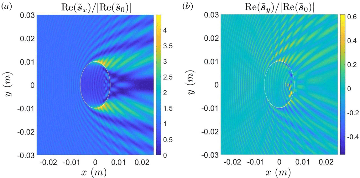
Starting with the filament radius, one way to study the effect of the magnitude of the cylinder radius on the scattering process, is by plotting figures of the time-independent Poynting vector as in (6.9), especially of the component which points to the forward direction. Figure 3 is referring to an incident wave of O-mode polarization and presents the
 $x$
- (a) and
 $y$
- (b) components of the Poynting vector, for a filament with radius equal to 2 mm, ambient density
 $10^{19}~\text{m}^{-3}$
, filament density
 $2.0\times 10^{19}~\text{m}^{-3}$
and magnetic field inclination zero. It must be noted that the figure 3 filament radius is of approximately the same size as the wavelength of the incident wave, since for the frequency of
 $170~\text{GHz}$
and the given ambient density, the wavelength is approximately 1.8 mm. The frequency of the RF wave has a major role in the scattering effects, which are different, when the wavelength is bigger, smaller or approximately the same size compared to the fluctuation. Figure 4 shows the
 $x$
-component (a) and
 $y$
-component (b) of the Poynting vector for a bigger filament with radius equal to 10 mm, also at the same (EC) frequency of
 $170~\text{GHz}$
. The
 $z$
-components of the Poynting vector are not presented, while they are zero (for an incident wave of O-mode polarization, there is by definition no
 $z$
-component of the Poynting vector; since the filament has no inclination with respect to the total magnetic field,
 $k_{z}$
is preserved and thus, the scattered wave has no
 $z$
-component, too).
Poynting vector
 $x$
- (a) and
 $y$
- (b) components, frequency
 $170~\text{GHz}$
, incident wave polarization O-mode, filament radius 2 mm, ambient density
 $10^{19}~\text{m}^{-3}$
and filament density
 $2.0\times 10^{19}~\text{m}^{-3}$
, magnetic field inclination
 $0^{\circ }$
, magnitude of magnetic induction
 $B=4.5T$
.

Poynting vector
 $x$
- (a) and
 $y$
- (b) components, frequency
 $170~\text{GHz}$
, incident wave polarization O-mode, filament radius 10 mm, ambient density
 $10^{19}~\text{m}^{-3}$
and filament density
 $2.0\times 10^{19}~\text{m}^{-3}$
, magnetic field inclination
 $0^{\circ }$
, magnitude of magnetic induction
 $B=4.5T$
.

In figure 5, one can see the Fourier spectrum (the left-hand side is the case with 2 mm radius and the right-hand side is the case with 10 mm radius). It is a polar diagram of the normalized spectral amplitude as a function of the horizontal and vertical projections of the Fourier mode number, normalized to the incident index of refraction. The peak (dot) in the centre of the diagram (point
 $(0,0)$
), corresponds to the spectrum of the incident wave. Without the scattering process which happens due to the filament, the Fourier spectrum has only one peak (dot) in the centre of the diagram (point
 $(0,0)$
). Because of the filament, the spectral amplitude is distributed as a cardioid due to the presence of the filament. Note that the maximum of the spectral density is in the forward direction. However, there is significant scattering at the filament’s sides.
Fourier spectrum: polar diagram of the horizontal and vertical projections of the Fourier mode number, normalized to the incident index of refraction. Frequency
 $170~\text{GHz}$
, incident wave polarization O-mode, ambient density
 $10^{19}~\text{m}^{-3}$
and filament density
 $2.0\times 10^{19}~\text{m}^{-3}$
, magnetic field inclination
 $0^{\circ }$
, magnitude of magnetic induction
 $B=4.5T$
. (a) The case with 2 mm radius and (b) the case with 10 mm radius.

Poynting vector
 $x$
- (a) and
 $y$
- (b) components, frequency
 $170~\text{GHz}$
, incident wave polarization O-mode, filament radius 10 mm, ambient density
 $10^{19}~\text{m}^{-3}$
and filament density
 $1.2\times 10^{19}~\text{m}^{-3}$
, magnetic field inclination
 $0^{\circ }$
, magnitude of magnetic induction
 $B=4.5T$
.

Fourier spectrum: polar diagram of the horizontal and vertical projections of the Fourier mode number, normalized to the incident index of refraction. Frequency
 $170~\text{GHz}$
, incident wave polarization O-mode, filament radius 10 mm, ambient density
 $10^{19}~\text{m}^{-3}$
and filament density
 $1.2\times 10^{19}~\text{m}^{-3}$
, magnetic field inclination
 $0^{\circ }$
, magnitude of magnetic induction
 $B=4.5T$
.

7.2 The way the filament density contrast affects RF scattering
Another interesting parameter for study is the density contrast between the cylindrical filament and the background environment. As mentioned in the Introduction (§ 1), the electron density of the filament can be very different compared to the ambient electron density, so that the absolute value of the relative density contrast between the filament and the ambient electron density can practically vary in a wide range of values: a typical experimental range of values is inside
 $(0.05,1)$
. In figure 6, the incident wave is of O-mode polarization. The
 $x$
- and
 $y$
- components of the Poynting vector of EC wave at frequency
 $170~\text{GHz}$
appear, for ambient density
 $10^{19}~\text{m}^{-3}$
and filament density
 $1.2\times 10^{19}~\text{m}^{-3}$
, radius equal to 10 mm. One can compare these results with the ones in figure 4, to see the differences between the relative density contrasts of
 $20\,\%$
and
 $100\,\%$
respectively. The
 $z$
-component of the Poynting vector is not presented as it is zero. The magnetic field inclination with respect to the cylinder axis, is also zero. In figure 7, the Fourier spectrum is presented and one can compare it with the one in figure 5 for the same cylinder radius, but different relative density contrast. It is evident that the spectral broadening due to the presence of the filament persists at higher azimuthal angles when the relative density contrast is higher.
7.3 RF scattering with magnetic field inclination with respect to the cylinder axis for O-mode incident waves
In figures 8 and 9, one can see the effect that the magnetic field inclination with respect to the cylinder axis has on the scattering process, by keeping the same magnitude of the magnetic induction
 $B=4.5T$
. These figures are referring to incident waves of O-mode polarization. For presentation purposes, the magnetic field is chosen to be at an angle of
 $50^{\circ }$
with respect to the cylinder axis (which is, of course, a big value), while the chosen frequency of
 $170~\text{GHz}$
is referring again to the EC waves case, the filament radius is equal to 10 mm, the ambient density is
 $10^{19}~\text{m}^{-3}$
and the filament density is
 $1.2\times 10^{19}~\text{m}^{-3}$
(so that the relative density contrast is
 $20\,\%$
). One can compare these results with the ones in figures 6 and 7. Note that the results are presented in the magnetic field’s frame of reference, which now is different from the cylindrical filament’s frame of reference and so, the cylinder appears to have an elliptical shape. It is obvious, that the scattering pattern is much more intense in the presence of inclination. This could be attributed to the excitation of additional modes in the interior of the filament, due to the fact that there is now a multitude of parallel to the magnetic field wave vectors not coinciding with the respective one for the incident wave (which is the case for the aligned filament).
Poynting vector
 $x$
- (a) and
 $y$
- (b) components, frequency
 $170~\text{GHz}$
, incident wave polarization O-mode, filament radius 10 mm, ambient density
 $10^{19}~\text{m}^{-3}$
and filament density
 $1.2\times 10^{19}~\text{m}^{-3}$
, magnetic field inclination
 $50^{\circ }$
, azimuth
 $0^{\circ }$
, magnitude of magnetic induction
 $B=4.5T$
.

Poynting vector
 $z$
-component (a), frequency
 $170~\text{GHz}$
, incident wave polarization O-mode, filament radius 10 mm, ambient density
 $10^{19}~\text{m}^{-3}$
and filament density
 $1.2\times 10^{19}~\text{m}^{-3}$
, magnetic field inclination
 $50^{\circ }$
, azimuth
 $0^{\circ }$
, magnitude of magnetic induction
 $B=4.5T$
. Fourier spectrum (b) polar diagram of the horizontal and vertical projections of the Fourier mode number, normalized to the incident index of refraction.

Figures 10 and 11, are also referring to incident waves of O-mode polarization and the parameters are the same as the ones in figures 8 and 9, with the difference that now, the ambient density is
 $10^{19}~\text{m}^{-3}$
the filament density is
 $2.0\times 10^{19}~\text{m}^{-3}$
(so that the relative density contrast is
 $100\,\%$
instead of
 $20\,\%$
). Note that the results are presented in a different colour map. However, it is evident that the scattering is much more intense in the case of higher relative density contrast. As a general remark, we may observe that in both cases of low and high contrast, a considerable fraction of the total power is channelled along the magnetic field lines, as expected.
7.4 RF scattering with magnetic field inclination with respect to the cylinder axis for X-mode incident waves
In figures 12–15, one can see the effect that the magnetic field inclination with respect to the cylinder axis has for incident waves of X-mode polarization.
Poynting vector
 $x$
- (a) and
 $y$
- (b) components, frequency
 $170~\text{GHz}$
, incident wave polarization O-mode, filament radius 10 mm, ambient density
 $10^{19}~\text{m}^{-3}$
and filament density
 $2.0\times 10^{19}~\text{m}^{-3}$
, magnetic field inclination
 $50^{\circ }$
, magnitude of magnetic induction
 $B=4.5T$
.

Poynting vector
 $z$
-component (a), frequency
 $170~\text{GHz}$
, incident wave polarization O-mode, filament radius 10 mm, ambient density
 $10^{19}~\text{m}^{-3}$
and filament density
 $2.0\times 10^{19}~\text{m}^{-3}$
, magnetic field inclination
 $50^{\circ }$
, azimuth
 $0^{\circ }$
, magnitude of magnetic induction
 $B=4.5T$
. Fourier spectrum (b): polar diagram of the horizontal and vertical projections of the Fourier mode number, normalized to the incident index of refraction.
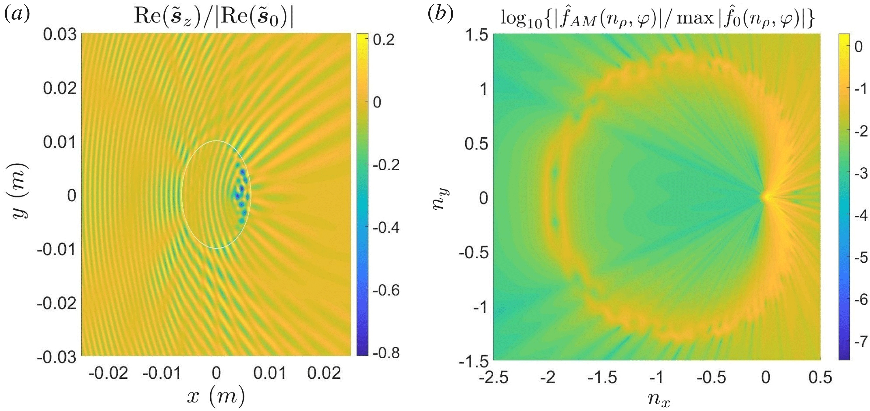
Figure 12 presents the
 $x$
- (a) and
 $y$
- (b) components of the Poynting vector, for a filament with radius equal to 10 mm, ambient density
 $10^{19}~\text{m}^{-3}$
, filament density
 $2.0\times 10^{19}~\text{m}^{-3}$
and magnetic field inclination zero. The
 $z$
-components of the Poynting vector are not presented as they are zero. In figure 13, the Fourier spectrum for the same case appears.
Poynting vector
 $x$
- (a) and
 $y$
- (b) components, frequency
 $170~\text{GHz}$
, incident wave polarization X-mode, filament radius 10 mm, ambient density
 $10^{19}~\text{m}^{-3}$
and filament density
 $2.0\times 10^{19}~\text{m}^{-3}$
, magnetic field inclination
 $0^{\circ }$
, magnitude of magnetic induction
 $B=4.5T$
.

Fourier spectrum: polar diagram of the horizontal and vertical projections of the Fourier mode number, normalized to the incident index of refraction. Frequency
 $170~\text{GHz}$
, incident wave polarization X-mode, filament radius 10 mm, ambient density
 $10^{19}~\text{m}^{-3}$
and filament density
 $2.0\times 10^{19}~\text{m}^{-3}$
, magnetic field inclination
 $0^{\circ }$
, magnitude of magnetic induction
 $B=4.5T$
.

In figures 14 and 15, the same case as for figures 12 and 13 is presented, with the difference that the magnetic field inclination with respect to the cylinder’s axis is
 $50^{\circ }$
instead of zero and as a result, the
 $z$
-component of the Poynting vector is not zero.
Poynting vector
 $x$
- (a) and
 $y$
- (b) components, frequency
 $170~\text{GHz}$
, incident wave polarization X-mode, filament radius 10 mm, ambient density
 $10^{19}~\text{m}^{-3}$
and filament density
 $2.0\times 10^{19}~\text{m}^{-3}$
, magnetic field inclination
 $50^{\circ }$
, magnitude of magnetic induction
 $B=4.5T$
.

Poynting vector
 $z$
-component (a), frequency
 $170~\text{GHz}$
, incident wave polarization X-mode, filament radius 10 mm, ambient density
 $10^{19}~\text{m}^{-3}$
and filament density
 $2.0\times 10^{19}~\text{m}^{-3}$
, magnetic field inclination
 $50^{\circ }$
, magnitude of magnetic induction
 $B=4.5T$
. Fourier spectrum (b) polar diagram of the horizontal and vertical projections of the Fourier mode number, normalized to the incident index of refraction.

8 Conclusions
The full-wave theoretical model presented in this paper, describes the scattering process of plane RF waves by a cylindrical filament embedded in an ambient magnetized plasma. In previous studies of RF scattering by cylindrical filaments, the axis of the cylinder was assumed to be parallel to the total magnetic field (see Ram Reference Ram and Hizanidis2016). The full-wave model presented has a main advantage compared to the geometric optics approximation: the electron density of the filament does not have to be close to the ambient electron density and thus, the full-wave approach has a more general validity in a much larger domain.
Maxwell’s equations have been used to derive the full-wave analytical model. In this study, due to the presence of a magnetic field component with general orientation relative to the cylindrical filament, the physics of the scattering phenomenon changes: while, in the case of a fully aligned with the magnetic field filament the component of the wave vector along the magnetic field
 $k_{\Vert }$
is preserved, in the case where a magnetic field component with different orientation is present, only the component of the wave vector along the cylinder axis
 $k_{z}$
is preserved. The latter is set by the incident wave. This mere fact introduces dependence of the polarizations on the azimuthal angle in the cylindrical filaments frame of reference. Thus, in the present analysis, in contrast with the aligned case, this dependence leads to integration over the azimuthal angle of all the modes involved and an additional summation over azimuthal numbers in the expression for the fields (6.1)–(6.4). In the aligned case, the respective exponential that contains the azimuthal angle collapses to a Kronecker delta function that isolates a particular azimuthal mode number from the aforementioned summation. Therefore, in the general model in hand and at the physics level, this leads to a scattered field for a spectrum of
 $k_{\Vert }$
values which depends on the angle
 $\unicode[STIX]{x1D719}_{0}$
of inclination between the axis of the filament and the direction of the total magnetic field. Thus, the presence of a broad
 $k_{\Vert }$
spectrum of waves alters the power deposition profile of the RF waves in the core of the plasma as compared to the aligned case.
The dispersion relation (3.14) can be satisfied by two independent plasma waves, one of which is the incident RF wave. Inside the filament, a set of wave modes are excited by the incident RF wave and each one of them is a linear combination of the two independent plasma waves. These wave modes propagate in all directions outside the filament and create wave modes that are linear combinations of the cold plasma waves. Therefore, there are scattered fields not only in the forward direction, but in the backward direction and sideways too, as it is clearly shown in the figures of § 7 where the numerical results are presented. A useful tool implemented in this work is the poloidal spectral diagram of the total power (the magnitude of the real part of the Poynting flux) emanating from the filament. In this diagram, the azimuthal angle refers to different azimuthal angles around the cylindrical filaments circumference and, thus, the respective spectral intensity amplitude around the cylinder provides a measure of the scattering process. The respective spectral figures of § 7 clearly show a broad and distributed spectral intensity around the filament shaped as a broad cardioid, instead of a single isolated dot which would present the Fourier spectrum of a plane monochromatic wave in the case where the filament is not present.
The filament radius can be of approximately the same, bigger than or smaller than the wavelength of the incident wave. To this end, filaments of different radii have been shown in § 7.1. As expected, the respective scattering effects are not the same. In fact, the scattering effects are stronger when the filament’s radius increases. At this point, it must be mentioned that for the EC frequency of
 $170~\text{GHz}$
and the ambient density of
 $10^{19}~\text{m}^{-3}$
which are both the same for all figures in § 7, the wavelength of the incident wave is approximately 1.8 mm. Concerning the relative density contrast between the filament and the ambient electron density, as referred to in the Introduction (§ 1), it can practically vary in a wide range of values and a typical experimental range of values is inside
 $(0.05,1)$
. The numerical simulations in § 7.2 have been made for a relative density contrast of
 $20\,\%$
and their results (figures 6 and 7) are compared to the ones in § 7.1 (figures 4 and 5) which are referring to a relative density contrast of
 $100\,\%$
. It is evident from these results, that the spatial variations in the power flow increase as the density contrast between the filament and the background increases. When the filament’s density gets larger relative to the background density, the scattering effects become stronger. When the density contrast between the filament and the background tends to zero, that is when the filament becomes indistinguishable from the ambient plasma, the scattering effects must tend to disappear.
In the figures of §§ 7.3 and 7.4, there are cases in which the total magnetic field is at a non-zero angle
 $\unicode[STIX]{x1D719}_{0}$
with respect to the axis of the cylindrical filament. It must be noted that the chosen values for
 $\unicode[STIX]{x1D719}_{0}$
for the simulations in the whole of § 7 are
 $\unicode[STIX]{x1D719}_{0}=0$
and
 $\unicode[STIX]{x1D719}_{0}=50^{\circ }$
. The value
 $\unicode[STIX]{x1D719}_{0}=50^{\circ }$
is intentionally large in order to demonstrate the differences between the general case of the present work and the previous cases for the fully aligned filament (see Ram Reference Ram and Hizanidis2016). In the figures of §§ 7.3 and 7.4, we observe that the scattering pattern is more intense in the presence of a poloidal magnetic field component, when the total magnetic field is at a non-zero angle
 $\unicode[STIX]{x1D719}_{0}$
with respect to the axis of the cylindrical filament. This could be attributed to the excitation of additional modes in the interior of the filament. This, in turn, is due to the fact that there is now a multitude of parallel to the magnetic field wave vectors not coinciding with the respective one for the incident wave (which is the case for the aligned filament). Moreover, comparing the figures of § 7.3 with the figures of § 7.4, it must be noticed that the scattering process has different characteristics when the incident wave is of O-mode polarization and when it is of X-mode polarization.
Acknowledgements
This work has been carried out within the framework of the EUROfusion Consortium and has received funding from the Euratom research and training programme 2014–2018 under grant agreement no. 633053 (except author A.K.R.). The views and opinions expressed herein do not necessarily reflect those of the European Commission. A.K.R. is supported by the US Department of Energy grant nos. DE-FG02-91ER-54109, DE-FG02-99ER-54525-NSTX and DE-FC02-01ER54648.
Appendix A. Transformation matrices
A.1 Transforming from the magnetic field coordinate system to the infinite length cylindrical filament coordinate system
In order to transform between the Cartesian coordinate systems of the filament and the magnetic field one has to rotate around the fixed axis
 $y$
with the help of the turning matrix
 $$\begin{eqnarray}\unicode[STIX]{x1D64D}_{y}(\unicode[STIX]{x1D719}_{0})\equiv \left(\begin{array}{@{}ccc@{}}\cos \unicode[STIX]{x1D719}_{0} & 0 & -\!\sin \unicode[STIX]{x1D719}_{0}\\ 0 & 1 & 0\\ \sin \unicode[STIX]{x1D719}_{0} & 0 & \cos \unicode[STIX]{x1D719}_{0}\end{array}\right)\end{eqnarray}$$
to obtain:
 $$\begin{eqnarray}\left(\begin{array}{@{}c@{}}\hat{\boldsymbol{x}}^{\prime }\\ \hat{\boldsymbol{y}}^{\prime }\\ \hat{\boldsymbol{z}}^{\prime }\end{array}\right)=\unicode[STIX]{x1D64D}_{y}(\unicode[STIX]{x1D719}_{0})\left(\begin{array}{@{}c@{}}\hat{\boldsymbol{x}}\\ \hat{\boldsymbol{y}}\\ \hat{\boldsymbol{z}}\end{array}\right),\quad \left(\begin{array}{@{}c@{}}\hat{\boldsymbol{x}}\\ \hat{\boldsymbol{y}}\\ \hat{\boldsymbol{z}}\end{array}\right)=\unicode[STIX]{x1D64D}_{y}(-\unicode[STIX]{x1D719}_{0})\left(\begin{array}{@{}c@{}}\hat{\boldsymbol{x}}^{\prime }\\ \hat{\boldsymbol{y}}^{\prime }\\ \hat{\boldsymbol{z}}^{\prime }\end{array}\right)\equiv \unicode[STIX]{x1D64D}_{y}^{-1}(\unicode[STIX]{x1D719}_{0})\left(\begin{array}{@{}c@{}}\hat{\boldsymbol{x}}^{\prime }\\ \hat{\boldsymbol{y}}^{\prime }\\ \hat{\boldsymbol{z}}^{\prime }\end{array}\right),\end{eqnarray}$$
where the primed unit vectors refer to the magnetic field line coordinate system with the same
 $y$
-axis. Similarly, for any vector
 $\boldsymbol{a}$
:
 $$\begin{eqnarray}\left(\begin{array}{@{}c@{}}a_{x}^{\prime }\\ a_{y}^{\prime }\\ a_{z}^{\prime }\end{array}\right)=\unicode[STIX]{x1D64D}_{y}(\unicode[STIX]{x1D719}_{0})\left(\begin{array}{@{}c@{}}a_{x}\\ a_{y}\\ a_{z}\end{array}\right),\quad \left(\begin{array}{@{}c@{}}a_{x}\\ a_{y}\\ a_{z}\end{array}\right)=\unicode[STIX]{x1D64D}_{y}(-\unicode[STIX]{x1D719}_{0})\left(\begin{array}{@{}c@{}}a_{x}^{\prime }\\ a_{y}^{\prime }\\ a_{z}^{\prime }\end{array}\right)\equiv \unicode[STIX]{x1D64D}_{y}^{-1}(\unicode[STIX]{x1D719}_{0})\left(\begin{array}{@{}c@{}}a_{x}^{\prime }\\ a_{y}^{\prime }\\ a_{z}^{\prime }\end{array}\right)\end{eqnarray}$$
and
 $$\begin{eqnarray}\displaystyle & \displaystyle \left(\begin{array}{@{}ccc@{}}a_{x}^{\prime } & a_{y}^{\prime } & a_{z}^{\prime }\end{array}\right)=\left(\begin{array}{@{}ccc@{}}a_{x} & a_{y} & a_{z}\end{array}\right)\unicode[STIX]{x1D64D}_{y}(-\unicode[STIX]{x1D719}_{0})\equiv \left(\begin{array}{@{}ccc@{}}a_{x} & a_{y} & a_{z}\end{array}\right)\unicode[STIX]{x1D64D}_{y}^{-1}(\unicode[STIX]{x1D719}_{0}) & \displaystyle\end{eqnarray}$$
 $$\begin{eqnarray}\displaystyle & \displaystyle \left(\begin{array}{@{}ccc@{}}a_{x} & a_{y} & a_{z}\end{array}\right)=\left(\begin{array}{@{}ccc@{}}a_{x}^{\prime } & a_{y}^{\prime } & a_{z}^{\prime }\end{array}\right)\unicode[STIX]{x1D64D}_{y}(\unicode[STIX]{x1D719}_{0}). & \displaystyle\end{eqnarray}$$
A.2 Transforming from Cartesian to cylindrical coordinates and vice versa
While in the cylinder (filament) based frame of reference, one can transform from a Cartesian coordinate system to cylindrical coordinates in the same frame. Thus, by using the transformation matrix
 $$\begin{eqnarray}\unicode[STIX]{x1D64D}_{c}(\unicode[STIX]{x1D711}_{k})=\left(\begin{array}{@{}ccc@{}}\cos \unicode[STIX]{x1D711}_{k} & -\!\sin \unicode[STIX]{x1D711}_{k} & 0\\ \sin \unicode[STIX]{x1D711}_{k} & \cos \unicode[STIX]{x1D711}_{k} & 0\\ 0 & 0 & 1\end{array}\right)\end{eqnarray}$$
one obtains:
 $$\begin{eqnarray}\left(\begin{array}{@{}c@{}}\hat{\boldsymbol{x}}\\ \hat{\boldsymbol{y}}\\ \hat{\boldsymbol{z}}\end{array}\right)=\unicode[STIX]{x1D64D}_{c}(\unicode[STIX]{x1D711}_{k})\left(\begin{array}{@{}c@{}}\hat{\boldsymbol{r}}\\ \hat{\unicode[STIX]{x1D753}}\\ \hat{\boldsymbol{z}}\end{array}\right),\quad \left(\begin{array}{@{}c@{}}\hat{\boldsymbol{r}}\\ \hat{\unicode[STIX]{x1D753}}\\ \hat{\boldsymbol{z}}\end{array}\right)=\unicode[STIX]{x1D64D}_{c}(-\unicode[STIX]{x1D711}_{k})\left(\begin{array}{@{}c@{}}\hat{\boldsymbol{x}}\\ \hat{\boldsymbol{y}}\\ \hat{\boldsymbol{z}}\end{array}\right)\equiv \unicode[STIX]{x1D64D}_{c}^{-1}(\unicode[STIX]{x1D711}_{k})\left(\begin{array}{@{}c@{}}\hat{\boldsymbol{x}}\\ \hat{\boldsymbol{y}}\\ \hat{\boldsymbol{z}}\end{array}\right).\end{eqnarray}$$
Here,
 $\unicode[STIX]{x1D711}_{k}$
refers to the azimuthal angle in the filament-based coordinate system. Similarly, for any vector
 $\boldsymbol{a}$
:
 $$\begin{eqnarray}\left(\begin{array}{@{}c@{}}a_{x}\\ a_{y}\\ a_{z}\end{array}\right)=\unicode[STIX]{x1D64D}_{c}(\unicode[STIX]{x1D711}_{k})\left(\begin{array}{@{}c@{}}a_{r}\\ a_{\unicode[STIX]{x1D711}}\\ a_{z}\end{array}\right),\quad \left(\begin{array}{@{}c@{}}a_{r}\\ a_{\unicode[STIX]{x1D711}}\\ a_{z}\end{array}\right)=\unicode[STIX]{x1D64D}_{c}(-\unicode[STIX]{x1D711}_{k})\left(\begin{array}{@{}c@{}}a_{x}\\ a_{y}\\ a_{z}\end{array}\right)\equiv \unicode[STIX]{x1D64D}_{c}^{-1}(\unicode[STIX]{x1D711}_{k})\left(\begin{array}{@{}c@{}}a_{x}\\ a_{y}\\ a_{z}\end{array}\right)\end{eqnarray}$$
and
 $$\begin{eqnarray}\displaystyle & \displaystyle \left(\begin{array}{@{}ccc@{}}a_{x} & a_{y} & a_{z}\end{array}\right)=\left(\begin{array}{@{}ccc@{}}a_{r} & a_{\unicode[STIX]{x1D711}} & a_{z}\end{array}\right)\unicode[STIX]{x1D64D}_{c}(-\unicode[STIX]{x1D711}_{k})\equiv \left(\begin{array}{@{}ccc@{}}a_{r} & a_{\unicode[STIX]{x1D711}} & a_{z}\end{array}\right)\unicode[STIX]{x1D64D}_{c}^{-1}(\unicode[STIX]{x1D711}_{k}) & \displaystyle\end{eqnarray}$$
 $$\begin{eqnarray}\displaystyle & \displaystyle \left(\begin{array}{@{}ccc@{}}a_{r} & a_{\unicode[STIX]{x1D711}} & a_{z}\end{array}\right)=\left(\begin{array}{@{}ccc@{}}a_{x} & a_{y} & a_{z}\end{array}\right)\unicode[STIX]{x1D64D}_{c}(\unicode[STIX]{x1D711}_{k}). & \displaystyle\end{eqnarray}$$
Appendix B. Cylindrical vector functions
The cylindrical vector functions (see Stratton Reference Stratton1941) in cylindrical coordinates are as follows:
 $$\begin{eqnarray}\displaystyle & \displaystyle \boldsymbol{m}_{n}(n_{\unicode[STIX]{x1D70C}}\unicode[STIX]{x1D70C},n_{z}\unicode[STIX]{x1D701},\unicode[STIX]{x1D711})\equiv \left[\text{i}n\frac{Z_{n}(n_{\unicode[STIX]{x1D70C}}\unicode[STIX]{x1D70C})}{\unicode[STIX]{x1D70C}}\hat{\boldsymbol{r}}-\frac{\text{d}Z_{n}(n_{\unicode[STIX]{x1D70C}}\unicode[STIX]{x1D70C})}{\text{d}\unicode[STIX]{x1D70C}}\hat{\unicode[STIX]{x1D753}}\right]\exp [\text{i}(n_{z}\unicode[STIX]{x1D701}+n\unicode[STIX]{x1D711})] & \displaystyle\end{eqnarray}$$
 $$\begin{eqnarray}\displaystyle & \displaystyle \boldsymbol{n}_{n}(n_{\unicode[STIX]{x1D70C}}\unicode[STIX]{x1D70C},n_{z}\unicode[STIX]{x1D701},\unicode[STIX]{x1D711})\equiv \left\{\frac{n_{z}}{n}\left[\text{i}\frac{\text{d}Z_{n}(n_{\unicode[STIX]{x1D70C}}\unicode[STIX]{x1D70C})}{\text{d}\unicode[STIX]{x1D70C}}\hat{\boldsymbol{r}}-n\frac{Z_{n}(n_{\unicode[STIX]{x1D70C}}\unicode[STIX]{x1D70C})}{\unicode[STIX]{x1D70C}}\hat{\unicode[STIX]{x1D753}}\right]+\frac{n_{\unicode[STIX]{x1D70C}}^{2}}{n}Z_{n}(n_{\unicode[STIX]{x1D70C}}\unicode[STIX]{x1D70C})\hat{\boldsymbol{z}}\right\}\exp [\text{i}(n_{z}\unicode[STIX]{x1D701}+n\unicode[STIX]{x1D711})] & \displaystyle \nonumber\\ \displaystyle & & \displaystyle\end{eqnarray}$$
and
 $$\begin{eqnarray}\boldsymbol{l}_{n}(n_{\unicode[STIX]{x1D70C}}\unicode[STIX]{x1D70C},n_{z}\unicode[STIX]{x1D701},\unicode[STIX]{x1D711})\equiv \left[\frac{\text{d}Z_{n}(n_{\unicode[STIX]{x1D70C}}\unicode[STIX]{x1D70C})}{\text{d}\unicode[STIX]{x1D70C}}\hat{\boldsymbol{r}}+\text{i}n\frac{Z_{n}(n_{\unicode[STIX]{x1D70C}}\unicode[STIX]{x1D70C})}{\unicode[STIX]{x1D70C}}\hat{\unicode[STIX]{x1D753}}+\text{i}n_{z}Z_{n}(n_{\unicode[STIX]{x1D70C}}\unicode[STIX]{x1D70C})\hat{\boldsymbol{z}}\right]\exp [\text{i}(n_{z}\unicode[STIX]{x1D701}+n\unicode[STIX]{x1D711})].\end{eqnarray}$$
Note that these vector functions are expressed in terms of the position in space (in cylindrical coordinates), while the wave enters only via its axial and radial refractive indices in the cylinder frame of reference. For the incident wave the Bessel functions involved are
 $\text{J}_{n}$
. The vector functions obey the following relations:
 $$\begin{eqnarray}\unicode[STIX]{x1D735}\boldsymbol{\cdot }\boldsymbol{m}_{n}=0,\quad \unicode[STIX]{x1D735}\boldsymbol{\cdot }\boldsymbol{n}_{n}=0,\quad \unicode[STIX]{x1D735}\boldsymbol{\cdot }\boldsymbol{l}_{n}=-n^{2}Z_{n}\exp [\text{i}(n_{z}\unicode[STIX]{x1D701}+n\unicode[STIX]{x1D711})]\end{eqnarray}$$
as well as:
 $$\begin{eqnarray}\unicode[STIX]{x1D735}\times \boldsymbol{l}_{n}=0,\quad \unicode[STIX]{x1D735}\times \boldsymbol{m}_{n}=n\boldsymbol{n}_{n},\quad \unicode[STIX]{x1D735}\times \boldsymbol{n}_{n}=n\boldsymbol{m}_{n}.\end{eqnarray}$$
Appendix C. The dispersion tensor
The dispersion tensor elements in cylindrical coordinates, in the filament’s frame of reference, are:
 $$\begin{eqnarray}\displaystyle & \displaystyle (\unicode[STIX]{x1D60B}_{fila}^{cyl})_{11}=c_{k}^{2}(K_{\bot }c_{0}^{2}+K_{\Vert }s_{0}^{2})+K_{\bot }s_{k}^{2}-n_{\unicode[STIX]{x1D711}}^{2}-n_{z}^{2} & \displaystyle\end{eqnarray}$$
 $$\begin{eqnarray}\displaystyle & \displaystyle (\unicode[STIX]{x1D60B}_{fila}^{cyl})_{12}=-s_{k}c_{k}(K_{\bot }c_{0}^{2}+K_{\Vert }s_{0}^{2})+K_{\bot }s_{k}c_{k}-\text{i}K_{\times }c_{0}+n_{\unicode[STIX]{x1D70C}}n_{\unicode[STIX]{x1D711}} & \displaystyle\end{eqnarray}$$
 $$\begin{eqnarray}\displaystyle & \displaystyle (\unicode[STIX]{x1D60B}_{fila}^{cyl})_{13}=c_{k}c_{0}s_{0}(K_{\Vert }-K_{\bot })-\text{i}K_{\times }s_{0}s_{k}+n_{\unicode[STIX]{x1D70C}}n_{z} & \displaystyle\end{eqnarray}$$
 $$\begin{eqnarray}\displaystyle & \displaystyle (\unicode[STIX]{x1D60B}_{fila}^{cyl})_{21}=-s_{k}c_{k}(K_{\bot }c_{0}^{2}+K_{\Vert }s_{0}^{2})+K_{\bot }s_{k}c_{k}+\text{i}K_{\times }c_{0}+n_{\unicode[STIX]{x1D70C}}n_{\unicode[STIX]{x1D711}} & \displaystyle\end{eqnarray}$$
 $$\begin{eqnarray}\displaystyle & \displaystyle (\unicode[STIX]{x1D60B}_{fila}^{cyl})_{22}=s_{k}^{2}(K_{\bot }c_{0}^{2}+K_{\Vert }s_{0}^{2})+K_{\bot }c_{k}^{2}-n_{\unicode[STIX]{x1D70C}}^{2}-n_{z}^{2} & \displaystyle\end{eqnarray}$$
 $$\begin{eqnarray}\displaystyle & \displaystyle (\unicode[STIX]{x1D60B}_{fila}^{cyl})_{23}=-s_{k}c_{0}s_{0}(K_{\Vert }-K_{\bot })-\text{i}K_{\times }s_{0}c_{k}+n_{\unicode[STIX]{x1D711}}n_{z} & \displaystyle\end{eqnarray}$$
 $$\begin{eqnarray}\displaystyle & \displaystyle (\unicode[STIX]{x1D60B}_{fila}^{cyl})_{31}=c_{k}c_{0}s_{0}(K_{\Vert }-K_{\bot })+\text{i}K_{\times }s_{0}s_{k}+n_{\unicode[STIX]{x1D70C}}n_{z} & \displaystyle\end{eqnarray}$$
 $$\begin{eqnarray}\displaystyle & \displaystyle (\unicode[STIX]{x1D60B}_{fila}^{cyl})_{32}=-s_{k}c_{0}s_{0}(K_{\Vert }-K_{\bot })+\text{i}K_{\times }s_{0}c_{k}+n_{\unicode[STIX]{x1D711}}n_{z} & \displaystyle\end{eqnarray}$$
 $$\begin{eqnarray}\displaystyle & \displaystyle (\unicode[STIX]{x1D60B}_{fila}^{cyl})_{33}=(K_{\bot }s_{0}^{2}+K_{\Vert }c_{0}^{2})-n_{\unicode[STIX]{x1D70C}}^{2}-n_{\unicode[STIX]{x1D711}}^{2}. & \displaystyle\end{eqnarray}$$
Appendix D. Wave polarizations
By solving the system of (3.14),
 $r_{O\unicode[STIX]{x1D70C}}^{P}$
,
 $r_{O\unicode[STIX]{x1D711}}^{P}$
,
 $r_{Oz}^{P}$
,
 $r_{X\unicode[STIX]{x1D70C}}^{P}$
,
 $r_{X\unicode[STIX]{x1D711}}^{P}$
and
 $r_{Xz}^{P}$
are:
 $$\begin{eqnarray}\left.\begin{array}{@{}rcl@{}}r_{O\unicode[STIX]{x1D70C}}^{P}\,\, & =\,\, & {\displaystyle \frac{1}{d_{O}}}(K_{\bot }-K_{\Vert })[n_{\unicode[STIX]{x1D70C}}n_{0z}s_{0}s^{2}+(K_{\bot }-n^{2})c_{0}c]s_{0}-(K_{\bot }-n^{2})n_{\unicode[STIX]{x1D70C}}n_{0z}-K_{\times }^{2}c_{0}s_{0}c\\ \,\, & \,\, & +\,\text{i}K_{\times }(K_{\Vert }-n^{2})ss_{0}\\ r_{O\unicode[STIX]{x1D711}}^{P}\,\, & =\,\, & {\displaystyle \frac{1}{d_{O}}}\left\{K_{\times }^{2}c_{0}+[n_{\unicode[STIX]{x1D70C}}n_{0z}cs_{0}-(K_{\bot }-n_{0z}^{2})c_{0}](K_{\bot }-K_{\Vert })\right\}ss_{0}\\ \,\, & \,\, & +\,\text{i}K_{\times }[(K_{\Vert }-n_{0z}^{2})s_{0}c+n_{\unicode[STIX]{x1D70C}}n_{0z}c_{0}]\\ r_{Oz}^{P}\,\, & =\,\, & 1,\\ \text{where}\,\, & \,\, & \\ d_{O}\,\, & \equiv \,\, & (n^{2}-n_{\unicode[STIX]{x1D70C}}^{2}s^{2})(K_{\bot }-K_{\Vert })s_{0}^{2}+(K_{\bot }c_{0}^{2}+K_{\Vert }s_{0}^{2}-n^{2})K_{\bot }-(K_{\bot }-n^{2})n_{0z}^{2}-K_{\times }^{2}c_{0}^{2}\end{array}\right\}\end{eqnarray}$$
and
 $$\begin{eqnarray}\left.\begin{array}{@{}rcl@{}}r_{X\unicode[STIX]{x1D70C}}^{P}\,\, & =\,\, & 1\\ r_{X\unicode[STIX]{x1D711}}^{P}\,\, & =\,\, & {\displaystyle \frac{1}{d_{X}}}(K_{\bot }-K_{\Vert })n_{\unicode[STIX]{x1D70C}}n_{0z}s_{0}c_{0}s+[K_{\times }^{2}-(K_{\bot }-K_{\Vert })(K_{\bot }-n_{\unicode[STIX]{x1D70C}}^{2})]css_{0}^{2}\\ \,\, & \,\, & -\,\text{i}K_{\times }[(K_{\Vert }-n_{\unicode[STIX]{x1D70C}}^{2})c_{0}+n_{\unicode[STIX]{x1D70C}}n_{0z}s_{0}c]\\ r_{Xz}^{P}\,\, & =\,\, & {\displaystyle \frac{1}{d_{X}}}(K_{\bot }-K_{\Vert })[n_{\unicode[STIX]{x1D70C}}n_{0z}s_{0}s^{2}+(K_{\bot }-n^{2})c_{0}c]s_{0}-(K_{\bot }-n^{2})n_{\unicode[STIX]{x1D70C}}n_{0z}-K_{\times }^{2}s_{0}c_{0}c\\ \,\, & \,\, & -\,\text{i}K_{\times }(K_{\Vert }-n^{2})s_{0}s,\\ \text{where}\,\, & \,\, & \\ d_{X}\,\, & \equiv \,\, & -(K_{\bot }-n^{2})n_{\unicode[STIX]{x1D70C}}^{2}-n^{2}K_{\Vert }c_{0}^{2}+(s^{2}s_{0}^{2}+c_{0}^{2})K_{\bot }K_{\Vert }\\ \,\, & \,\, & +\,\left\{[K_{\bot }(K_{\bot }-n_{\unicode[STIX]{x1D70C}}^{2})-K_{\times }^{2}]c^{2}-K_{\Vert }n_{\unicode[STIX]{x1D70C}}^{2}s^{2}-K_{\bot }n_{0z}^{2}\right\}s_{0}^{2}.\end{array}\right\}\end{eqnarray}$$
Appendix E. The linear system that boundary conditions imply
The linear system that the boundary conditions imply, is described by the (5.5) with the coefficients
 $a_{j,mn}^{O/X,FI/SC}$
and
 $a_{j,m}^{0}$
being calculated as follows:
 $$\begin{eqnarray}\displaystyle & \displaystyle a_{1,mn}^{M,FI}=\int _{0}^{2\unicode[STIX]{x03C0}}\frac{\text{d}\unicode[STIX]{x1D711}_{k}}{2\unicode[STIX]{x03C0}}\text{e}^{\text{i}(n-m)\unicode[STIX]{x1D711}_{k}}\left(\text{i}\hat{E}_{k\unicode[STIX]{x1D711}_{k}}^{M}J_{m}^{^{\prime }M}-\hat{E}_{k\unicode[STIX]{x1D70C}}^{M}\frac{mJ_{m}^{M}}{n_{k\unicode[STIX]{x1D70C}}^{M}a}\right) & \displaystyle\end{eqnarray}$$
 $$\begin{eqnarray}\displaystyle & \displaystyle a_{1,mn}^{M,SC}=\int _{0}^{2\unicode[STIX]{x03C0}}\frac{\text{d}\unicode[STIX]{x1D711}_{k}}{2\unicode[STIX]{x03C0}}\text{e}^{\text{i}(n-m)\unicode[STIX]{x1D711}_{k}}\left(\text{i}\hat{E}_{k\unicode[STIX]{x1D711}_{k}}^{M}H_{m}^{^{\prime }(1)M}-\hat{E}_{k\unicode[STIX]{x1D70C}}^{M}\frac{mH_{m}^{(1)M}}{n_{k\unicode[STIX]{x1D70C}}^{M}a}\right) & \displaystyle\end{eqnarray}$$
 $$\begin{eqnarray}\displaystyle & \displaystyle a_{1,m}^{0}=\text{e}^{-\text{i}m\unicode[STIX]{x1D711}_{0}}\left(\text{i}\hat{E}_{0\unicode[STIX]{x1D711}_{0}}J_{m}^{^{\prime }0}-\hat{E}_{0\unicode[STIX]{x1D70C}}\frac{mJ_{m}^{0}}{n_{0\unicode[STIX]{x1D70C}}a}\right) & \displaystyle\end{eqnarray}$$
 $$\begin{eqnarray}\displaystyle & \displaystyle a_{2,mn}^{M,FI}=\int _{0}^{2\unicode[STIX]{x03C0}}\frac{\text{d}\unicode[STIX]{x1D711}_{k}}{2\unicode[STIX]{x03C0}}\text{e}^{\text{i}(n-m)\unicode[STIX]{x1D711}_{k}}(\hat{E}_{kz}^{M}J_{m}^{M}) & \displaystyle\end{eqnarray}$$
 $$\begin{eqnarray}\displaystyle & \displaystyle a_{2,mn}^{M,SC}=\int _{0}^{2\unicode[STIX]{x03C0}}\frac{\text{d}\unicode[STIX]{x1D711}_{k}}{2\unicode[STIX]{x03C0}}\text{e}^{\text{i}(n-m)\unicode[STIX]{x1D711}_{k}}(\hat{E}_{kz}^{M}H_{m}^{(1)M}) & \displaystyle\end{eqnarray}$$
 $$\begin{eqnarray}\displaystyle & \displaystyle a_{2,m}^{0}=\text{e}^{-\text{i}m\unicode[STIX]{x1D711}_{0}}(\hat{E}_{0z}J_{m}^{0}) & \displaystyle\end{eqnarray}$$
 $$\begin{eqnarray}\displaystyle & \displaystyle a_{3,mn}^{M,FI}=\int _{0}^{2\unicode[STIX]{x03C0}}\frac{\text{d}\unicode[STIX]{x1D711}_{k}}{2\unicode[STIX]{x03C0}}\text{e}^{\text{i}(n-m)\unicode[STIX]{x1D711}_{k}}\left[\text{i}(\hat{E}_{kz}^{M}n_{k\unicode[STIX]{x1D70C}}^{M}-\hat{E}_{k\unicode[STIX]{x1D70C}}^{M}n_{0z})J_{m}^{^{\prime }M}-\hat{E}_{k\unicode[STIX]{x1D711}_{k}}^{M}n_{0z}\frac{mJ_{m}^{M}}{n_{k\unicode[STIX]{x1D70C}}^{M}a}\right] & \displaystyle\end{eqnarray}$$
 $$\begin{eqnarray}\displaystyle & \displaystyle a_{3,mn}^{M,SC}=\int _{0}^{2\unicode[STIX]{x03C0}}\frac{\text{d}\unicode[STIX]{x1D711}_{k}}{2\unicode[STIX]{x03C0}}\text{e}^{\text{i}(n-m)\unicode[STIX]{x1D711}_{k}}\left[\text{i}(\hat{E}_{kz}^{M}n_{k\unicode[STIX]{x1D70C}}^{M}-\hat{E}_{k\unicode[STIX]{x1D70C}}^{M}n_{0z})H_{m}^{^{\prime }(1)M}-\hat{E}_{k\unicode[STIX]{x1D711}_{k}}^{M}n_{0z}\frac{mH_{m}^{(1)M}}{n_{k\unicode[STIX]{x1D70C}}^{M}a}\right] & \displaystyle\end{eqnarray}$$
 $$\begin{eqnarray}\displaystyle & \displaystyle a_{3,m}^{0}=\text{e}^{-\text{i}m\unicode[STIX]{x1D711}_{0}}\left[\text{i}(\hat{E}_{0z}n_{0\unicode[STIX]{x1D70C}}-\hat{E}_{0\unicode[STIX]{x1D70C}}n_{0z})J_{m}^{^{\prime }0}-\hat{E}_{0\unicode[STIX]{x1D711}_{0}}^{M}n_{0z}\frac{mJ_{m}^{0}}{n_{0\unicode[STIX]{x1D70C}}a}\right] & \displaystyle\end{eqnarray}$$
 $$\begin{eqnarray}\displaystyle & \displaystyle a_{4,mn}^{M,FI}=\int _{0}^{2\unicode[STIX]{x03C0}}\frac{\text{d}\unicode[STIX]{x1D711}_{k}}{2\unicode[STIX]{x03C0}}\text{e}^{\text{i}(n-m)\unicode[STIX]{x1D711}_{k}}(\hat{E}_{k\unicode[STIX]{x1D711}_{k}}^{M}n_{k\unicode[STIX]{x1D70C}}^{M}J_{m}^{M}) & \displaystyle\end{eqnarray}$$
 $$\begin{eqnarray}\displaystyle & \displaystyle a_{4,mn}^{M,SC}=\int _{0}^{2\unicode[STIX]{x03C0}}\frac{\text{d}\unicode[STIX]{x1D711}_{k}}{2\unicode[STIX]{x03C0}}\text{e}^{\text{i}(n-m)\unicode[STIX]{x1D711}_{k}}(\hat{E}_{k\unicode[STIX]{x1D711}_{k}}^{M}n_{k\unicode[STIX]{x1D70C}}^{M}H_{m}^{(1)M}) & \displaystyle\end{eqnarray}$$
 $$\begin{eqnarray}\displaystyle & \displaystyle a_{4,m}^{0}=\text{e}^{-\text{i}m\unicode[STIX]{x1D711}_{0}}(\hat{E}_{0\unicode[STIX]{x1D711}_{0}}n_{0\unicode[STIX]{x1D70C}}J_{m}^{0}). & \displaystyle\end{eqnarray}$$
Appendix F. Expressions of electric and magnetic field in terms of the cylindrical vector functions
Equation (3.2) takes the general form
 $$\begin{eqnarray}\boldsymbol{E}(\unicode[STIX]{x1D746})=\mathop{\sum }_{M=1}^{4}\int _{0}^{2\unicode[STIX]{x03C0}}\,\text{d}\unicode[STIX]{x1D711}_{k}\int _{-\infty }^{\infty }\text{d}n_{kz}\boldsymbol{E}_{k}[n_{k\unicode[STIX]{x1D70C}}(n_{kz},\unicode[STIX]{x1D711}_{k}),n_{kz},\unicode[STIX]{x1D711}_{k}]\exp (\text{i}\boldsymbol{n}\boldsymbol{\cdot }\unicode[STIX]{x1D746}),\end{eqnarray}$$
with the letter ‘
 $M$
’ denoting which one of the four solutions is referred to. Equivalently, by using the solutions of (F 1):
 $$\begin{eqnarray}\displaystyle \boldsymbol{E}(\unicode[STIX]{x1D70C},\unicode[STIX]{x1D711},\unicode[STIX]{x1D701}) & = & \displaystyle \mathop{\sum }_{M=1}^{4}\int _{0}^{2\unicode[STIX]{x03C0}}\,\text{d}\unicode[STIX]{x1D711}_{k}\int _{-\infty }^{\infty }\text{d}n_{kz}\boldsymbol{E}_{k}^{M}[n_{k\unicode[STIX]{x1D70C}}^{M}(n_{kz},\unicode[STIX]{x1D711}_{k}),n_{kz},\unicode[STIX]{x1D711}_{k}]\nonumber\\ \displaystyle & & \displaystyle \times \,\exp \left\{\text{i}\left[\unicode[STIX]{x1D70C}n_{k\unicode[STIX]{x1D70C}}^{M}\cos (\unicode[STIX]{x1D711}-\unicode[STIX]{x1D711}_{k})+n_{kz}\unicode[STIX]{x1D701}\right]\!\right\}.\end{eqnarray}$$
By normalizing the expression (F 2) for the electric field, one obtains:
 $$\begin{eqnarray}\displaystyle \boldsymbol{e}(\unicode[STIX]{x1D746}) & = & \displaystyle \frac{\boldsymbol{E}(\unicode[STIX]{x1D746})}{{\mathcal{E}}_{0}}=\int _{0}^{2\unicode[STIX]{x03C0}}\,\text{d}\unicode[STIX]{x1D711}_{k}\int _{-\infty }^{\infty }\text{d}n_{kz}\nonumber\\ \displaystyle & & \displaystyle \times \mathop{\sum }_{M=O,X}\{\boldsymbol{e}_{k}^{M}[n_{k\unicode[STIX]{x1D70C}}^{M}(\unicode[STIX]{x1D711}_{k},n_{kz}),\unicode[STIX]{x1D711}_{k},n_{kz}]+\boldsymbol{e}_{k}^{M}[-n_{k\unicode[STIX]{x1D70C}}^{M}(\unicode[STIX]{x1D711}_{k},n_{kz}),\unicode[STIX]{x1D711}_{k},n_{kz}]\}\text{e}^{\text{i}n_{k\unicode[STIX]{x1D70C}}^{M}\unicode[STIX]{x1D70C}\cos (\unicode[STIX]{x1D711}-\unicode[STIX]{x1D711}_{k})+\text{i}n_{kz}\unicode[STIX]{x1D701}},\nonumber\\ \displaystyle & & \displaystyle\end{eqnarray}$$
where
 ${\mathcal{E}}_{0}$
is the amplitude of the electric field intensity and also each one of the eigenmodes under the integral sign is spatially constant. For the incident field on the other hand,
 $$\begin{eqnarray}\boldsymbol{e}_{0}(\unicode[STIX]{x1D746})=\frac{\boldsymbol{E}_{0}(\unicode[STIX]{x1D746})}{{\mathcal{E}}_{0}}=\boldsymbol{e}_{0}(\unicode[STIX]{x1D711}_{0},n_{0z})\text{e}^{\text{i}n_{0\unicode[STIX]{x1D70C}}\unicode[STIX]{x1D70C}\cos (\unicode[STIX]{x1D711}-\unicode[STIX]{x1D711}_{0})+\text{i}n_{0z}\unicode[STIX]{x1D701}}.\end{eqnarray}$$
In terms of the cylindrical vector functions and the exponential dyadic, finally we have:
 $$\begin{eqnarray}\displaystyle \boldsymbol{e}(\unicode[STIX]{x1D746}) & = & \displaystyle \mathop{\sum }_{m=-\infty }^{m=\infty }\text{i}^{m}\int _{0}^{2\unicode[STIX]{x03C0}}\,\text{d}\unicode[STIX]{x1D711}_{k}\int _{-\infty }^{\infty }\text{d}n_{kz}\mathop{\sum }_{M=O,X}\mathop{\sum }_{n=-\infty }^{n=\infty }\unicode[STIX]{x1D700}_{n}^{M} (n_{kz}\text{e}^{\text{i}(n-m)\unicode[STIX]{x1D711}_{k}}\nonumber\\ \displaystyle & & \displaystyle \times \,\left\{\text{i}\frac{\hat{E}_{k\unicode[STIX]{x1D711}_{k}}^{M}}{n_{k\unicode[STIX]{x1D70C}}^{M}}\boldsymbol{m}_{m}(\unicode[STIX]{x1D70C}n_{k\unicode[STIX]{x1D70C}}^{M},\unicode[STIX]{x1D711},\unicode[STIX]{x1D701}n_{kz})+\frac{\hat{E}_{kz}^{M}n_{k\unicode[STIX]{x1D70C}}^{M}-\hat{E}_{k\unicode[STIX]{x1D70C}}^{M}n_{kz}}{n_{k\unicode[STIX]{x1D70C}}^{M}n_{k}^{M}}\boldsymbol{n}_{m}(\unicode[STIX]{x1D70C}n_{k\unicode[STIX]{x1D70C}}^{M},\unicode[STIX]{x1D711},\unicode[STIX]{x1D701}n_{kz})\right.\nonumber\\ \displaystyle & & \displaystyle \left.-\,\text{i}\frac{\hat{E}_{k\unicode[STIX]{x1D70C}}^{M}n_{k\unicode[STIX]{x1D70C}}^{M}+\hat{E}_{kz}^{M}n_{kz}}{(n_{k}^{M})^{2}}\boldsymbol{l}_{m}(\unicode[STIX]{x1D70C}n_{k\unicode[STIX]{x1D70C}}^{M},\unicode[STIX]{x1D711},\unicode[STIX]{x1D701}n_{kz})\right\}.\end{eqnarray}$$
For the incident wave, one obtains,
 $$\begin{eqnarray}\displaystyle \boldsymbol{e}_{0}(\unicode[STIX]{x1D746}) & = & \displaystyle \mathop{\sum }_{m=-\infty }^{m=\infty }\text{i}^{m}\text{e}^{-\text{i}m\unicode[STIX]{x1D711}_{0}}\left\{\text{i}\frac{\hat{E}_{0\unicode[STIX]{x1D711}_{0}}}{n_{0\unicode[STIX]{x1D70C}}}\boldsymbol{m}_{m}(\unicode[STIX]{x1D70C}n_{0\unicode[STIX]{x1D70C}},\unicode[STIX]{x1D711},\unicode[STIX]{x1D701}n_{0z})+\frac{\hat{E}_{0z}n_{0\unicode[STIX]{x1D70C}}-\hat{E}_{0\unicode[STIX]{x1D70C}}n_{0z}}{n_{0\unicode[STIX]{x1D70C}}n_{0}}\boldsymbol{n}_{m}(\unicode[STIX]{x1D70C}n_{0\unicode[STIX]{x1D70C}},\unicode[STIX]{x1D711},\unicode[STIX]{x1D701}n_{0z})\right.\nonumber\\ \displaystyle & & \displaystyle \left.-\,\text{i}\frac{\hat{E}_{0\unicode[STIX]{x1D70C}}n_{0\unicode[STIX]{x1D70C}}+\hat{E}_{0z}n_{0z}}{n_{0}^{2}}\boldsymbol{l}_{m}(\unicode[STIX]{x1D70C}n_{0\unicode[STIX]{x1D70C}},\unicode[STIX]{x1D711},\unicode[STIX]{x1D701}n_{0z})\right\}.\end{eqnarray}$$
Notice that for the aligned cylinder the mode selection does not depend on the azimuthal angle and therefore the integration over that angle will facilitate the application of the orthogonality condition for the azimuthal dependence.
The magnetic field can also be easily evaluated from Faraday’s law:
 $$\begin{eqnarray}\boldsymbol{h}\equiv \frac{\boldsymbol{H}}{{\mathcal{H}}_{0}}=\frac{{\mathcal{E}}_{0}}{{\mathcal{H}}_{0}}\sqrt{\frac{\unicode[STIX]{x1D700}_{0}}{\unicode[STIX]{x1D707}_{0}}}\frac{1}{\text{i}}\unicode[STIX]{x1D735}\times \boldsymbol{e},\quad \boldsymbol{h}_{0}\equiv \frac{\boldsymbol{H}_{0}}{{\mathcal{H}}_{0}}=\frac{{\mathcal{E}}_{0}}{{\mathcal{H}}_{0}}\sqrt{\frac{\unicode[STIX]{x1D700}_{0}}{\unicode[STIX]{x1D707}_{0}}}\frac{1}{\text{i}}\unicode[STIX]{x1D735}\times \boldsymbol{e}_{0},\end{eqnarray}$$
where
 ${\mathcal{H}}_{0}$
is the amplitude of the magnetic field intensity. Therefore:
 $$\begin{eqnarray}\displaystyle \boldsymbol{h}(\unicode[STIX]{x1D746}) & = & \displaystyle \frac{{\mathcal{E}}_{0}}{{\mathcal{H}}_{0}}\sqrt{\frac{\unicode[STIX]{x1D700}_{0}}{\unicode[STIX]{x1D707}_{0}}}\mathop{\sum }_{m=-\infty }^{m=\infty }\text{i}^{m}\int _{0}^{2\unicode[STIX]{x03C0}}\,\text{d}\unicode[STIX]{x1D711}_{k}\int _{-\infty }^{\infty }\text{d}n_{kz}\mathop{\sum }_{n=-\infty }^{n=\infty }\mathop{\sum }_{M=O,X}\unicode[STIX]{x1D700}_{n}^{M}(n_{kz})\text{e}^{\text{i}(n-m)\unicode[STIX]{x1D711}_{k}}\nonumber\\ \displaystyle & & \displaystyle \times \,\left\{\frac{\hat{E}_{k\unicode[STIX]{x1D711}_{k}}^{M}}{n_{k\unicode[STIX]{x1D70C}}^{M}}n_{k}^{M}\boldsymbol{n}_{m}(\unicode[STIX]{x1D70C}n_{k\unicode[STIX]{x1D70C}}^{M},\unicode[STIX]{x1D711},\unicode[STIX]{x1D701}n_{kz})-\text{i}\frac{\hat{E}_{kz}^{M}n_{k\unicode[STIX]{x1D70C}}^{M}-\hat{E}_{k\unicode[STIX]{x1D70C}}^{M}n_{kz}}{n_{k\unicode[STIX]{x1D70C}}^{M}}\boldsymbol{m}_{m}(\unicode[STIX]{x1D70C}n_{k\unicode[STIX]{x1D70C}}^{M},\unicode[STIX]{x1D711},\unicode[STIX]{x1D701}n_{kz})\right\}\end{eqnarray}$$
and for the incident magnetic field:
 $$\begin{eqnarray}\displaystyle \boldsymbol{h}_{0}(\unicode[STIX]{x1D746}) & = & \displaystyle \frac{{\mathcal{E}}_{0}}{{\mathcal{H}}_{0}}\sqrt{\frac{\unicode[STIX]{x1D700}_{0}}{\unicode[STIX]{x1D707}_{0}}}\mathop{\sum }_{m=-\infty }^{m=\infty }\text{i}^{m}\text{e}^{-\text{i}m\unicode[STIX]{x1D711}_{0}}\nonumber\\ \displaystyle & & \displaystyle \times \left\{\frac{\hat{E}_{0\unicode[STIX]{x1D711}_{0}}}{n_{0\unicode[STIX]{x1D70C}}}n_{0}\boldsymbol{n}_{m}(\unicode[STIX]{x1D70C}n_{0\unicode[STIX]{x1D70C}},\unicode[STIX]{x1D711},\unicode[STIX]{x1D701}n_{0z})-\text{i}\frac{\hat{E}_{0z}n_{0\unicode[STIX]{x1D70C}}-\hat{E}_{0\unicode[STIX]{x1D70C}}n_{0z}}{n_{0\unicode[STIX]{x1D70C}}}\boldsymbol{m}_{m}(\unicode[STIX]{x1D70C}n_{0\unicode[STIX]{x1D70C}},\unicode[STIX]{x1D711},\unicode[STIX]{x1D701}n_{0z})\right\}.\qquad\end{eqnarray}$$