I. INTRODUCTION
In the near future, it is expected that everyday objects, tools, and garments will be integrated in the Internet. This vision is coined the term “Internet of Things” (IoT). The utility of everyday objects will be augmented considerably by integrating electronic components that enable computing, communication, and interaction with the environment [Reference Mattern, Floerkemeier, Sachs, Petrov and Guerrero1]. In particular, smart fabric interactive textile (SFIT) systems, in which the functionality of garments is increased without adding heavy or cumbersome equipment, are starting to find their way into a growing amount of real-life applications [Reference Dierck, Agneessens, Declercq, Spinnewyn, Stockman, Van Torre, Vallozzi, Vande Ginste, Vaneteren, Vervust and Rogier2]. For instance, in critical professional applications, SFIT systems enable monitoring, localization, and coordination of first responders during emergencies. Employing SFIT systems in health-care applications facilitates wireless monitoring of vital signs of patients in hospitals or in home-care scenarios.
A major issue of current-generation SFIT and other IoT related systems concerns the limited system autonomy [Reference Mattern, Floerkemeier, Sachs, Petrov and Guerrero1, Reference Hanson, Powell, Barth, Ringgenberg, Calhoun, Aylor and Lach3]. Lots of research efforts were already devoted to increase efficiency of the embedded electronic circuitry in order to increase system autonomy without using large and obtrusive batteries. As [Reference Huang, Pop, de Francisco, Vullers, Dolmans, de Groot and Imamura4] indicates that the wireless communication unit is the major power consumer, a large increase in system autonomy can be obtained by carefully designing the antenna for large radiation efficiency and high gain. Also, multiple highly-efficient antennas may be deployed onto the user's body to further increase autonomy [Reference Van Torre, Vallozzi, Dierck, Rogier and Moeneclaey5]. Furthermore, energy can be harvested from ambient sources at the place where the system is deployed [Reference Collado and Georgiadis6, Reference Lemey, Declercq and Rogier7], or from the user's activities [Reference Lossec, Multon, Ahmed and Goupil8, Reference Virili, Georgiadis, Niotaki, Collado, Alimenti, Mezzanotte, Roselli and Carvalho9]. Preferably, energy is scavenged from multiple diverse energy sources [Reference Collado and Georgiadis6, Reference Lemey, Declercq and Rogier10] to be able to harvest more energy in a more continuous way. A power management system is required in all these systems to convert the small and highly fluctuating levels of harvested energy into a form useful for powering the system. In particular, SFIT systems are prime candidates to be partly, or even solely, powered by energy-harvesting techniques [Reference Lemey, Declercq and Rogier10], as many physiological signals that are monitored by sensors in SFIT systems vary slowly. Accordingly, they allow burst data measurement and transmission, resulting in low duty cycle operation, yielding a low average power consumption.
Antenna topologies based on substrate-integrated-waveguide (SIW) technology [Reference Bozzi, Georgiadis and Wu11, Reference Luo, Wang and Zhang12] show high potential for integration into everyday objects and garments. Their planar structure and low-profile allow unobtrusive embedding in any surface, by reusing the dielectric material of the object itself, which is cost and area effective. It was recently proven that stable and high-performance SIW antennas can indeed be integrated into off-the-shelf textile fabrics and foams [Reference Moro, Agneessens, Rogier and Bozzi13, Reference Moro, Agneessens, Rogier, Dierck and Bozzi14] or into common floor and wall materials, such as cork [Reference Caytan, Lemey, Agneessens, Vande Ginste, Demeester, Loss, Salvado and Rogier15]. More in particular, SIW cavity-backed antenna topologies [Reference Luo, Wang and Zhang12] typically provide high radiation efficiency and a good front-to-back ratio (FTBR), in line with energy autonomy systems. Furthermore, they exhibit a high isolation from their environment owing to the antenna cavity containing the fields, which facilitates the integration of additional hardware.
In this paper, we introduce a procedure for the integration of multiple energy harvesters and a corresponding power management module on SIW-based antenna topologies, without affecting antenna performance, wearability, or unobtrusive embedding. Section II outlines this procedure. First, several suitable SIW antenna topologies are discussed, intended for garment integration, or for embedding in floor or wall materials. Next, we describe the integration of a flexible hybrid energy-harvesting system onto these antenna topologies without disturbing their performance, enabling energy scavenging from up to three different energy sources. The performance of the system is validated in Section III through measurements on prototypes. First, the integration procedure is validated by verifying that the integrated hardware has a negligible influence on the antenna performance. Second, the measurements performed in [Reference Lemey, Declercq and Rogier10] are extended with additional measurements in four well-considered realistic indoor environments, emphasizing the advantages and importance of hybrid energy harvesting.
II. ANTENNA/HARVESTER CO-DESIGN
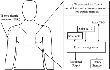
We now describe the design strategy to come to a compact and highly-integrated wireless node that is able to set up a robust, stable, and energy-efficient wireless communication link, and to simultaneously harvest energy from up to three different sources, in order to provide a regulated output for adequately powering the communication system. The architecture of the system is schematically outlined in Fig. 1. The core of the unit is the SIW antenna. The hardware integration strategy consists in reusing the SIW antenna's surface as a platform for the energy harvesting and power management hardware. More specifically, a flexible central power management system (CPMS), including a micro-energy cell (MEC), is deployed on the SIW antenna's backside. The CPMS enables energy harvesting from both indoor artificial light and outdoor solar light by relying on two different flexible solar cells integrated on top of the antenna. Furthermore, thermal body energy harvesting is implemented by including a thermoelectric generator (TEG), placed with its hot side on the human skin, and extending the CPMS with an ultra-low voltage step-up converter. In an IoT scenario where the antenna is integrated into the floor, vibrational energy harvesting based on the piezoelectric effect may be used instead [Reference Jeon, Sood, Jeong and Kim16]. By simultaneously extracting energy from diverse sources, a higher amount of harvested energy can be obtained and the time during which no energy is scavenged, can be reduced.
Block schematic representation of system concept and application.

A) SIW antenna as integration platform
SIW-based antenna topologies leverage a ground plane in combination with vias to achieve a high isolation between the radiating element and its environment. This makes them not only very suitable for comfortable integration into garments or unobtrusive embedding into floors or walls, but also facilitates the integration of additional electronic circuitry without degrading their performance. Subsection (B) will expand on another reason to select SIW-based antennas, being the ease by which additional hardware can be integrated and the ability to minimize the amount and length of interconnections, by exploiting the properties of the topology.
In [Reference Lemey, Declercq and Rogier10], the potential of multiple antenna topologies as integration platform is examined and SIW cavity-backed slot antennas are identified as ideal candidates. Two different SIW cavity-backed slot antennas are therefore presented here. Nevertheless, depending on the application, other SIW-based antennas such as the ones discussed in [Reference Caytan, Lemey, Agneessens, Vande Ginste, Demeester, Loss, Salvado and Rogier15, Reference Agneessens, Lemey, Moro, Bozzi and Rogier17], or [Reference Jin, Li, Alphones and Bao18] may also serve as an integration platform. To illustrate this, we propose a novel compact dual-polarized textile SIW antenna topology that is also an ideal integration platform for energy-harvesting hardware.
1) SFIT SIW CAVITY-BACKED SLOT ANTENNA
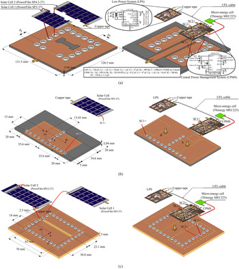
The first topology under study is the wearable SIW cavity-backed textile slot antenna presented in [Reference Moro, Agneessens, Rogier and Bozzi13], which is constructed entirely of textile materials for application in SFIT systems. This topology is depicted in Fig. 2(a) and consists of a conducting feed layer and slot layer, which are patterned in a copper-plated taffeta electrotextile (sheet resistance
 $0.2 \;\Omega / $
sq). The conducting layers are deposited on a dielectric substrate, being a closed cell expanded rubber protective foam layer (dielectric constant ε
r
= 1.495 and loss tangent tanδ = 0.016) with a thickness of 3.94 mm, typically applied in fire fighter jackets. Both conductive fabric layers are glued to the antenna substrate with thermally activated adhesive sheets. They are electrically connected to form an SIW cavity by means of brass eyelets (outer diameter d = 4 mm), which are spaced closely enough to minimize radiation loss (d
x
/d ≤ 2 and d
y
/d ≤ 2) [Reference Bozzi, Georgiadis and Wu11]. The materials from which the on-body antenna is assembled are selected with the greatest care to achieve a flexible, low-profile, and conformal design. The SIW cavity is square and a dog-bone shaped slot is cut out in the top conducting layer. The dimensions of the cavity were selected to excite the TE120 cavity mode at 2.45 GHz; whereas the dimensions of the slot and its position were chosen to obtain optimal coupling with the excited mode. The length of the grounded coplanar waveguide, used as a feed line, was optimized to improve input matching [Reference Moro, Agneessens, Rogier and Bozzi13] within the 2.45 GHz industrial, scientific and medical (ISM) radio band (2.40–2.4835 GHz). More details can be found in [Reference Moro, Agneessens, Rogier and Bozzi13].
Integration strategy illustrated on different SIW antenna topologies: one or two flexible a-Si:H solar cells attached to the upper plane (left), and the proposed flexible power management module, including a micro-energy cell, integrated onto their feed plane (right). (a) The wearable SIW cavity-backed textile slot antenna, as described in [Reference Moro, Agneessens, Rogier and Bozzi13], (b) the novel wearable compact dual-polarized textile SIW antenna, and (c) the SIW cavity-backed slot antenna on cork substrate, as described in [Reference Caytan, Agneessens, Lemey, Vande Ginste, Demeester and Rogier19].

2) SFIT COMPACT DUAL-POLARIZED SIW ANTENNA
We propose a novel wearable textile SIW antenna topology that also acts as an ideal integration platform for energy-harvesting hardware. Depending on the application, this design might be a more appropriate SFIT antenna. The topology, schematically depicted in Fig. 2(b), consists of two rectangular quarter-mode (QM) SIW antennas [Reference Jin, Li, Alphones and Bao18], designated as antennas A and B, which are mirror images of each other about the YZ-plane. The QMSIW cavities are separated by a common via wall, reducing the total number of vias. The dimensions of both QMSIW cavities are chosen such that the resonance frequency of the TE110 mode is 2.45 GHz. Moreover, both QMSIW antennas are designed to be quasi-linearly polarized, along orthogonal directions in the broadside. The plane defined by ϕ = π/4∨ϕ = 5π/4 is the H-plane for antenna A and the E-plane for antenna B; whereas the plane defined by ϕ = 3π/4∨ϕ = 7π/4 is the E-plane for antenna A and the H-plane for antenna B. Both QMSIW cavities are fed by a coaxial probe that efficiently magnetically couples with the TE110 mode. The probe is positioned along the diagonal of the cavity at the optimal location to achieve a −10 dB impedance bandwidth covering the 2.45 GHz ISM-band. Together, both antennas form a compact dual-polarized compound antenna, with ports A and B. This allows the transceiver of the communication system to exploit polarization diversity to combat fading in multipath propagation environments [Reference Vallozzi, Van Torre, Hertleer, Rogier, Moeneclaey and Verhaevert20, Reference Van Torre, Vallozzi, Hertleer, Rogier, Moeneclaey and Verhaevert21]. The same flexible textile materials as for the SFIT SIW cavity-backed slot antenna are used for the construction, being a closed cell expanded rubber protective foam layer for the antenna substrate and a copper-plated taffeta electrotextile for the conducting layers. Again, brass eyelets are applied and the stack is assembled with thermally-activated adhesive sheets.
3) IOT ULTRA-WIDEBAND (UWB) SIW CAVITY-BACKED SLOT ANTENNA ON CORK SUBSTRATE
The final topology we discuss is the wideband SIW cavity-backed slot antenna, presented in [Reference Caytan, Agneessens, Lemey, Vande Ginste, Demeester and Rogier19]. Cork is applied as a substrate material, enabling seamless integration in floors or walls. Figure 2(c) schematically depicts this topology, which consists of a conducting slot layer and a ground plane, again patterned in copper-plated taffeta electrotextile and glued to the cork substrate with thermally activated adhesive sheets. Appropriately spaced brass eyelets electrically connect the two conducting layers to form the rectangular SIW cavity. The substrate is an ordinary off-the-shelf cork layer for floor or wall finishing with a thickness of 3 mm, provided by Amorim Cork Composites S.A. Its dielectric constant and loss tangent were characterized [Reference Caytan, Agneessens, Lemey, Vande Ginste, Demeester and Rogier19] by a combination of a non-resonant and a resonant method, indicating that the material is slightly inhomogeneous, with an average dielectric constant of ε r = 1.23 and loss tangent of tanδ = 0.0263. The design is performed using the average parameters, while maintaining some impedance bandwidth margins to allow for varying cork material properties. This topology applies the multi-moding bandwidth enhancement method [Reference Luo, Hu, Li, Zhang, Sun and Zheng22] by using as the radiating element a non-resonant slot in the top patch, much longer than half a wavelength. This almost splits the SIW cavity into two half-cavities, leading to the simultaneous excitation of two hybrid cavity modes. Appropriate dimensioning of the half-cavities and slot leads to resonance frequencies of the two excited hybrid modes that are close together in the frequency band of interest, enlarging the impedance bandwidth. The slotted SIW cavity is fed by a coaxial probe, positioned to achieve a −10 dB impedance bandwidth that covers the lower 500 MHz (3.1–3.6 GHz) of the 3.1–10.6 GHz band, allocated to UWB transmission systems by the Federal Communications Commission [Reference Dardari, D'Errico, Roblin, Sibille and Win23]. Simulations predict and measurements confirm [Reference Caytan, Agneessens, Lemey, Vande Ginste, Demeester and Rogier19] that the maximum gain and the other far-field properties only vary slightly over the considered frequency band, which is a key requirement to UWB antennas.
B) Energy harvesting and power management hardware
The discussed SIW antennas are then exploited as hybrid energy harvesting and power management platforms, by deploying a flexible power management module and a 170
 ${\rm \mu}$
m-thick MEC (capacity
 $130\,{\rm \mu A h}$
) on their feed plane and one or two ultra-flexible 200
 ${\rm \mu}$
m-thick PowerFilm thin film a-Si:H solar cells on their upper plane, attached by stretchable adhesive sheets. This is shown schematically in Figs 2(a)–2(c). The SIW structure of the antennas allows us to minimize the amount and length of interconnections. Therefore, we exploit the SIW cavity as a common DC ground for the energy-harvesting hardware and use the hollow eyelets to route the positive connection of the solar cells to the power management system.
The proposed power management system consists of two interconnected subsystems, being the low-power system (LPS) and the CPMS. To maintain mechanical flexibility of the entire module, the LPS and CPMS are etched on a flexible, ultra-thin polyimide substrate. Moreover, small electronic components were used and distributed over a larger area than necessary. The CPMS is based on the MAX17710 integrated circuit (IC) from Maxim Integrated. It is designed to charge the MEC from two high-voltage DC sources, through linear harvesting, and one low-voltage DC source, via a boost converter. In the meantime, the CPMS protects the MEC and provides a regulated output voltage. Energy harvesting from artificial and solar light is then enabled by connecting solar cell 1 (PowerFilm SP3-37) to the boost converter input and solar cell 2 (PowerFilm SP4.2-37) to a linear harvesting input, respectively. We note that the upper plane of the compact dual-polarized SIW antenna, as shown in Fig. 2(b), only provides room for solar cell 1. The LPS is built around the LTC3108 IC by Linear Technology. It implements an ultra-low voltage step up converter, with its output connected to the second linear harvesting input of the CPMS, to enable thermal body energy harvesting via an externally connected TEG. The TEG is not integrated onto the antenna, to obtain a higher degree of freedom. In this work, a single TEG is connected to the LPS. Specifically, the UltraTec Series UT6,24,F1,5555 component by Laird Technologies is selected [Reference Lemey, Declercq and Rogier10]. Its hot side is tightly attached to the skin of the wearer's arm, whereas its cold side is exposed to the ambient air, in order to harvest thermal body energy based on Seebeck's effect [Reference Lossec, Multon, Ahmed and Goupil8]. However, multiple TEGs, potentially stacked, or a heat sink could be used to further increase the amount of harvested energy. In a floor or wall integration scenario, being the typical deployment configuration of the UWB SIW cavity-backed slot antenna on cork substrate, thermal energy harvesting may not be relevant. Then, vibrational energy harvesting based on the piezoelectric effect may be used instead [Reference Jeon, Sood, Jeong and Kim16].
To ensure stable performance of the SIW antennas after hardware integration, the solar cells are attached to the conducting parts of the antenna without extending beyond them and without covering the radiating element. In the case of the textile SIW cavity-backed slot antenna (Fig. 2(a)), the two flexible solar cells were therefore patterned to fit the antenna's slot. Furthermore both flexible circuit boards were oriented such that the feed line remains uncovered. Both the compact dual-polarized SIW antenna (Fig. 2(b)) and the UWB SIW cavity-backed slot antenna on cork substrate (Fig. 2(c)) are fed by a coaxial probe, and they use either a rectangular slot or no slot at all, making the above considerations irrelevant for them.
III. MEASUREMENT RESULTS
A) Figures of merit of the SIW antennas
First, the integration procedure is validated by verifying that the performance of the SIW antennas, discussed in Section II, remains nearly undisturbed by the integrated hardware. Therefore, the reflection coefficient and the far-field gain pattern of all discussed SIW antennas were measured and compared at different stages of hardware integration, more specifically before the integration of any hardware, after solar cell integration, and when all energy harvesting and power management hardware is integrated and all connections are made according to Figs 2(a)–2(c). All measurements are conducted inside an anechoic room mimicking free-space conditions, by means of an Agilent N5242A PNA-X Microwave Network Analyzer and an Orbit/FR DBDR antenna positioning system. The far-field gain patterns are measured by the gain comparison method using the MI-12 standard gain horn series.
1) SFIT SIW CAVITY-BACKED SLOT ANTENNA
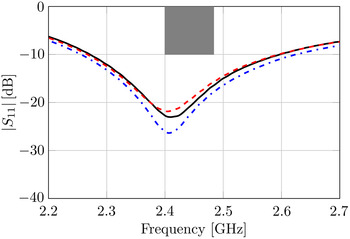
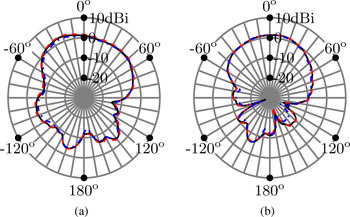
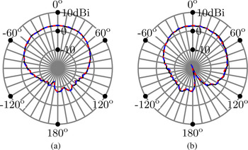
Figure 3 shows the input reflection coefficient from 2.2 to 2.7 GHz, whereas Fig. 4 shows the gain patterns in the E- and H-plane at 2.45 GHz, for all three stages of hardware integration. These measurements show that the integration of the solar cells, the flexible power management system and MEC, only has a negligible influence on the antenna's performance. Hence, they prove that this topology is indeed very suitable as an integration platform, reducing the amount and length of interconnecting wires by exploiting its excellent antenna/environment isolation. The antenna's outstanding on-body performance was already demonstrated in [Reference Moro, Agneessens, Rogier and Bozzi13].
Measured input reflection coefficient |S 11 | (dB) versus frequency of the wearable SIW cavity-backed slot antenna for different stages of hardware integration. Undisturbed antenna (—), solar cells integrated (– – –), and all energy-harvesting hardware integrated (–.–.).

Measured far-field gain pattern (dBi) of the wearable SIW cavity-backed slot antenna at 2.45 GHz in both (a) the E-plane and (b) the H-plane. Undisturbed antenna (—), solar cells integrated (– – –), and all energy-harvesting hardware integrated (–.–.).

2) SFIT COMPACT DUAL-POLARIZED SIW ANTENNA
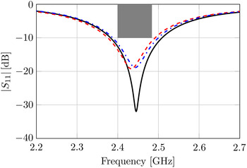
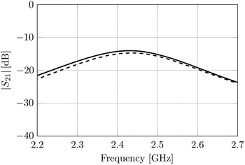
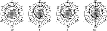
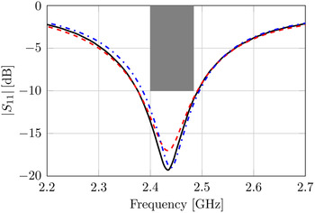
Figure 5 compares the simulated and measured free-space input reflection coefficients, for both ports A and B. The slight difference is caused by fabrication inaccuracies. The impedance bandwidth of both antenna ports covers the entire 2.45 GHz ISM-band (2.40–2.4835 GHz). Figure 6 shows that the isolation between port A and B is larger than 14 dB in the entire 2.45 GHz ISM-band. Figures 7(a)–7(d) show the simulated and measured far-field gain patterns for ports A and B, in the E-plane and H-plane at 2.45 GHz. The most important performance parameters, measured at 2.45 GHz for both ports A and B, are listed and compared to the simulation values in Table 1. These include the radiation efficiency, the FTBR (defined as the ratio of the gain in the +z-direction to the gain in the –z-direction), the maximum gain, and the polarization properties of the broadside radiation, being the tilt angle α of the polarization ellipse (defined as the angle between the x-axis and the major axis of the ellipse), and its axial ratio (defined as the ratio of the major axis to the minor axis with a positive sign indicating right-hand elliptical polarization). In general, a good agreement between measurement and simulation is observed. We again confirm that the integrated hardware does not disturb the properties of the SIW antenna. Indeed, the input reflection coefficient for port A, shown in Fig. 8, and the far-field gain patterns in the E- and H-plane at 2.45 GHz for port A, shown in Fig. 9, are nearly identical for all three stages of hardware integration. Table 1 also lists the radiation efficiency, FTBR, maximum gain and broadside polarization properties for port A, at different stages of hardware integration. Only the axial ratio is slightly degraded by the integrated hardware, while the other values remain constant, within the experimental error.
Simulated (—) and measured input reflection coefficient |S 11 | (dB) versus frequency for ports A (– – –) and B (–.–.) of the dual-polarized SIW antenna.

Simulated (—) and measured (– – –) transmission coefficient |S 21 | (dB) versus frequency between ports A and B of the dual-polarized SIW antenna.

Far-field gain pattern (dBi) of the dual-polarized SIW antenna at 2.45 GHz, for port A in (a) the E-plane and (b) the H-plane; and for port B in (c) the E-plane and (d) the H-plane. Simulation (—) and measurement (– – –).

Measured input reflection coefficient |S 11 | (dB) versus frequency for port A of the dual-polarized SIW antenna for different stages of hardware integration. Undisturbed antenna (—), solar cell integrated (– – –), and all energy-harvesting hardware integrated (–.–.).

Measured far-field gain pattern (dBi) for port A of the dual-polarized SIW antenna at 2.45 GHz, in both (a) the E-plane and (b) the H-plane. Undisturbed antenna (—), solar cell integrated (– – –), and all energy-harvesting hardware integrated (–.–.).

Measured (simulated) antenna characteristics at 2.45 GHz for ports A and B of the dual-polarized SIW antenna.

3) IOT UWB SIW CAVITY-BACKED SLOT ANTENNA ON CORK SUBSTRATE
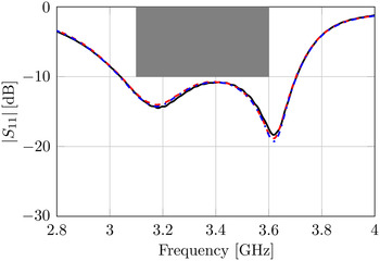
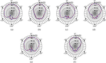
Figure 10 shows the input reflection coefficient from 2.8–4.0 GHz, whereas Fig. 11 shows the gain patterns in the E- and H-plane at the lower frequency 3.10 GHz, the center frequency 3.35 GHz and the upper frequency 3.60 GHz, for all three stages of hardware integration. These measurements confirm that the hardware integration only has a minor influence on the antenna's performance and that this topology serves as an excellent hardware integration platform.
Measured input reflection coefficient |S 11 | (dB) versus frequency of the SIW cavity-backed slot antenna on cork substrate for different stages of hardware integration. Undisturbed antenna (—), solar cells integrated (– – –), and all energy-harvesting hardware integrated (–.–.).

Measured far-field gain pattern (dBi) of the SIW cavity-backed slot antenna on cork substrate at the lower frequency 3.10 GHz, in (a) the E-plane and (b) the H-plane, at the center frequency 3.35 GHz, in (c) the E-plane and (d) the H-plane, and at the upper frequency 3.60 GHz, in (e) the E-plane and (f) the H-plane. Undisturbed antenna (—), solar cells integrated (– – –), and all energy-harvesting hardware integrated (–.–.).

B) Energy supplied by the hybrid energy-harvesting system
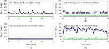
Finally, four well-chosen scenarios, each lasting 20 min, are studied in a realistic indoor environment to demonstrate the energy-harvesting potential of our system in low-power density situations. In each scenario, a test person, with a height of 1.87 m, wears the compact, highly-integrated and unobtrusive unit on his chest and the selected TEG on his left arm. During each 20 min interval, the power scavenged by each of the three energy harvesters is measured as well as the effectively delivered power to the MEC. Yet, only the power delivered by solar cell 1, the TEG and the sum of both are depicted in Figs 12(a)–12(d), as it turned out that solar cell 2, in combination with the linear harvesting technique, was not able to harvest energy in these indoor scenarios.
Power generated by the TEG (blue solid line), solar cell 1 (green solid line), and the sum of both (black solid line), as a function of time, for each of the four considered realistic indoor scenarios.

The first scenario comprises a test person sitting in a 2.4 m high room with a uniform temperature of 15°C, no active light sources and no air circulation. Figure 12(a) shows that the thermal gradient between room and skin temperature is high enough to harvest energy via the TEG, whereas the absence of light prevents solar cell 1 from scavenging energy. The peaks in scavenged energy by the TEG can be attributed to stretching of the wearer. On average, the TEG was able to generate
 $108.6\, {\rm \mu W}$
, of which
 $39.2\, {\rm \mu W}$
was effectively delivered to the MEC, leading to an overall system efficiency η of 36.1%.
The second scenario is very similar to the first scenario. However, in the second scenario, fluorescent lamps mounted at the ceiling are turned on and the test person is standing in an upright position. As shown in Fig. 12(b), the TEG and solar cell 1 are now both able to harvest energy. On average,
 $106.7 {\rm \,\mu W}$
is recovered by the TEG and
 $33.2 {\rm \,\mu W}$
by solar cell 1, resulting in a total harvested power of
 $139.9 {\rm \,\mu W}$
. Eventually,
 $60.6 {\rm \,\mu W}$
was stored in the MEC, corresponding to
 $\eta = 43.2\% $
.
In the third scenario, the room is heated up to 25°C. Figure 12(c) indicates that the room temperature is too high for the TEG to recover energy and that only solar cell 1 is capable of harvesting energy. Solar cell 1 produced
 $37.0 {\rm \,\mu W}$
on average, of which
 $24.4 {\rm \,\mu W}$
is effectively stored by the MEC.
In scenario 4, the test person is walking in a corridor with a height of 2.2 m, a steady temperature of 18°C, no air circulation and similar fluorescent lights at the ceiling. Figure 12(d) clearly demonstrates that, as a result of the dynamic nature of the wearer and the corresponding increase in convection, the power generation by the TEG is substantially increased. Drops in generated power by the TEG and solar cell 1 can be attributed to pauses in which the test person stops walking and the distance between subsequent lamps, respectively. During this 20-min interval,
 $296.0 {\rm \,\mu W}$
and
 $34.8 {\rm \,\mu W}$
were generated by the TEG and solar cell 1 on average, respectively. This resulted in a total average power of
 $152.17 {\rm \,\mu W}$
that could be effectively harvested, leading to
 $\eta = 46.0\% $
.
Figures 12(a)–12(d) clearly evince the necessity of hybrid energy harvesting in real-life scenarios. Figures 12(a) and 12(c) show that no power would have been harvested if the user only relied on either solar cell 1 or the TEG, respectively. Hence, it reduces the periods during which no energy is harvested. Figure 12(b) depicts that hybrid energy harvesting may result in a higher amount of scavenged energy by combining the energy harvested from diverse energy sources. Both effects could lead to either a higher system autonomy or reduced battery size. An even higher amount of energy could be recovered by solar cell 1 and the TEG in outdoor environments thanks to improved convection and light conditions. In addition, in such an environment, solar cell 2 is also able to scavenge energy. More specifically, in case of a turbidity-free sky, placing solar cell 2 perpendicular to the earth surface, pointed in the direction of the sun should enable harvesting an additional 49 mW [Reference Lemey, Declercq and Rogier10].
IV. CONCLUSION
In this paper, we discussed the integration on an SIW antenna of up to three energy harvesters, including two flexible solar cells and a TEG, together with a MEC and a corresponding flexible power management system. The total system is intended for garment integration or embedding in floor or wall materials. Two different SIW cavity-backed slot antennas and a novel compact dual linearly polarized SIW antenna topology were proposed to serve as platforms for this additional hardware. The pursued integration procedure minimizes the hardware's influence on antenna performance and, in the meantime, guarantees wearability or unobtrusive floor/wall integration. Measurements prove that the selected SIW antennas are indeed suitable as integration platforms; whereas experiments in four carefully selected realistic indoor environments demonstrated that a hybrid energy-harvesting approach leads to a higher amount of energy, scavenged in a more continuous way.
ACKNOWLEDGEMENT
Part of the work was supported by the iMinds IoT research program.
 Olivier Caytan was born in 1990. He received his M.Sc. degree in Electrical Engineering from Ghent University, Ghent, Belgium in 2014. Since October 2014, he has been working as a Ph.D. student at the Electromagnetics group in the Department of Information Technology (INTEC) at Ghent University. His research focuses on the design of low-profile antennas for integration in textile, floor or wall materials, in the context of internet of things applications.
 Sam Lemey was born in 1990. He received his M.Sc. degree in Electronic Engineering from Ghent University, Campus Kortrijk, Belgium, in 2012. Since September 2012, he has been working toward the Ph.D. degree in the Electromagnetics Group, Department of Information Technology (INTEC), Ghent University. His research activities focus on the design of textile antennas for smart fabric interactive textile systems, the reuse of textile antennas as hybrid energy harvesting and power management platforms, new techniques for implementing substrate integrated waveguide (SIW) structures in textile materials, and ultra-short range multiple-input multiple-output wireless communication (MIMO).
 Sam Agneessens (M 2014) was born in Belgium in 1986. He received his M.S. and Ph.D. degrees in Electrical Engineering from the University of Ghent, Ghent, Belgium, in 2011 and 2015. He is presently a FWO postdoctoral fellow within the Electromagnetics group in the Department of Information Technology (INTEC) at Ghent University. His research focuses on the design and development of textile antennas for wearable applications and integrated mm-wave antennas. Sam Agneessens received the URSI Young Scientist Award at the 2014 URSI General Assembly and is co-recipient of the 2014 Premium Award for Best Paper in IET Electronics Letters.
 Hendrik Rogier received his Electrical Engineering and the Ph.D. degrees from Ghent University, Gent, Belgium, in 1994 and in 1999, respectively. He is a Full Professor at the Department of Information Technology, iMinds/Ghent University. From October 2003 to April 2004, he was a Visiting Scientist at the Mobile Communications Group of Vienna University of Technology. He authored and coauthored about 125 papers in international journals and about 140 contributions in conference proceedings. He is an Associate Editor of IET Electronics Letters and a member of the Editorial Board of IET Science, Measurement Technology. His present research interests are antenna systems, radiowave propagation, body-centric communication, numerical electromagnetics, electromagnetic compatibility, and power/signal integrity. He was twice awarded the URSI Young Scientist Award. Moreover, he received the 2014 Premium Award for Best Paper in IET Electronics Letters and several awards at conferences. He is a Senior Member of the IEEE.