1. Introduction
Over the past few decades, significant progress has been made in robotic hand research [Reference Jin1–Reference Tang, Yu, Sun, Li, Sarkodie-Gyan and Li5]. In order to achieve compliant grasping of unstructured objects while reducing damage to the grasped items, various adaptive and compliant grippers have been proposed, including reconfigurable fingered grippers, bio-inspired hybrid fingers, and passive form-sensing mechanisms [Reference Zhou, Chen, Chang, Lu, Leung, Chen, Hu and Wang6–Reference El-Sayed and Yan13].
For example, some designs employ pneumatic or torsional methods to enhance wrapping forces for grasping unstructured objects [Reference Shan, Zhao, Yu, Pei, Jin and Sun14–Reference Jiao, Ji, Zou, Yang and Pan16], while others adopt swallowing techniques [Reference Guan, Liu, Sun, Wang, Guo, Liu and Leng17]. Variable-stiffness approaches, such as layer jamming or granular jamming, are utilized to modulate the stiffness of soft robotic hands and enhance grasping force [Reference Wei, Shan, Zhao, Qi and Zhao18–Reference Hoang, Quek, Thai, Phan, Lovell and Do21]. Additionally, hybrid schemes that combine rigid mechanisms with soft structures are employed to achieve rigid–soft coupled grasping [Reference Yin, Li, Niu and Xu11, Reference Zhu, Chai, Yong, Xu, Guo, Ding and Wu22–Reference Wang, Xiong, Zi, Qian, Wang and Zhu24]. Furthermore, some designs mimic the structure of octopus arms or their suction mechanisms for grasping [Reference Hao, Xiao, Liu, Zhang and Ma25–Reference Tramacere, Beccai, Kuba, Gozzi, Bifone and Mazzolai27]. Enveloping and swallowing grippers can achieve stable grasping for objects smaller than the gripper cavity, but their effectiveness is strongly constrained by geometric scale. Variable-stiffness methods, such as granular jamming and layer jamming, enhance post-contact holding force, yet they still rely on sufficient initial contact and are less effective for large smooth objects. Hybrid rigid–soft grippers improve force transmission but often require increased structural complexity and active control.
In contrast, suction-based grasping inspired by octopus suckers [Reference Sandoval, Ishida, Jadhav, Huen and Tolley28, Reference Pan, Zhou, Zhang, Zhang, Hu, An, Liu and Ma29] offers distinct advantages. Vacuum suction is generated, either actively or passively, to form a negative pressure between the gripper and the target object, thereby firmly adhering the object. This adhesion mechanism is independent of object size; as long as a sealed vacuum cavity is formed and sufficient suction force is generated, any object can, in theory, be grasped. However, the suction force provided by a single suction cup is inherently limited; even with a perfect vacuum, the maximum achievable suction force remains constrained by atmospheric pressure (i.e., one atmosphere).
When grasping heavy or large objects to ensure stable adhesion, multiple suction cups are typically employed simultaneously to amplify the overall suction force. Multi-suction grasping is widely applied in industrial production lines [Reference Monkman, Hesse, Steinmann and Schunk30], where the number of suction cups is determined by the size and weight of the target object. When an array designed for large objects is used to grasp a smaller object, some suction cups inevitably experience air leakage, leading to insufficient adhesion and limiting their application in complex grasping tasks. Some researchers have attempted to overcome this issue by sealing suction cups with flexible membranes that deform to create a cavity between the cup and the object to generate negative pressure [Reference Takahashi, Suzuki and Aoyagi31–Reference Mazzolai, Mondini, Tramacere, Riccomi, Sadeghi, Giordano, Del Dottore, Scaccia, Zampato and Carminati33]. Although this method prevents leakage, it poses significant challenges regarding the durability of the flexible membrane, and because it relies on membrane deformation, complete contact between the membrane and the object’s surface is required; any gap can easily lead to suction failure [Reference Koivikko, Drotlef, Dayan, Sariola and Sitti34].
To overcome the leakage, inadequate sealing, and unstable adhesion commonly encountered in conventional multi-cup suction systems, this paper proposes an adaptive suction gripper with passive self-closing and leakage-prevention functionality. Unlike membrane-based sealing approaches, actively controlled valve systems, or bio-inspired suction cups relying on complex actuation, the proposed design employs a fully passive elastic-ball mechanism that autonomously closes failed suction channels according to local airflow conditions. The proposed design introduces a passive self-closing suction unit for local leakage isolation, enables distributed leakage tolerance in multi-cup arrays, and integrates these units with an adaptive body for grasping objects of varying geometries. This passive pneumatic-mechanical architecture significantly improves the practicality and robustness of suction grasping in complex environments.
Structural design of the adaptive suction gripper. (a) The proposed adaptive suction gripper. (b) Adaptive stiffness modulation process of the gripper. (c) Suction cup normally adheres to the object’s surface. (d) The suction cup automatically closes when it fails to adhere to the object’s surface.

Figure 1. Long description
Panel A: A diagram of an adaptive suction gripper showing its components. The diagram includes a transmission air tube, external air source, guide rod suction hole, base, variable-stiffness flexible sleeve, rigid pellet, self-closing suction cup, rope, and elastic ball. Panel B: A diagram illustrating the adaptive stiffness modulation process of the gripper. It shows the gripper in contact with objects and the self-adaptive and stiffness enhancement process. Panel C: A diagram showing the suction cup normally adhering to the object’s surface with negative press and vacuum. Panel D: A diagram showing the suction cup automatically closing when it fails to adhere to the object’s surface, with negative press and vacuum indicated.
2. Design and fabrication
2.1. Working principle of the adaptive suction gripper
Our adaptive suction gripper is primarily composed of the Variable-Stiffness Adaptive Mechanism (VSAM), the Self-closing Suction Cup (SCS), and the Transmission Air Tube (TAT), as shown in Figure 1(a). The VSAM consists of a Variable-Stiffness Flexible Sleeve (VSFS) and rigid particles. Suction force is generated by the SCS, shape adaptation is achieved by the VSAM, and the TAT connects the VSAM and SCS to the external air source. Owing to the mobility of the rigid particles and the flexibility of the VSFS, the VSAM automatically conforms to the object’s shape upon contact. Moreover, once shape adaptation is completed, a vacuum is applied to utilize the jamming effect of the particles, thereby increasing the overall stiffness of the mechanism and enhancing the grasping force, as shown in Figure 1(b).
The SCS units are uniformly distributed along the bottom of the VSAM and are fixedly attached to it. Because the SCS is also a flexible structure, it automatically conforms to the fine-scale undulations of the object’s surface, thereby increasing the contact area between the SCS and the target. Additionally, each VSAM contains an elastic ball that automatically adjusts the suction capability of each suction cup according to the gas flow velocity. When a suction cup is completely separated from the target object, the gas flow velocity between the suction cup and the elastic ball reaches its maximum, thereby lifting the elastic ball to block the airflow and prevent leakage, as shown in Figure 1(c). Conversely, when the suction cup is in full contact with the target object, a sealed cavity is formed between them, causing the internal gas flow velocity within the suction cup to gradually decrease. Under these conditions, the elastic ball is not lifted to block the airflow, allowing the suction cup to effectively adhere to the target object, as shown in Figure 1(d). The operation of the self-closing mechanism is primarily governed by airflow-induced lifting of the elastic ball and gravity-assisted resetting. Therefore, the gripper is not restricted to strictly vertical grasping orientations. The constrained motion of the elastic ball enables reliable operation under different installation orientations.
Fabrication of an adaptive suction gripper. (a) Physical picture of adaptive suction gripper. (b) Make molds for VSAM. (c) SCS fabrication and assembly.

2.2. Fabrication of the adaptive suction gripper
The rigid components of the gripper consist of the TAT, base, and metal connectors, as shown in Figure 2(a). The TAT and Base are fabricated via 3D printing, and the metal connectors are standard M5 hexagon socket head cap screws. Molds for the VSFS are produced, as shown in Figure 2(b), and the VSFS is formed via silicone injection molding. For the fabrication of the SCS, a sewing thread is first passed through the center of an elastic ball; one end is knotted to prevent detachment, while the other end is threaded through a flexible suction cup (DP-25, KAIRUISI) and secured by a fixation column, thereby forming an SCS unit. Nine SCS units are then assembled onto the VSFS, as depicted in Figure 2(c). Subsequently, plastic pellets with a diameter of 7.2 mm are added into the VSFS until it is completely filled, forming the VSAM. Finally, the TAT, base, and screws are assembled with the VSAM already equipped with the SCS units, thereby completing the fabrication of the adaptive suction gripper, as shown in Figure 2(a).
The selected materials and fabrication methods were chosen by considering sealing performance, structural rigidity, manufacturability, and rapid prototyping efficiency. The TAT and base were fabricated by 3D printing to enable rapid geometric iteration and low-cost customization during prototype development. Silicone was used for the VSFS because of its high compliance, elastic recovery, and ability to conform to irregular contact surfaces while maintaining airtight sealing. Commercial suction cups were adopted to ensure dimensional consistency and reliable suction behavior. Plastic pellets were selected as the granular medium due to their low cost, light weight, and stable jamming response under vacuum conditions.
To reduce manufacturing variability, all printed components were fabricated using identical printer settings, and all SCS units were assembled with consistent thread length and elastic-ball positioning. These measures ensured repeatable structural geometry and suction functionality across prototypes.
3. Mechanical analysis of the SCS
To provide a rigorous theoretical foundation for the self-closing and leakage prevention mechanism, the following assumptions are established:
-
• Quasi-steady airflow approximation: The airflow field is assumed to adjust rapidly compared with the ball motion, allowing the aerodynamic force to be evaluated based on the instantaneous ball position. The transient ball motion is subsequently described using the equation of motion.
-
• Locally incompressible flow approximation: The baseline model employs the incompressible Bernoulli equation to derive the aerodynamic lifting force. The influence of compressibility is further evaluated in Section 3.3 using the local Mach number and an isentropic compressible-flow correction.
-
• Energy-based triggering criterion: The net aerodynamic work over the lifting path is used to determine whether the ball can reach the suction orifice. A non-negative net work (ΔW ≥ 0) indicates that the aerodynamic work is sufficient to overcome the gravitational potential-energy increase.
-
• Geometric assumptions: The internal geometry is designed to provide sufficient clearance between the elastic ball and the suction-cup wall during lifting, and sustained wall contact and friction are therefore neglected. Upon reaching the closing position, the ball is assumed to seal the suction orifice, while local deformation and seating effects are not explicitly modeled.
To ensure the unhindered dynamic movement of the elastic ball and the validity of the fluidic model, the following geometric constraints are imposed: The diameter of the elastic ball
 $(2r_{b})$
must be smaller than the width of the suction waist (
 $l_{CD}$
) to prevent mechanical jamming and maintain a continuous airflow channel (
 $2r_{b}\lt l_{CD}$
).
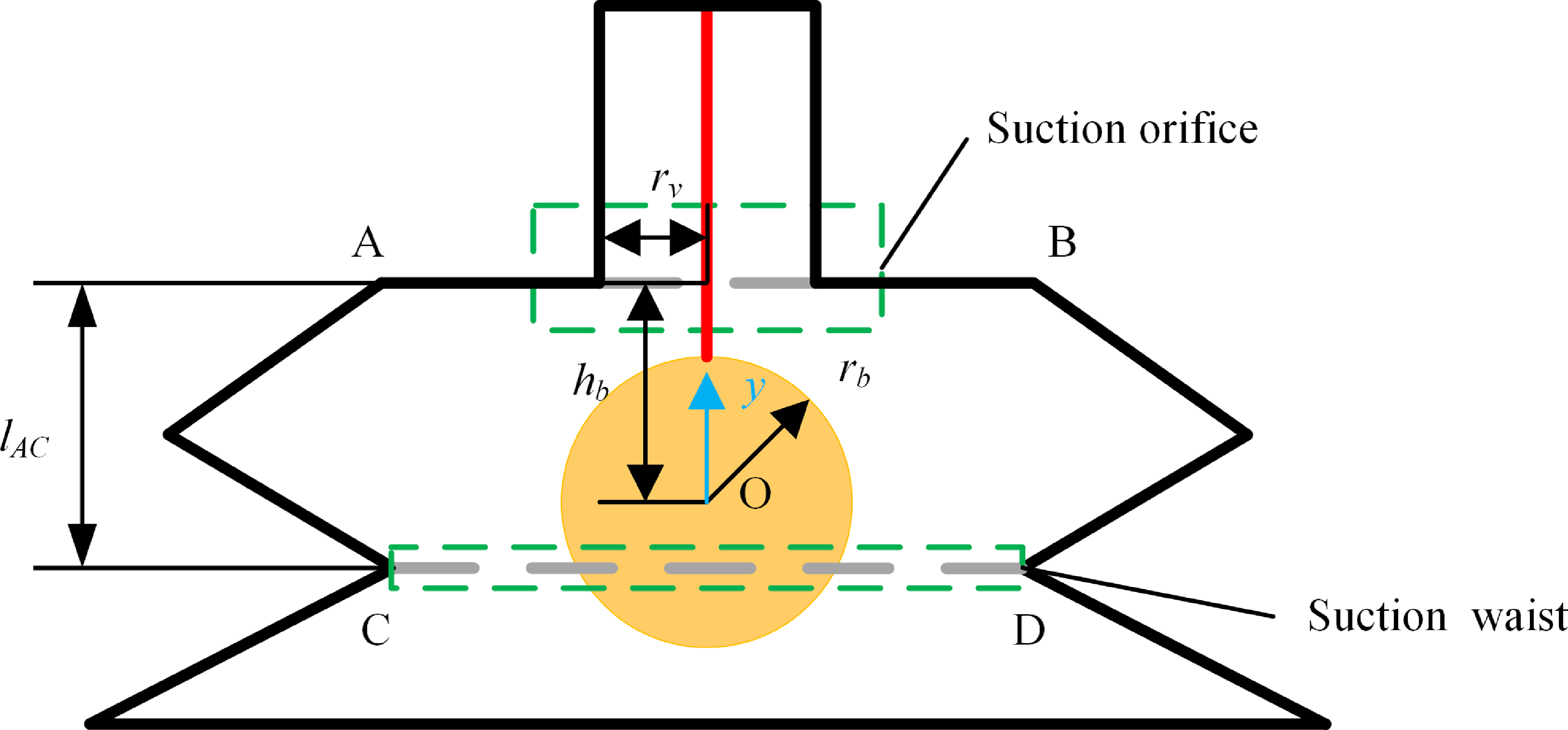
In the adaptive suction gripper designed in this work, SCS units are endowed with self-closing and leakage prevention properties. For theoretical analysis, a representative SCS under the leakage state is considered with a prescribed volumetric flow rate Q, as shown in Figure 3.
Geometric analysis of SCS in the adaptive vacuum gripper.

3.1. Closing condition under leakage state
When a suction cup fails to establish contact with the target surface, ambient air continuously enters the cavity, resulting in a high airflow velocity through the internal channels. The pressure gradient across the elastic ball generates an upward aerodynamic lift.
The energy criterion for the ball to reach the suction orifice is obtained from the work–energy relation. Assuming that the ball starts from rest, the net work performed by the aerodynamic force and gravity over the lifting distance is:
 \begin{equation} {\unicode[Arial]{x0394}} W=\int_{0}^{y}\left(F_{v}-mg\right)dy\geq 0,0\leq y\leq h_{b} \end{equation}
Where F v is the aerodynamic force acting on the ball, m is the mass of the elastic ball, g is the gravitational acceleration, h b is the initial vertical distance between the center of the ball and the suction orifice.
When ΔW ≥ 0, the aerodynamic work is sufficient to overcome the gravitational potential-energy increase, and the ball can reach the suction orifice. Conversely, ΔW
 $ \lt $
0 indicates that the available aerodynamic work is insufficient to complete the closing motion.
The suction force is given by:
 \begin{equation} F_{v}={\unicode[Arial]{x0394}} pS_{b} \end{equation}
where Δp is the pressure difference between the upper and lower surfaces of the elastic ball, and
 $S_{b}=\pi {r}_{b}^{2}$
is the cross-sectional area of the elastic ball. According to Bernoulli’s principle:
 \begin{equation} {\unicode[Arial]{x0394}} p=\frac{1}{2}\rho ({v_{1}}^{2}-{v_{2}}^{2}) \end{equation}
where v
1 and v
2 represent the flow velocities at the narrow suction orifice and the waist of the suction cup, respectively, and
 $ \rho $
is the air density. Based on the continuity equation:
 \begin{equation} Q=S_{1}v_{1}=S_{2}v_{2} \end{equation}
where Q represents the volumetric flow rate.
 $S_{1}={\unicode[Arial]{x03C0}} {r}_{v}^{2}$
is the area of the suction orifice, and
 $S_{2}(y)$
is the instantaneous minimum annular cross-sectional area between the ball and the suction waist at height y:
 \begin{equation} S_{2}(y)={\unicode[Arial]{x03C0}} \left(\frac{{l}_{CD}^{2}}{4}-{r}_{b}^{2}+\left(l_{AC}-h_{b}+y\right)^{2}\right) \end{equation}
Where l AC is the reference distance between points A and C.
By combining Eqs. (2)–(4) the fully expanded expression for the suction force is derived as:
 \begin{equation} F_{v}(y)=\frac{\rho Q^{2}{r}_{b}^{2}}{2\pi }\left[\frac{1}{{r}_{v}^{4}}-\frac{1}{\left(\frac{{l}_{CD}^{2}}{4}-{r}_{b}^{2}+\left(l_{AC}-h_{b}+y\right)^{2}\right)^{2}}\right] \end{equation}
Substituting Eqs. (6)–(1), yields the closed-form analytical solution for the self-sealing function.
3.2. Opening condition under sealed contact state
When the suction cup establishes sealed contact with the object surface, the incoming airflow and the corresponding aerodynamic lifting force decrease substantially. If the available aerodynamic work is insufficient to raise the ball to the suction orifice,
 \begin{equation} {\unicode[Arial]{x0394}} W\lt 0 \end{equation}
Under this condition, the self-closing condition is not satisfied. The suction channel therefore remains open, allowing the vacuum pressure to be transmitted to the sealed suction interface.
3.3. Quantitative assessment of model simplifications
The analytical model described above is primarily intended to predict the triggering condition of the self-closing mechanism while retaining a tractable closed-form representation. To clarify the validity and applicable range of the model, the effects associated with ball–wall friction, transient ball motion, and airflow compressibility are further assessed below.
3.3.1. Ball–wall friction
The neglect of ball–wall friction is based on the geometric clearance of the SCS rather than on an assumption of a small friction coefficient. Specifically, the lifting distance hbh_b and the internal profile of the suction cup are selected such that sufficient radial clearance is maintained between the elastic ball and the inner wall throughout the principal lifting motion. This geometric condition can be expressed as
 \begin{equation} R_{\min }(y)-r_{b}\gt 0,\,\begin{array}{l} \end{array}0\leq y\leq h_{b} \end{equation}
where
 $R_{\min }(y)$
denotes the minimum radial distance from the suction-cup centerline to the inner wall at the instantaneous ball position. Under this geometric-clearance condition, no sustained ball–wall contact occurs during the principal lifting stage. Therefore, the wall normal force associated with the inner wall is N = 0, and the corresponding Coulomb sliding-friction force and friction work are zero.
Therefore, no ball–wall sliding-friction term is required in the work criterion of Eq. (1) for the modeled lifting stage. It should be noted that short-duration contact and local elastic deformation may occur when the ball reaches the suction orifice and forms the final seal. These local seating effects are not explicitly resolved by the present analytical model.
3.3.2. Transient response of the elastic ball
Although the airflow field is treated quasi-steadily with respect to the instantaneous ball position, the elastic ball possesses finite mass and therefore exhibits a transient response during closing. Rather than neglecting its kinetic energy, the ball motion can be described by
 \begin{equation} m\frac{d^{2}y}{dt^{2}}=F_{v}(y)-mg \end{equation}
with the initial conditions
 \begin{equation} y(0)=0, \quad \dot{y}(0)=0 \end{equation}
According to the work–energy relation, the instantaneous ball velocity can equivalently be expressed as
 \begin{equation} \dot{y}(y)=\sqrt{\frac{2}{m}\int_{0}^{y}[F_{v}(\xi )-mg]d\xi } \end{equation}
where
 $ \xi $
is the integration variable. Accordingly, the theoretical closing time required for the ball to travel from its initial position to the suction orifice is
 \begin{equation} t_{c}(h_{b})=\int_{0}^{h_{b}} \frac{dy}{\sqrt{\dfrac{2}{m}\displaystyle \int_{0}^{y}[F_{v}(\xi )-mg]d\xi }} \end{equation}
The theoretical closing time is therefore a function of the lifting distance h b , as given by Eq. (12). This relationship enables the transient closing response to be quantitatively evaluated for different geometrically admissible values of h b , without introducing an additional quasi-static assumption for the ball motion.
Parameters of the suction cup, elastic ball, and pneumatic pump.

Table I. Long description
The table presents parameters of a suction cup, elastic ball, and pneumatic pump. It has three columns and two rows. The columns are labeled Name, Suction cup, Elastic ball, and Pneumatic pump. The row labeled Variables lists rv(mm), lAC(mm), lCD(mm), m(g), rb(mm), and Q(m3/s). The row labeled Value lists 1, 5, 10, 0.21, 3.5, and 2/9 103 respectively.
3.3.3. Airflow compressibility
The incompressible Bernoulli relation used in Eq. (3) is assessed using the maximum local flow velocity at the suction orifice. For the nominal flow rate Q = 2/9 × 10−3 m3/s and suction-orifice radius r v = 1 mm listed in Table I, the corresponding velocity is
 \begin{equation} v_{1}=\frac{Q}{\pi {r}_{v}^{2}}\approx 70.7\,\mathrm{m}/\mathrm{s} \end{equation}
Taking the speed of sound in air as approximately a = 343 m/s, the corresponding Mach number is
 \begin{equation} Ma=\frac{v_{1}}{a}\approx 0.206 \end{equation}
For air with
 $ \gamma $
= 1.4, the isentropic relation
 \begin{equation} \frac{p_{0}}{p}=\left(1+\frac{\gamma -1}{2}Ma^{2}\right)^{\frac{\gamma }{\gamma -1}} \end{equation}
gives a density variation of approximately at Ma = 0.206. More importantly, the comparison between the isentropic compressible pressure rise and the incompressible Bernoulli prediction gives a relative pressure difference of approximately 1.1%. This indicates that the incompressible Bernoulli approximation introduces only a small pressure-prediction error under the nominal operating condition considered in this study. Nevertheless, this approximation becomes less accurate at higher local Mach numbers or larger pressure ratios, for which a fully compressible transient-flow model would be required.
Overall, these assessments show that the neglect of sustained ball–wall friction follows directly from the geometric clearance of the SCS, while ball inertia can be explicitly incorporated through the transient equation of motion. The Mach-number estimate further indicates that airflow compressibility introduces only a limited correction under the nominal operating condition. The present analytical model is therefore intended as a reduced-order model for predicting the self-closing triggering condition, rather than a complete transient fluid–structure interaction model of the final ball-seating process.
4. Experimental validation
4.1. Quantitative evaluation of self-closing and leakage prevention performance
The experimental parameters of the suction cup, pneumatic pump, and elastic ball used in the SCS are summarized in Table II. To quantitatively evaluate the self-closing and leakage-prevention performance of the proposed gripper, a controlled-variable experimental methodology was adopted.
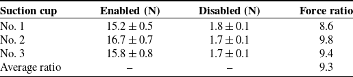
Comparison of adsorption forces with the self-closing function enabled and disabled.

Table II. Long description
The table compares the adsorption forces of three suction cups with the self-closing function enabled and disabled. It has four rows and four columns. The columns are labeled ‘Suction cup’, ‘Enabled (N)’, ‘Disabled (N)’, and ‘Force ratio’. The rows are labeled ‘No. 1’, ‘No. 2’, ‘No. 3’, and ‘Average ratio’. Row 1: No. 1, Enabled (N) 15.2 0.5, Disabled (N) 1.8 0.1, Force ratio 8.6. Row 2: No. 2, Enabled (N) 16.7 0.7, Disabled (N) 1.7 0.1, Force ratio 9.8. Row 3: No. 3, Enabled (N) 15.8 0.8, Disabled (N) 1.7 0.1, Force ratio 9.4. Row 4: Average ratio, Enabled (N) -, Disabled (N) -, Force ratio 9.3.
Values are presented as mean ± standard deviation (n = 5).
The nine suction cups located at the bottom of the gripper were indexed from No. 1 to No. 9, as shown in Figure 4. Owing to the symmetric arrangement of the suction-cup array, suction cups No. 1, No. 2, and No. 3 were selected as representative positions for pull-off force measurement.
Schematic of suction cup layout and numbering.

During each pull-off test, only the suction cup being evaluated was fully sealed by the rigid suction-force testing plate, while the remaining eight suction cups were left uncovered. Therefore, these uncovered suction cups were simultaneously exposed to atmospheric leakage. This configuration represents a demanding multi-cup leakage condition and enables the simultaneous leakage-isolation capability of the SCS array to be evaluated.
To provide a controlled comparison between complete and incomplete leakage isolation, suction cup No. 5 was selected as the control unit. In the self-closing-enabled state, elastic balls were installed in all nine suction cups. The increased airflow through the eight uncovered suction cups drove their respective elastic balls toward the suction orifices, thereby passively closing and isolating these leakage branches. In the self-closing-disabled state, the elastic ball in suction cup No. 5 was removed. Consequently, No. 5 remained continuously open to the atmosphere, whereas the other uncovered suction cups retained their self-closing capability. The two configurations therefore differed only in whether the leakage branch at No. 5 could be passively isolated, allowing the effect of the self-closing mechanism on the suction performance of the sealed test cup to be quantified.
For each test, a rigid suction-force testing plate was positioned over the selected suction cup (No. 1, No. 2, or No. 3) to ensure full sealing contact, while the other eight suction cups remained uncovered. A calibrated digital push-pull force gauge (ALIPO, resolution: 0.1 N) was then used to apply a normal pulling force until complete detachment occurred, as shown in Figure 5. The peak force was recorded.
Measurement process of the adsorption force for suction cup No. 1, 2, and 3.

The actual suction force was calculated as:
 \begin{equation} F_{i}=f_{i}+G_{b} \end{equation}
Where
 $F_{i}$
is the actual adsorption force,
 $f_{i}$
is the force measured by the digital push-pull force gauge, and
 $G_{b}$
is the weight of the suction force detection plate.
Tables II summarize the measured adsorption forces of suction cups No. 1–3 under the self-closing-enabled and self-closing-disabled states, respectively. The same pneumatic pump and tubing configuration were maintained throughout all comparative tests. Statistical analysis showed a significant difference between the two states (p
 $ \lt $
0.001), while the relatively low standard deviations indicate acceptable measurement repeatability.
Under the self-closing-enabled state, the average adsorption forces of suction cups No. 1–3 were 15.2, 16.7, and 15.8 N, respectively. Under the self-closing-disabled state, the corresponding values were 1.8, 1.7, and 1.7 N, respectively. The resulting force ratios were approximately 8.6, 9.8, and 9.4, respectively, yielding an average force ratio of approximately 9.3, as shown in Figure 6.
Adsorption performance of the adaptive vacuum gripper.

These observations indicate the importance of leakage isolation in a shared vacuum network. In the enabled state, although eight suction cups were simultaneously uncovered, their leakage branches were passively isolated by the corresponding SCSs, allowing the sealed test cup to maintain a relatively high adsorption force. In contrast, when only one of these branches (No. 5) was prevented from self-closing, the resulting continuous leakage caused a substantial reduction in the adsorption force of the tested cup. The results therefore confirm that multiple SCS units can operate simultaneously to isolate uncovered suction branches and prevent local leakage from degrading the vacuum performance of the remaining sealed suction cup.
It should be noted that the average force ratio of approximately 9.3 is a leakage-tolerance metric obtained under the specific multi-cup leakage configuration investigated here. It does not represent a universal multiplication of suction force under all operating conditions. Rather, it quantifies the benefit of passive leakage isolation by comparing complete isolation of the uncovered branches with a reference condition in which one branch remains continuously open to the atmosphere.
4.2. Orientation robustness of the SCS
To evaluate the influence of installation orientation on the operating reliability of the SCS, additional experiments were conducted using a single suction-cup unit equipped with the elastic ball. The tested unit had the same geometric parameters as those used in the gripper. A single SCS was used to eliminate the influence of interactions among multiple suction branches.
As shown in Figure 7, the SCS was evaluated under normal, inclined, horizontal, and inverted configurations. For each orientation, the initial state, leakage-isolation state, and object-contacting adsorption state were recorded. Each orientation was tested ten times. After vacuum activation under the uncovered condition, the vacuum pressure stabilized at approximately − 0.096 MPa for all tested orientations, indicating successful isolation of the leakage path. When the suction cup was brought into contact with the object, stable adsorption was achieved, and the vacuum pressure also stabilized at the same vacuum level at all tested orientations. This confirms that changes in installation orientation did not cause unintended blockage of the suction orifice by the elastic ball.
Experimental verification of the orientation adaptability of the SCS. The SCS was tested at different inclination angles (0°, 60°, 90°, 120°, and 180°). (a) Initial vacuum-off states; (b) leakage-isolation states after activating the vacuum source, where the establishment of a stable vacuum pressure indicates successful leakage isolation; (c) object-contacting adsorption states under different orientations, where stable adsorption confirms unobstructed vacuum transmission.

The orientation robustness of the SCS is attributed to the constrained motion of the elastic ball. The lightweight ball, elastic cord, and protruding structure around the suction orifice limit the gravity-induced displacement of the ball and prevent unintended blockage under different installation orientations. Therefore, the closing action is mainly induced by leakage airflow rather than by the installation orientation.
4.3. Grasping demonstrations on objects with different shapes
Further validation experiments were conducted using five representative household objects with different shapes and volumes, including a glass bottle, mobile phone, pill case, computer mouse, and plastic container, as shown in Figure 8.
Adsorption performance of the adaptive vacuum gripper.

Figure 8. Long description
Panel 1: A photo of a glass bottle being held by an adaptive vacuum gripper. The bottle is clear and cylindrical. Panel 2: A photo of a mobile phone being held by an adaptive vacuum gripper. The phone is rectangular and has a screen. Panel 3: A photo of a pill case being held by an adaptive vacuum gripper. The pill case is rectangular and has a label. Panel 4: A photo of a computer mouse being held by an adaptive vacuum gripper. The mouse is curved and has buttons. Panel 5: A photo of a plastic container being held by an adaptive vacuum gripper. The container is rectangular and has a lid.
Each object was tested five times. A flow meter was used to determine the minimum airflow rate at which detachment occurred. The measured results are presented as mean values with standard deviations in Figure 9.
As shown in Figure 9, different subsets of suction cups were activated depending on the object geometry. Nevertheless, the measured minimum detachment flow rates exhibited limited variation among the tested objects. This indicates that the proposed gripper can automatically redistribute effective suction units while maintaining stable grasping performance.
4.4. Comparison with existing leakage-mitigation approaches
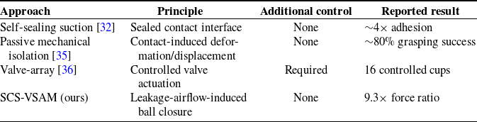
Representative leakage-mitigation approaches are compared in Table III. The self-sealing design in ref. [Reference Song, Drotlef, Son, Koivikko and Sitti32] relies on establishing a sealed contact interface to generate suction, while the passive mechanical mechanism in ref. [Reference Kessens and Desai35] requires contact-induced deformation or displacement to activate leakage prevention. Active valve-array systems such as ref. [Reference Martínez-Peral, Borrell Méndez, Segura Heras and Perez-Vidal36] isolate suction branches through actively controlled valves and external control hardware.
Comparison of representative leakage-mitigation approaches for suction gripping.

Table III. Long description
A table comparing different leakage-mitigation approaches for suction gripping. The table has four rows and four columns. The columns are labeled Approach, Principle, Additional control, and Reported result. Row 1: Self-sealing suction, Sealed contact interface, None, 4 adhesion. Row 2: Passive mechanical isolation, Contact-induced deformation/displacement, None, 80 percent grasping success. Row 3: Valve-array, Controlled valve actuation, Required, 16 controlled cups. Row 4: SCS-VSAM, Leakage-airflow-induced ball closure, None, 9.3 force ratio.
Note: Reported results were obtained under different experimental conditions and are not intended for direct numerical comparison.
Minimum detachment flow rate for different objects. The error bars represent standard deviations calculated from five repeated trials.

In contrast, the proposed SCS is triggered directly by the airflow condition inside the suction cavity. When leakage produces sufficiently high airflow, the resulting aerodynamic force lifts the elastic ball and closes the suction orifice. This activation mechanism does not rely on contact-induced deformation and requires no individual sensors, active valves, or controllers. Under the investigated leakage condition, the SCS-VSAM achieved an average suction-force ratio of approximately 9.3 between the self-closing-enabled and disabled states.
4.5. Operational envelope and limitations
The proposed gripper is primarily intended for objects containing at least one relatively smooth surface capable of forming a sealed suction interface. However, the self-closing mechanism inherently defines an operational envelope with respect to surface roughness and material porosity. If the surface roughness exceeds the deformation capability of the silicone sealing interface, or if the material porosity generates excessive leakage flow, the airflow may exceed the critical triggering threshold Q derived in Section 3. Under such conditions, the internal elastic ball may be lifted to block the orifice even during attempted contact. The current design has been experimentally validated under the tested orientations, while further optimization may be required for more complex dynamic manipulation scenarios.
Although this fail-safe behavior prevents collapse of the overall system vacuum, the affected suction unit becomes temporarily inactive. Therefore, the grasping performance is governed by the balance among seal compliance, local leakage rate, and the triggering threshold of the SCS units.
5. Conclusion
This paper presented an adaptive suction gripper with passive self-closing and leakage-prevention functionality for robust multi-cup vacuum grasping under partial-contact conditions. The proposed design integrates SCS units with an adaptive body structure, enabling localized leakage isolation without sensors, valves, or electronic control.
Comparative experiments were conducted to evaluate the effectiveness of the self-closing mechanism. Under identical vacuum supply conditions, the average suction forces of three representative suction cups increased from 1.8, 1.7, and 1.7 N in the disabled state to 15.2, 16.7, and 15.8 N in the enabled state, corresponding to performance ratios of 8.6×, 9.8×, and 9.4×, respectively. The average improvement was approximately 9.3× under the tested leakage condition. These results confirm that localized leakage can severely degrade the vacuum level of conventional multi-cup systems, whereas the proposed passive mechanism effectively isolates leakage paths and preserves suction performance. Additional grasping experiments on five household objects with different geometries further demonstrated stable attachment and adaptive suction capability under varying contact conditions. The results indicate that the proposed architecture is suitable for objects with relatively smooth and low-porosity contact surfaces.
The present study primarily validates the passive self-closing and leakage-prevention principle. The variable-stiffness body structure was incorporated to enhance geometric adaptability, but its stiffness modulation performance was not quantitatively investigated in this work and will be studied in future research. Future work will also focus on dynamic manipulation tasks, payload characterization, durability evaluation, and optimization for rougher or more porous surfaces. Overall, this work provides a simple, fully passive, and practical solution for leakage-tolerant suction grasping for complex object-handling scenarios.
Supplementary material
The supplementary material for this article can be found at https://doi.org/10.1017/S0263574726104081.
Acknowledgements
During the preparation and revision of this manuscript, the authors used ChatGPT (OpenAI, GPT-5.6, accessed via https://chatgpt.com) for language editing, grammatical refinement, and improvement of the clarity and readability of the English text. The tool was not used for research design, data generation, data analysis, interpretation of experimental results, or formulation of the scientific conclusions. No proprietary data were used to train or modify the AI tool, and no modifications were made to the underlying model. All AI-assisted text was critically reviewed, revised where necessary, and verified by the authors, who take full responsibility for the accuracy, integrity, and scientific content of the manuscript. The tool was last used for these purposes in September 2026. The authors declare no competing interests arising from its use.
Author contributions
H.Y. conceived the research idea, designed the adaptive suction gripper, developed the theoretical model, and performed the analytical derivation of the self-closing suction mechanism. Y.Z. contributed to mechanical design and prototype fabrication. S.S. provided financial support for the project, supervised the research, and contributed to manuscript revision and proofreading. D.Y. assisted with experimental implementation and data collection. All authors discussed the results and approved the final manuscript.
Financial support
This work was supported by the National Natural Science Foundation of China under the Basic Science Center Program for “Space Robot Intelligent Manipulation” (Grant No. T2388101), the National Natural Science Foundation of China (Grant No. 52475032), and Central Government Guides Local Science and Technology Development Fund Projects (Grant No. 246Z2001G).
Competing interests
The authors declare no conflicts of interest exist.
Ethical standard
Not applicable.