



1. Introduction
Since the development of the triple-deck theory by Stewartson & Williams (Reference Stewartson and Williams1969), Neiland (Reference Neiland1969) and Messiter (Reference Messiter1970), many advances have been made in its application to various flow problems, particularly shock-wave–boundary layer interaction in both supersonic and hypersonic regimes (for example, Neiland Reference Neiland1970; Stewartson Reference Stewartson1970; Brown, Stewartson & Williams Reference Brown, Stewartson and Williams1975; Burggraf Reference Burggraf1975; Smith Reference Smith1988a; Brown, Cheng & Lee Reference Brown, Cheng and Lee1990; Smith & Khorrami Reference Smith and Khorrami1991). Notable advances in triple-deck theory include boundary layer transition and Rayleigh-type instability triggered by wall-mounted disturbances of scale smaller than the lower deck (Smith Reference Smith1979; Smith & Bodonyi Reference Smith and Bodonyi1985; Tutty & Cowley Reference Tutty and Cowley1986). Smith (Reference Smith1988a,Reference Smithb) has discussed finite-time boundary layer break-up due to localised nonlinear singularities as well as steady-state singularities induced by large flow reversals. During this period, there have also been some controversial issues such as the existence and possibility of reverse flow singularity in large separated flows as suggested by Smith (Reference Smith1988b) and Smith & Khorrami (Reference Smith and Khorrami1991), which was disputed by Korolev, Gajjar & Ruban (Reference Korolev, Gajjar and Ruban2002). This issue still remains unresolved.
Another problem that has attracted the particular attention of researchers in recent years is the occurrence of wave-packets in the solutions of unsteady triple-deck equations at moderate scale angles in supersonic and hypersonic flows. Such an instability feature was first noted and discussed by Cassel, Ruban & Walker (Reference Cassel, Ruban and Walker1995) and subsequently explored by Fletcher, Ruban & Walker (Reference Fletcher, Ruban and Walker2004), Logue, Gajjar & Ruban (Reference Logue, Gajjar and Ruban2014) and also Exposito, Gai & Neely (Reference Exposito, Gai and Neely2021). Despite these investigations, the precise nature of the breakdown in the solutions of unsteady triple-deck equations, whether they are physical or numerical, still remains unclear. What prompted the present investigation is our somewhat surprising finding that such wave-packets were encountered at fairly small scale angles in supersonic steady-state triple-deck equations when we attempted to reproduce the solutions of steady-state triple-deck equations by Bos & Ruban (Reference Bos and Ruban2000), who show solutions up to scale angle as high as 8 without encountering any wave-packets.
In considering the supersonic flow over a compression corner, Ruban (Reference Ruban1978) and Rizzetta, Burggraf & Jenson (Reference Rizzetta, Burggraf and Jenson1978) solved the unsteady triple-deck equations. Rizzetta et al. (Reference Rizzetta, Burggraf and Jenson1978) showed that the scale angle for incipient separation was  $\alpha _i \approx 1.57$. The range of scale angles considered by Rizzetta et al. (Reference Rizzetta, Burggraf and Jenson1978) was limited to 3.5. The method of Ruban (Reference Ruban1978) would later be used by Cassel et al. (Reference Cassel, Ruban and Walker1995) to obtain solutions for scale angles up to 3.9. For scale angles greater than 3.9, they found that a wave-packet appears at the corner, which grows unbounded for larger scale angles. According to Tutty & Cowley (Reference Tutty and Cowley1986), a Rayleigh physical instability can spontaneously develop in the numerical solution of supersonic triple-deck equations, provided that the following condition is met:
 \begin{equation} \int_0^{\infty} \frac{{{\rm d} y}}{ (u_0 - c)^2} = 0, \end{equation}
where  $u_0$ is the streamwise velocity in the profile of the unperturbed triple-deck solution, and
 $c$ is the complex wave speed of the disturbance. Tutty & Cowley, in their paper, also make the point that to obtain steady solutions, all ‘unsteady’ instabilities are suppressed. Cassel et al. (Reference Cassel, Ruban and Walker1995), using unsteady solutions, showed that both Fjørtoft's and Rayleigh's velocity profile inflection conditions for the appearance of an instability were met. However, these are necessary but not sufficient conditions. Fletcher et al. (Reference Fletcher, Ruban and Walker2004) then considered this instability more rigorously. They found that the flow was convectively unstable in the range
 $3.2 \leq \alpha \leq 3.7$, and absolutely unstable when
 $\alpha \geq 3.7$. The amplitude of the wave-packet was found to remain bounded for
 $\alpha = 3.7$, but to become unbounded for
 $\alpha \geq 4.2$.
This wave-packet has important implications for the triple-deck theory. Once it appears, it distorts the solution and does not permit a clear interpretation of the results for larger scale angles. The wave-packet has also appeared in the solution of hypersonic flow over a cooled wall, as shown by Cassel, Ruban & Walker (Reference Cassel, Ruban and Walker1996). Steady-state solutions to the triple-deck equations have also been used to analyse the flow for large scale angles. Smith & Khorrami (Reference Smith and Khorrami1991) showed steady-state solutions to supersonic triple-deck equations for scale angles up to 6.6. These results were later questioned by Korolev et al. (Reference Korolev, Gajjar and Ruban2002), who argued that the results were not independent of domain height. Using two different numerical methods, they obtained steady-state solutions to the supersonic triple-deck equations for scale angles up to 7.5. Logue et al. (Reference Logue, Gajjar and Ruban2014) also obtained similar solutions using a spectral method and studied the stability of the steady-state solutions to externally imposed disturbances.
The study of Bos & Ruban (Reference Bos and Ruban2000) considered steady-state solutions for supersonic and subsonic flow over a compression corner. With regard to the supersonic case, wherein they show results up to a scale angle of 8, it is important to point out that their results are significantly different, with respect to several features, from those reported by other authors. Our attempt, therefore, to reproduce their results, outlined in this study, shows that a stationary wave-packet appears at the corner discontinuity when solving the triple-deck equations. These results show that wave-packets can appear with steady-state equations in contrast to restrictions as outlined by Tutty & Cowley (Reference Tutty and Cowley1986).
2. Formulation
The problem being considered is supersonic flow past a compression corner, as sketched in figure 1. The figure shows the triple-deck structure with a ramp angle  $\alpha ^*$ which induces separation if its strength is large enough.
Triple-deck structure of a boundary layer facing a compression corner of physical angle  $\alpha ^*$.

The steady-state triple-deck equations to be considered are those of the incompressible lower deck as usual,
 \begin{gather} u \frac{\partial u}{\partial x} + v \frac{\partial u}{\partial y} ={-} \frac{\partial p}{\partial x} + \frac{\partial^2 u}{\partial y ^2}, \end{gather}
 \begin{gather}\frac{\partial u}{\partial x} + \frac{\partial v}{\partial y} = 0, \end{gather}
with boundary conditions
 \begin{gather} u = v= 0, \quad \text{at}\ y =0, \end{gather}
 \begin{gather}u \rightarrow y + A(x,t) + \ldots, \quad \text{as}\ y \rightarrow \infty, \end{gather}
 \begin{gather}u \rightarrow y, \text{as} \ x \rightarrow - \infty, \end{gather}
where  $A(x,t)$ is the displacement thickness of the lower deck. For supersonic flow over an adiabatic wall, the interaction law is
 \begin{equation} p ={-} \frac{\partial A}{\partial x} + \frac{\partial f}{\partial x}. \end{equation}
Variables have been scaled using the triple-deck scalings as outlined by Bos & Ruban (Reference Bos and Ruban2000).
The equations can be expressed in terms of the shear-stress (see Cassel et al. Reference Cassel, Ruban and Walker1995; Bos & Ruban Reference Bos and Ruban2000). Differentiation of (2.1a) with respect to  $y$ leads to
 \begin{equation} u \frac{\partial \tau}{\partial x} + v \frac{\partial \tau}{\partial y} = \frac{\partial^2 \tau}{\partial y ^2}. \end{equation}
The velocities can be recovered from the streamfunction, defined as  $u = \partial \psi / \partial y$,
 $v = - \partial \psi / \partial x$ and
 \begin{equation} \frac{\partial^2 \psi}{\partial y ^2} = \tau. \end{equation}
The boundary conditions are now
 \begin{gather} \psi = \frac{\partial \psi}{\partial y} = 0, \quad \text{at}\ y =0, \end{gather}
 \begin{gather}\tau \rightarrow 1, \text{as}\ \rightarrow \pm \infty, \end{gather}
 \begin{gather}\tau \rightarrow 1, \text{as}\ y \rightarrow \infty. \end{gather}
The displacement thickness in terms of the shear-stress is expressed as
 \begin{equation} A(x,t) = \lim_{y \rightarrow \infty} (u -y) = \lim_{y \rightarrow \infty} \int_0^{y} (\tau - 1) \, {{\rm d} y}, \end{equation}
so that the interaction law is now expressed as
 \begin{equation} \left.\frac{\partial \tau}{\partial y} \right|_{y = 0} ={-} \frac{\partial^2 }{\partial x ^2} \int_0^{\infty} (\tau - 1) \, {{\rm d} y} + \frac{ {\rm d}^2 f }{ {{\rm d}\kern0.7pt x}^2}. \end{equation}
The wall shape function used in this study is the same as those used by Cassel et al. (Reference Cassel, Ruban and Walker1995) and Bos & Ruban (Reference Bos and Ruban2000),
 \begin{equation} f(x) = \frac{1}{2} \alpha \left( x + \sqrt{x^2 + r^2} \right), \end{equation}
where  $r$ is the rounding parameter, taken as
 $0.5$.
3. Numerical methods
3.1. The Bos–Ruban (BR) method
The BR method (Bos & Ruban Reference Bos and Ruban2000) is almost identical to that of Ruban (Reference Ruban1978) and Cassel et al. (Reference Cassel, Ruban and Walker1995), but with the following differences. The time derivative does not exist; the term  $\partial u / \partial x$ of the convective term
 $u \partial u / \partial x$ is solved implicitly and with a first-order upwind method. A first-order approximation of the derivative
 $\partial \tau / \partial y$ is employed as in (2.8). As done by Cassel et al. (Reference Cassel, Ruban and Walker1995), second-order finite-differences are used for the wall-normal derivatives. The domain is divided into
 $i=1, \ldots, I$ in the streamwise direction, and
 $j=1,\ldots,J$ in the wall-normal direction. Denoting the vector of unknowns at streamwise station
 $i$ as
 $\boldsymbol{T}_{i} = (\tau _{i,1}, \ldots, \tau _{i,J})$, the BR method then leads to a tridiagonal system,
 \begin{equation} \boldsymbol{\mathsf{A}}_{i} \boldsymbol{T}_{i-1} + \boldsymbol{\mathsf{B}}_{i}
\boldsymbol{T}_{i} + \boldsymbol{\mathsf{C}}_{i} \boldsymbol{T}_{i+1} = \boldsymbol{\mathsf{D}}_{i} \quad \text{for} \
i=2, \ldots, I-1. \end{equation}
As discussed therein, matrices  $\boldsymbol{\mathsf{A}}_{i}$ and
 $\boldsymbol{\mathsf{C}}_{i}$ contain zero elements except along the main diagonal due to the momentum equation, and along the first row due to the interaction law. Matrix
 $\boldsymbol{\mathsf{B}}_{i}$ has non-zero elements in the three main diagonals and the first row. Vector
 $\boldsymbol{\mathsf{D}}_{i}$ has two non-zero elements; the first is due to the interaction law, the last due to the boundary condition at
 $y \rightarrow \infty$. Once the solution
 $\boldsymbol{T}_{i}$ is known,
 $u_{i,j}$ and
 $v_{i,j}$ are recovered through the streamfunction. Again, as done by Cassel et al. (Reference Cassel, Ruban and Walker1995), the following coordinate transformation is applied
 \begin{equation} \hat{x} = \frac{2}{\rm \pi} \arctan \left( \frac{x}{a} \right), \quad \hat{y} = \frac{2}{\rm \pi} \arctan \left( \frac{y}{b} \right), \end{equation}
which clips the region  $(-\infty, 0) \leq (x,y) \leq (\infty,y_{\infty })$ to a rectangular domain
 $(-1,0) \leq (\hat {x}, \hat {y}) \leq (1,\hat {y}_{\infty })$. The grid is clustured towards points
 $x = 0$,
 $y = 0$, where the refinement is controlled by stretching parameters
 $a$ and
 $b$. The height domain
 $y_{\infty }$ has been chosen as 50 in this study.
3.2. The Logue method
The method of Logue et al. (Reference Logue, Gajjar and Ruban2014) is described in Logue (Reference Logue2008). Here, the equations in primitive variables (2.1) are considered. Second-order finite differences are applied in the streamwise direction. Transformation (3.2a,b) is used in the streamwise direction only. In the wall-normal direction, Chebyshev collocation points are employed, defined as
 \begin{equation} y_j = \frac{y_{\infty}}{2} (z_j + 1) \quad \text{and} \quad z_j ={-} \cos \frac{j {\rm \pi}}{N_y}, \quad j= 0,1, \ldots, N_y, \end{equation}
where  $N_y$ is the number of points in the wall-normal direction. Derivatives in the wall-normal direction are calculated with Chebyshev differentiation matrices. With this arrangement, a Newton linearisation leads to a pentadiagonal system of equations, which is solved at every iteration until convergence. For the small scale angles considered in the present study, the calculations could start from the initial condition
 $u = y$.
4. Results and discussion
4.1. Results free of wave-packets
We note that Bos & Ruban (Reference Bos and Ruban2000) did not specify their stretching factors  $a$ and
 $b$. In this study, scale angles in the range of
 $\alpha = 1.0$–
 $3.0$ were calculated with
 $a = b= 10$ for the BR method and
 $a = 5$ for the Logue method (see Cassel et al. Reference Cassel, Ruban and Walker1995). At scale angles that give a solution free of wave-packets, the calculations converged within a few iterations. Convergence is here defined as the iteration at which the
 $L_2$ norm of the wall shear-stress, normalised by the first value, is lower than
 $5 \times 10^{-4}$.
Figure 2 shows the shear-stress results for scale angle 1.5 with the BR method, and for 3.0 with the Logue method. Three levels of grid refinement were employed with each method, to show that grid independence has been achieved with meshes  $I = 201$,
 $J = 101$ (for the BR method) and
 $N_x = 401$,
 $N_y = 51$ (for the Logue method). Results with the BR method were independent of further mesh refinement in the wall-normal direction. In triple-deck theory, wall-normal gradients are generally assumed to be negligible compared to streamwise gradients, and therefore the solution is more sensitive to grid refinement in the streamwise direction than in the wall-normal direction.
(a) Shear stress for scale angle 1.5 by the BR method with three grids (blue,  $I = 101$, J =
 $51$; red,
 $I = 201$,
 $J = 101$; green,
 $I = 401$,
 $J = 201$). (b) Shear-stress for scale angle
 $3.0$ by the method of Logue with three grids (blue,
 $N_x = 201$,
 $N_y = 31$; red,
 $N_x = 401$,
 $N_y = 51$; green,
 $N_x = 601$,
 $N_y = 101$). Results are identical for all grids, thus only the last (green) colour is visible.

Figure 3 shows the shear stress and pressure distributions over the wall for scale angles 1.0 and 1.5 with the BR method, and up to  $3.0$ with the Logue method. The results compare well with those of Cassel et al. (Reference Cassel, Ruban and Walker1995) and Bos & Ruban (Reference Bos and Ruban2000), which validates the numerical method for low scale angles.
(a) Shear stress and (b) pressure distributions for scale angles  $\alpha = 1.0, \ldots, 3.0$ in 0.5 increments from blue to red. Present calculations with the BR method (continuous lines,
 $I=201$,
 $J = 101$,
 $a = b = 10$) and solutions obtained with the Logue method (discontinuous lines,
 $N_x = 401$,
 $N_y = 51$,
 $a = 5$).

Incipient separation occurs at a scale angle of  $1.82$ with
 $a = b= 10$. This compares well with the 1.9 value of Cassel et al. (Reference Cassel, Ruban and Walker1995), but much higher than the value reported by Rizzetta et al. (Reference Rizzetta, Burggraf and Jenson1978) (
 $\alpha = 1.57$). Bos & Ruban (Reference Bos and Ruban2000) report an incipient separation angle as
 $\alpha = 1.62$. In fact, closer inspection of shear stress distributions in figure 2(a) of their paper appears to show incipient separation to be nearer to
 $\alpha = 2.0$ than
 $\alpha = 1.62$.
4.2. Existence of wave-packets
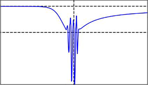
For stretching factors  $a = b = 5$, a stationary wave-packet first appears at the corner with
 $\alpha = 1.82$, as shown in figure 4. With
 $a = b= 10$, it appears at 1.96 (figure 5). The difference is due to the lower resolution of the wave-packet at the corner for
 $a = b= 10$. Once the wave-packet appears, the properties of the wave packet seem identical for both values of grid stretching. The wave-packet stays at the corner, its amplitude bounded. The amplitude grows with the increase in scale angle, however. Two Supplementary Movies available at https://doi.org/10.1017/jfm.2022.955 have been attached to this paper to facilitate the visualisation of the results. Figure 6 shows the shear-stress and pressure distribution for scale angle 3.0 with
 $a = b =10$, showing a large wave-packet located at the corner that we obtained with the BR method. With the Logue method, no wave-packets are seen.
(a) Shear stress and (b) pressure distributions for scale angle  $\alpha = 1.82$, showing a steady wave-packet at the corner. Present calculations with the BR method (blue line,
 $I=201$,
 $J = 101$,
 $a = b = 5$) and solutions obtained with the Logue method (red line,
 $N_x = 401$,
 $N_y = 51$,
 $a = 5$).

(a) Shear stress and (b) pressure distributions for scale angle  $\alpha = 1.96$, showing a steady wave-packet at the corner. Present calculations with the BR method (blue line,
 $I=201$,
 $J = 101$,
 $a = b = 5$) and solutions obtained with the Logue method (red line,
 $N_x = 401$,
 $N_y = 51$,
 $a = 5$).

(a) Shear stress and (b) pressure distributions for scale angle  $\alpha = 3.0$. Present calculations with the BR method (blue line,
 $I=201$,
 $J = 101$,
 $a = b = 10$) and solutions obtained with the Logue method (red line,
 $N_x = 401$,
 $N_y = 51$,
 $a = 5$).

It is possible that wave-packets could potentially represent an alternative solution to the triple-deck equations as a result of bifurcation. In unsteady Navier–Stokes equations and subsonic flow, Nagata (Reference Nagata1990) showed that different solutions can exist besides the well-known pure Couette flow. This seems to be also the case with triple-deck equations. Ruban & Gajjar (Reference Ruban and Gajjar2015) showed a bifurcation diagram for subsonic corner flow. They do not comment on the possibility of bifurcation of triple-deck solutions when discussing supersonic flow at the corner (p. 302). However, such wave-packets must be independent of mesh refinement to represent a true solution to these equations.
The frequency and amplitude of the wave-packet were found to be dependent on grid-refinement. Figure 7 shows the shear-stress at the corner for scale angle 2 and two values of grid refinement,  $I = 201$ and
 $I = 401$. As the number of points in the streamwise direction increases, the frequency and amplitude of the wave-packet increase.
Shear-stress at the corner for scale angle 2 and mesh  $I = 201$,
 $J = 101$ (blue), and mesh
 $I = 401$,
 $J =201$ (red).

To further examine the effect of mesh refinement on the frequency of the wave-packet, we produced the spectrum of the shear-stress for scale angles 2 and 3 and different levels of mesh refinement. This data are shown in figure 8. This figure illustrates the spectrum on  $\hat {x}$ for
 $N$ values in the range of
 $-20 < x < 20$ to focus exclusively on the wave-packet. The values of
 $N$ increase with increasing mesh refinement in the streamwise direction. The absolute value of the resulting Fourier transform is denoted by
 $|F_{ \tau }|$. This parameter is obtained with the BR method for meshes
 $101 \times 51$,
 $201 \times 101$ and
 $301 \times 151$. The spectrum corresponding to the wave-packet free solution, produced with the Logue method, is also included for comparison. For both scale angles 2 and 3, one mode is identified at low wavenumber (
 $k$) values, which corresponds to the wave-packet free solution as indicated by the Logue solution. A second mode appears for higher wavenumbers and BR solutions. This mode is absent in the spectrum corresponding to the Logue solution, and thus must correspond to the wave-packet. It moves towards larger wavenumbers with mesh refinement, the amplitude increasing with increasing number of cells for scale angle 2 and remaining constant for scale angle 3.
Spectrum of the shear-stress for scale angles (a) 2 and (b) 3. Black, Logue method with  $N_x = 401$,
 $N_y = 51$; blue, BS method with
 $I = 101$,
 $J = 51$; red, BR method with
 $I = 201$,
 $J = 101$; green, BR method with
 $I = 301$,
 $J = 151$. Here,
 $N$ is the number of elements within the region
 $x \in [-20,20]$.

These wave-packets therefore do not appear to be the consequence of bifurcation. Moreover, the Rayleigh inflection point theorem, which is a necessary condition for the appearance of instability, is not met for scale angles up to 3.9 as per Cassel et al. (Reference Cassel, Ruban and Walker1995). Since wave-packets have never been observed in other solutions of steady-state triple-deck equations (Smith & Khorrami Reference Smith and Khorrami1991; Korolev et al. Reference Korolev, Gajjar and Ruban2002; Logue et al. Reference Logue, Gajjar and Ruban2014), we believe that such wave-packets are a numerical artefact produced by the algorithm. The possibility of bifurcation raised by Prof. Ruban (private communication) seems characteristic of subsonic triple-deck solutions at the corner, as discussed by Ruban & Gajjar (Reference Ruban and Gajjar2015).
4.3. Further observations
The method of Cassel et al. (Reference Cassel, Ruban and Walker1995) is similar to that of Bos & Ruban (Reference Bos and Ruban2000), and it is therefore possible that the wave-packets shown by Cassel et al. (Reference Cassel, Ruban and Walker1995) and Fletcher et al. (Reference Fletcher, Ruban and Walker2004) are also a product of the numerical scheme employed by these authors. This has been discussed in an earlier study (Exposito et al. Reference Exposito, Gai and Neely2021). Unfortunately, the numerical scheme adopted by Cassel et al. (Reference Cassel, Ruban and Walker1995) and Fletcher et al. (Reference Fletcher, Ruban and Walker2004) is the only method that has been used to produce unsteady solutions to the triple-deck equations. Unsteady solutions obtained with a new numerical scheme would be helpful to determine if wave-packets appear in triple-deck solutions.
Several claims outlined by Bos & Ruban (Reference Bos and Ruban2000) also seem to contradict the existing literature, particularly Logue et al. (Reference Logue, Gajjar and Ruban2014). First, the secondary separation bubble seems significantly smaller for a scale angle of 8. Second, no clear secondary separation is seen in the shear-stress distribution, compared to the results of Smith & Khorrami (Reference Smith and Khorrami1991), Korolev et al. (Reference Korolev, Gajjar and Ruban2002) and Logue et al. (Reference Logue, Gajjar and Ruban2014). Korolev et al. (Reference Korolev, Gajjar and Ruban2002) and Logue et al. (Reference Logue, Gajjar and Ruban2014) reported the highest scale angle was 7.5. Third, the second shear stress minimum of Bos & Ruban (Reference Bos and Ruban2000) moves upstream towards the corner (for scale angles 4 to 8, their figure 2c), unlike the shift downstream of the corner according to Logue et al. (Reference Logue, Gajjar and Ruban2014) (for scale angles 4.5 to 7.5, their figure 1b). Finally, no secondary pressure plateau is seen, in contrast to what is shown in figure 6(b) of Korolev et al. (Reference Korolev, Gajjar and Ruban2002). In our private communication with Prof. Ruban to elicit his response to our results, his comment was that provided our results were mesh independent, then these wave-packets might be some sort of coherent structure. His other comments were that the main focus of their paper was to test their numerical method and also that the ramp geometry was slightly distorted (without specifying how).
To facilitate the reproduction of our results, the MATLAB files with which our results were obtained have been uploaded to a public repository (Exposito Reference Exposito2022).
5. Conclusions
Our attempt at reproducing the data of Bos & Ruban (Reference Bos and Ruban2000) using their numerical methodology has shown significantly different results. Our calculations have shown that a stationary wave-packet appears at the corner in a steady-state solution at a scale angle as low as 1.82 and grows stronger with an increase in scale angle. Such an unexpected feature in a steady-state solution does not seem to have been reported in the triple-deck literature before. We believe this is a numerical artefact specific to their numerical scheme and should be of interest to researchers studying triple-deck theory and numerical interactive problems.
Supplementary movies
Supplementary movies are available at https://doi.org/10.1017/jfm.2022.955.
Acknowledgements
We would like to thank Lt. Col. Dr R. Carr for his continued interest and advice.
Funding
This study is part of the project funded by the Air Force Office of Scientific Research (AFOSR) under grant number FA238619-1-4023.
Declaration of interests
The authors report no conflict of interest.



