1. Introduction
Optimization of the design parameters of mechanisms plays a key role in the development of structures that are appropriate to the operational tasks, allowing for the achievement of the most effective parameters. Often, when developing new mechanisms or machines, parameter optimization is performed only at one stage of the design process, which limits the potential of the device being developed. In the first stage of building an optimized device, its geometric parameters should be optimized. In recent decades, since the second half of the 20th century, global optimization methods have become an important area of research, finding applications in engineering, logistics, nanotechnology, bioinformatics, and mathematical economics. Various optimization methods allow the selection of parameters that meet the requirements of the mechanism and quickly determine, for example, the workspace, safety zones, and link lengths [Reference Gaponenko, Malyshev, Kuzmina and Rybak1–Reference De-An, Jidong, Wei, Ying and Yu3]. The robot’s workspace is the area in which the manipulator can perform its tasks and is determined by the position of the end-effector, whereas the safety zones usually describe the area which the robot links need to cover in order to reach all positions in the workspace, taking into account their dimensions in all positions when performing production or technological functions. Currently, there are many scientific studies that allow for the definition and construction of the safety zones of any robot, but the practical application of these studies is much less common. From the perspective of designing a new mechanism that has not been tested before, information about its safety zones is the key input data, as it determines both the dimensions of the links and the required geometric shape of the external environment for their smooth functioning. Once the geometric parameters of the mechanism are determined, and its working and safety zones meet the initial conditions, the next step is designing the individual elements, where optimization should also be considered. Most methods for designing new products involve building parts based on their minimum and maximum requirements. In modern practice, when additive technologies allow the reproduction of parts in any shape, the approach of topological optimization of material distribution has been actively developed. Topological optimization is a mathematical approach that solves the problem of optimal material distribution within a limited space, satisfying specified parameters, which reduces material consumption, weight, and provides the required rigidity of elements or specified properties [Reference Rybak, Malyshev and Voloshkin4–Reference Shin, Shin and Kang6]. The works of Bendsøe and Kikuchi, starting in 1988, are considered fundamental in the field of topological optimization [Reference Bendsoe and Noboru7]. Their research laid the foundations for modern methods, such as the penalization method for solid isotropic material (SIMP) [Reference Dagkolu, Gokdag and Yilmaz8, Reference Mohamed and Aleksander9], the Level-set method [Reference Sigmund and Maute10, Reference Wang, Wang and Guo11], bidirectional evolutionary structural optimization [Reference Huang and Xie12], and variational topological optimization [Reference Allaire, Jouve and Toader13, Reference Guo, Zhang and Zhong14]. The input data for topological optimization include the forces acting on the mechanism, the method and place of fixation in space, and the safety zones that must be avoided during the formation of the optimization body surface.
Currently, serial-structure manipulators are widely used, with a workspace in the form of a truncated sphere, which does not require the use of complex algorithms for determining the safety zones. However, there are many tasks where manipulators based on parallel-structure mechanisms perform most effectively. The workspace and safety zones of parallel robots involve a curved robotic system surface, as well as inaccessible areas due to the occurrence of special positions. The construction of the safety zone surface for parallel robots is a challenging task, which requires approximating the correct geometric shape. Incorrect design of the body elements or the collaboration of multiple robots can lead to collisions.
One example of the application of topological optimization based on the analysis of the safety zones of a parallel robot is a multi-robotic system (MRS) for aliquoting biomaterial, consisting of two robots with both serial and parallel structures [Reference Rybak, Carbone, Malyshev and Voloshkin15]. Aliquoting is the process of working with an accurately measured portion of a sample (e.g., the volume of a solution), which retains all the properties of the original sample and is used for further analysis.
Below is the main contribution of the work: (The main contributions are listed below):
-
(1) A new layout of a MRS for aliquoting biological material has been proposed, which consists of two robots. The first robot is collaborative and has a serial structure, and the second robot is industrial and has a parallel structure, which allows it to perform the aliquotation process at high speed.
-
(2) A new algorithm for determining the safety zones of robots is presented, as well as a method for constructing three-dimensional models of their obtained safety zones. Based on the constructed safety zones, the choice of their mutual arrangement is made in such a way as to ensure the most efficient use of the workspace.
-
(3) Based on the obtained three-dimensional models of the safety zones and the conducted simulation, the topological optimization of the MRS mounting frame was performed; the simulation results are presented.
The manuscript is organized as follows: Section 2 describes the aliquotation process and the design of the proposed MRS for its implementation; Section 3 presents a mathematical model of robots and an algorithm for constructing safety zones, as well as their three-dimensional models; Section 4 presents an analysis of the relative position of robots based on their safety zones; Section 5 is devoted to the simulation of a parallel robot in a dynamic environment, as a result of which the forces acting on the mounting frame as a result of the robot moving at extreme speeds are determined; Section 6 describes the implementation of topological optimization of the MRS mounting frame using CAD/CAE digital design systems and information about of the safety zones robots and the forces arising from their movements; Section 7 describes the process of building a mounting frame based on the obtained topological optimization body, and also presents a finite element model of the constructed mounting frame and an assessment of its qualitative characteristics; in conclusion, conclusions about the work done are formulated.
2. A robotic system for aliquoting biomaterial
When aliquoting the biological fluid (blood serum) from various patients for further studies, biological material from a test tube with separated fractions (Figure 1a) is distributed into small-volume test tubes (Figure 1b). To do this, the test tube is transferred from the tripod to the work area, where aliquot dosing is carried out (Figure 1c). A schematic description of the process is shown in Figure 2.
Examples of aliquoting.

The scheme of the aliquotation process.

To perform the aliquotation process, a new design of a MRS is proposed, which is shown in Figure 3.
A robotic system for aliquoting biological material.

The MRS includes: building 1, in which a parallel robot of the Deli2 robot is located, moving a dosing device 3 [Reference Rybak, Carbone, Malyshev and Voloshkin15], which performs dosing of biological fluid into equal fractions (aliquots). The replaceable tip 4 on the remote control is secured with an O-ring. The robot 5 of a serial structure with six degrees of freedom is mounted on a fixed base 6 and ensures the movement of tablets 8 using a gripper device within the workspace 7.
From the point of view of designing an MRS, an important task is to determine the relative position of robots, determine the location of their attachment to the base, as well as carrying out topological optimization of this base. To do this, it is necessary to define the safety zones and the workspace of the robots.
3. Description of the method for determining the safety zones of robots
Let us consider a method for constructing robot’s safety zones of serial and parallel structure. In order to avoid collisions of robots in the MRS with each other and with external objects, it is necessary to determine the boundaries of the safety zones of robots, taking into account their geometric parameters and configuration of robots. The block diagram of the Deli robot is shown in Figure 4. To determine the safety zone, a discrete enumeration of the points of the workspace is performed, for each of which an array of coordinates is calculated along the axes of connections with a discrete step. The resulting points corresponding to all possible positions of the end elements are combined into a data set of the safety zone, which can be represented as a three-dimensional model. The input data for the algorithm includes a range of acceptable values for the input and output coordinates of the delta robot. It is important to note that the algorithm does not take into account the design of the robot, which serves as a mount for moving links. A more detailed description of the algorithm is presented in ref. [Reference Rybak, Carbone, Malyshev, Nozdracheva and Dyakonov16] An alternative version of the algorithm for determining the safe space is proposed in ref. [Reference Khalapyan, Rybak, Malyshev, Cherkasov and Vorobyev17].
Block diagram of the Deli robot: (a) general scheme, (b) kinematic chain Ai Bi Ci .

Let’s write down the formulas for determining the coordinates of the Deli robot joint centers (Figure 4) required to determine the position of the links:
 \begin{equation} \boldsymbol{A}_{\textbf{1}}=\left[\begin{array}{c} 0\\ -\frac{a}{2\sqrt{3}}\\[3pt] 0 \end{array}\right], \quad \boldsymbol{A}_{\textbf{2}}=\left[\begin{array}{c} \frac{a}{4}\\[3pt] \frac{a}{4\sqrt{3}}\\[3pt] 0 \end{array}\right], \quad \boldsymbol{A}_{\textbf{3}}=\left[\begin{array}{c} -\frac{a}{4}\\[3pt] \frac{a}{4\sqrt{3}}\\[3pt] 0 \end{array}\right], \end{equation}
 \begin{equation} \boldsymbol{B}_{\textbf{1}}=\left[\begin{array}{c} 0\\[3pt] -\frac{a}{2\sqrt{3}}-d\cos \left(\theta _{1}\right)\\[3pt] -d\sin \left(\theta _{1}\right) \end{array}\right], \quad \boldsymbol{B}_{\textbf{2}}=\left[\begin{array}{c} \frac{\sqrt{3}\cdot \left(\frac{a}{2\sqrt{3}}+d\cos \left(\theta _{2}\right)\right)}{2}\\[3pt] \frac{\frac{a}{2\sqrt{3}}+d\cos \left(\theta _{2}\right)}{2}\\[3pt] -d\sin \left(\theta _{2}\right) \end{array}\right], \quad \boldsymbol{B}_{\textbf{3}}=\left[\begin{array}{c} \frac{-\sqrt{3}\cdot \left(\frac{a}{2\sqrt{3}}+d\cos \left(\theta _{3}\right)\right)}{2}\\[3pt] \frac{\frac{a}{2\sqrt{3}}+d\cos \left(\theta _{3}\right)}{2}\\[3pt] -d\sin \left(\theta _{3}\right) \end{array}\right], \end{equation}
 \begin{equation}\boldsymbol{C}_{\textbf{1}}=\left[\begin{array}{c} x_{p}\\[3pt] y_{p}-\frac{c}{\sqrt{3}}\\[3pt] z_{p} \end{array}\right], \quad \boldsymbol{C}_{\textbf{2}}=\left[\begin{array}{c} x_{p}+\frac{c}{2}\\[3pt] y_{p}+\frac{c}{2\sqrt{3}}\\[3pt] z_{p} \end{array}\right], \quad \boldsymbol{C}_{\textbf{3}}=\left[\begin{array}{c} x_{p}-\frac{c}{2}\\[3pt] y_{p}+\frac{c}{2\sqrt{3}}\\[3pt] z_{p} \end{array}\right],\end{equation}
 \begin{equation} \boldsymbol{B}_{\textbf{11}}=\left[\begin{array}{c} -\frac{h}{2}\\[3pt] -\frac{a}{2\sqrt{3}}-d\cos \left(\theta _{1}\right)\\[3pt] -d\sin \left(\theta _{1}\right) \end{array}\right], \quad \boldsymbol{B}_{\textbf{12}}=\left[\begin{array}{c} \frac{h}{2}\\[3pt] -\frac{a}{2\sqrt{3}}-d\cos \left(\theta _{1}\right)\\[3pt] -d\sin \left(\theta _{1}\right) \end{array}\right], \end{equation}
 \begin{equation} \boldsymbol{B}_{\textbf{21}}=\left[\begin{array}{c} \displaystyle\frac{\sqrt{3}\left(\displaystyle\frac{a}{2\sqrt{3}}+d\cos \left(\theta _{2}\right)\right)}{2}+\displaystyle\frac{h}{4}\\[3pt] \displaystyle\frac{\displaystyle\frac{a}{2\sqrt{3}}+d\cos \left(\theta _{2}\right)}{2}-\displaystyle\frac{\sqrt{3}h}{4}\\[3pt] -d\sin \left(\theta _{2}\right) \end{array}\right], \quad \boldsymbol{B}_{\textbf{22}}=\left[\begin{array}{c} \displaystyle\frac{\sqrt{3}\left(\displaystyle\frac{a}{2\sqrt{3}}+d\cos \left(\theta _{2}\right)\right)}{2}-\frac{h}{4}\\[3pt] \displaystyle\frac{\displaystyle\frac{a}{2\sqrt{3}}+d\cos \left(\theta _{2}\right)}{2}+\frac{\sqrt{3}h}{4}\\[3pt] -d\sin \left(\theta _{2}\right) \end{array}\right], \end{equation}
 \begin{equation} \boldsymbol{B}_{\textbf{31}}=\left[\begin{array}{c} \displaystyle\frac{-\sqrt{3}\left(\displaystyle\frac{a}{2\sqrt{3}}+d\cos \left(\theta _{3}\right)\right)}{2}-\frac{h}{4}\\[3pt] \displaystyle\frac{\displaystyle\frac{a}{2\sqrt{3}}+d\cos \left(\theta _{3}\right)}{2}-\displaystyle\frac{\sqrt{3}h}{4}\\[3pt] -d\sin \left(\theta _{3}\right) \end{array}\right], \quad \boldsymbol{B}_{\textbf{32}}=\left[\begin{array}{c} \displaystyle\frac{-\sqrt{3}\left(\displaystyle\frac{a}{2\sqrt{3}}+d\cos \left(\theta _{3}\right)\right)}{2}+\frac{h}{4}\\[3pt] \displaystyle\frac{\displaystyle\frac{a}{2\sqrt{3}}+d\cos \left(\theta _{3}\right)}{2}+\displaystyle\frac{\sqrt{3}h}{4}\\[3pt] -d\sin \left(\theta _{3}\right) \end{array}\right], \end{equation}
 \begin{equation} \boldsymbol{C}_{\textbf{11}}=\left[\begin{array}{c} x_{p}-\frac{h}{2}\\[3pt] y_{p}-\frac{c}{\sqrt{3}}\\[3pt] z_{p} \end{array}\right], \quad \boldsymbol{C}_{\textbf{12}}=\left[\begin{array}{c} x_{p}+\frac{h}{2}\\[3pt] y_{p}-\frac{c}{\sqrt{3}}\\[3pt] z_{p} \end{array}\right], \end{equation}
 \begin{equation} \boldsymbol{C}_{\textbf{21}}=\left[\begin{array}{c} x_{p}+\frac{c}{2}+\frac{h}{4}\\[3pt] y_{p}+\frac{c}{2\sqrt{3}}-\frac{\sqrt{3}h}{4}\\[3pt] z_{p} \end{array}\right], \quad \boldsymbol{C}_{\textbf{22}}=\left[\begin{array}{c} x_{p}+\frac{c}{2}-\frac{h}{4}\\[3pt] y_{p}+\frac{c}{2\sqrt{3}}+\frac{\sqrt{3}h}{4}\\[3pt] z_{p} \end{array}\right], \end{equation}
 \begin{equation} \boldsymbol{C}_{\textbf{31}}=\left[\begin{array}{c} x_{p}-\frac{c}{2}-\frac{h}{4}\\[3pt] y_{p}+\frac{c}{2\sqrt{3}}-\frac{\sqrt{3}h}{4}\\[3pt] z_{p} \end{array}\right], \quad \boldsymbol{C}_{\textbf{32}}=\left[\begin{array}{c} x_{p}-\frac{c}{2}+\frac{h}{4}\\[3pt] y_{p}+\frac{c}{2\sqrt{3}}+\frac{\sqrt{3}h}{4}\\[3pt] z_{p} \end{array}\right], \end{equation}
The obtained formulas for the coordinates of the centers of the Deli robot joints s depend on the values of the input coordinates (angles
 $\theta _{i}$
of rotation of the drive rotary joints) and the output coordinates (coordinates of the point P of the center of the mobile platform).
Knowing the lengths of the links, we determine the coordinates of the points located on the axis of the links with a discrete step equal to
 $\frac{\delta }{2}$
, where
 $\delta$
– accuracy of approximation. Let’s write down the coordinates of the points
 $D_{j}$
, located on the axis of the link
 $A_{i}B_{i}$
 \begin{equation} \boldsymbol{D}_{\boldsymbol{j}}=\left[\begin{array}{c} x_{Ai}+\displaystyle\frac{j\displaystyle\frac{\delta }{2}\left(x_{Bi}-x_{Ai}\right)}{d}\\[3pt] y_{Ai}+\displaystyle\frac{j\displaystyle\frac{\delta }{2}\left(y_{Bi}-y_{Ai}\right)}{d}\\[3pt] z_{Ai}+\displaystyle\frac{j\displaystyle\frac{\delta }{2}\left(z_{Bi}-z_{Ai}\right)}{d} \end{array}\right] \end{equation}
where
 $j$
is the number of the point on the link
 $A_{i}B_{i}$
,
 $x_{Ai}$
,
 $y_{Ai}$
,
 $z_{Ai}$
,
 $x_{Bi}$
,
 $y_{Bi},\, z_{Bi}$
– coordinates of the joint centers
 $A_{i}$
and
 $B_{i}$
.
The coordinates of points
 $D_{j}$
located on other links are determined similarly. The calculated points
 $D_{j}$
for each of the possible positions of the end-effector are entered into the array of safety zones. Figure 5 shows a part of the safety zones of the Deli robot corresponding to all permissible positions of the A
1
B
1
link. To determine the safety zones of the robot, a technique has been implemented that involves the iterative discrete determination of the coordinates of points
 $D_{j}$
on the axes of all links at all possible positions. For the Deli robot, in addition to the points
 $D_{j}$
on the axes of all links, a set of points defining the movable and fixed platforms is also defined and added to the safety zones.
Part of the safety zones is the work of the Deli corresponding to the A 1 B 1 link.

An algorithm for determining the safety zones using multi-threaded calculations has been developed. The algorithm is shown in Figure 6.
The algorithm for determining the safety zones.

The input data for the algorithm consists of the range of acceptable values for the robot’s input or output coordinates. The intervals are discretely divided. The output of the algorithm is an array of safety zones.
Let’s consider a similar task of forming a safety zone for a UNI robot. Figure 7 shows a block diagram of a robot with a serial UNI structure. The lengths of the links are indicated as
 $L_{i}$
,
 $i\in 0,\ldots ,6$
. The angles of rotation of the joints are indicated as
 $\theta _{i}$
,
 $i\in 1,\ldots ,6$
.
Block diagram of the UNI robot.

Let’s write down the formulas for determining the coordinates of the centers of the joints (D, E, F, G, H), the work of UNI, and the points K and J located on the link FG, required to determine the position of the links. At the same time
 $\sin (\theta _{i})$
let’s denote it as
 $s_{i}$
and
 $\cos (\theta _{i})$
as
 $C_{i}$
.
 \begin{equation}\boldsymbol{D}=\left[\begin{array}{c} 0\\[3pt] 0\\[3pt] L_{0} \end{array}\right] \quad \boldsymbol{E}=\left[\begin{array}{c} L_{1}s_{1}\\[3pt] -L_{1}C_{1}\\[3pt] L_{0} \end{array}\right] \quad \boldsymbol{F}=\left[\begin{array}{c} L_{1}s_{1}+L_{2}C_{1}C_{2}\\[3pt] L_{2}C_{2}s_{1}-L_{1}C_{1}\\[3pt] L_{0}+L_{2}s_{2} \end{array}\right] \quad \boldsymbol{K}=\left[\begin{array}{c} s_{1}(L_{1}-L_{3}^{'})+L_{2}C_{1}C_{2}\\[3pt] L_{2}C_{2}s_{1}-C_{1}(L_{1}-L_{3}^{'})\\[3pt] L_{0}+L_{2}\cdot s_{2} \end{array}\right] \end{equation}
 \begin{equation} \boldsymbol{J}=\left[\begin{array}{c} (L_{1}-L_{3}^{'})s_{1}+L_{2}C_{1}C_{2}+L_{3}C_{1}C_{2}C_{3}-L_{3}^{'}C_{1}s_{2}s_{3}\\[3pt] L_{2}C_{2}s_{1}- (L_{1}-L_{3}^{'})C_{1}+L_{3}^{'}C_{2}C_{3}s_{1}-L_{3}^{'}s_{1}s_{2}s_{3}\\[3pt] L_{0}+L_{2}s_{2}+L_{3}^{'}C_{2}s_{3}+L_{3}^{'}C_{3}s_{2} \end{array}\right] \end{equation}
 \begin{equation}\boldsymbol{G}=\left[\begin{array}{c} (L_{1}-L_{3}^{'}+L_{4})s_{1}+L_{2}c_{1} c_{2}+L_{3}c_{1}c_{2}c_{3}-L_{3}c_{1}s_{2}s_{3}\\[3pt] L_{2}c_{2}s_{1}-(L_{1}-L_{3}^{'}+L_{4})c_{1}+L_{3}c_{2}c_{3}s_{1}-L_{3}s_{1}s_{2}s_{3}\\[3pt] L_{0}+L_{2}s_{2}+L_{3}c_{2}s_{3}+L_{3}c_{3}s_{2} \end{array}\right]\end{equation}
 \begin{equation}\boldsymbol{H}=\left[\begin{array}{c} L_{4}(C_{4}(C_{1}C_{2}s_{3}+C_{1}C_{3}s_{2})- s_{4}(C_{1}s_{2}s_{3}-C_{1}C_{2}C_{3}))+L_{5}s_{1}+L_{2}C_{1}C_{2}+L_{3}C_{1}C_{2}C_{3}-L_{3}C_{1}s_{2}s_{3}\\[3pt] L_{4}(C_{4}(C_{2}s_{1}s_{3}+C_{3}s_{1}s_{2})- s_{4}(s_{1}s_{2}s_{3}-C_{2}C_{3}s_{1}))-L_{5}c_{1}+L_{2}C_{2}s_{1}+L_{3}C_{2}C_{3}s_{1}-L_{3}s_{1}s_{2}s_{3}\\[3pt] L_{0}+L_{2}s_{2}-L_{4}(C_{4}(C_{2}c_{3}-s_{2}s_{3})- s_{4}(c_{2}s_{3}+C_{3}s_{2}))+L_{3}C_{2}s_{3}+L_{3}c_{3}s_{2} \end{array}\right],\end{equation}
 \begin{equation} \boldsymbol{P}=\left[\begin{array}{c} x_{P}\\[3pt] y_{P}\\[3pt] z_{P} \end{array}\right], \end{equation}
where
 \begin{eqnarray*} x_{P} &=& L_{6}\big(C_{5}s_{1}+s_{5}\big(C_{4}(c_{1}s_{2}s_{3}-C_{1}C_{2}C_{3})+s_{4}(c_{1}c_{2}s_{3}+C_{1}C_{3}s_{2})\big)\big)+L_{4}\big(C_{4}(C_{1}C_{2}s_{3}+C_{1}C_{3}s_{2}) \nonumber\\ && -\, s_{4}(C_{1}s_{2}s_{3}-C_{1}C_{2}C_{3})\big)+L_{5}s_{1}+L_{2}C_{1}C_{2}+L_{3}C_{1}C_{2}C_{3}-L_{3}C_{1}s_{2}s_{3} \end{eqnarray*}
 \begin{eqnarray*} y_{P} &=& L_{4} \big(C_{4} (c_{2}s_{1}s_{3}+C_{3}s_{1}s_{2}) -s_{4} (s_{1}s_{2}s_{3}-C_{2}C_{3}s_{1})\big)-L_{6} \big(C_{1}c_{5}-s_{5}\big(C_{4}(s_{1}s_{2}s_{3}-C_{2}C_{3}s_{1}) \nonumber\\ && +\, s_{4}(c_{2}s_{1}s_{3}+C_{3}s_{1}s_{2})\big)\big) - L_{5}c_{1}+L_{2}C_{2}s_{1}+L_{3}C_{2}C_{3}s_{1}-L_{3}s_{1}s_{2}s_{3} \end{eqnarray*}
 \begin{eqnarray*} z_{P} &=& L_{0}+L_{2}s_{2}-L_{4}\big(C_{4}(C_{2}c_{3}-s_{2}s_{3})- s_{4}(c_{2}s_{3}+C_{3}s_{2})\big)+L_{3}C_{2}s_{3}+L_{3}C_{3}s_{2} \nonumber\\ && -\, L_{6}s_{5}(C_{4}(c_{2}s_{3}+C_{3}s_{2}) + s_{4}(c_{2}c_{3}-s_{2}s_{3})) \end{eqnarray*}
The obtained formulas are used in the algorithm for determining the safety zones of the UNI robot, similar to the algorithm for the Deli robot shown in Figure 6.
The simulation of safety zones for the following geometric dimensions of the Deli robot is performed:
 $a=300$
mm,
 $c=d=e=960$
mm,
 $h=100$
mm, and sizes UN3:
 $L_{0}=151.9$
mm,
 $L_{1}=120$
mm,
 $L_{2}=243.65$
mm,
 $L_{3}=213.25$
mm,
 $L_{3}^{'}=93$
mm,
 $L_{4}=112.35$
mm,
 $L_{5}=85.35$
mm,
 $L_{6}=81.9$
mm. The simulation results for the Deli robot are shown in Figure 8, and for UN3 – in Figure 8(b).
The safety zones: (a) the work of the Deli, (b) the UNI robot.

4. Analysis of the relative location of the safety zones
We will analyze the simulation results, which involve checking the relative positions of the manipulators, taking into account the intersection of their safety zones. To solve this problem, we will determine the minimum distance between the safety zones. To do this, the distance Δ between the centers of the parallelepipeds included in the safety zones of the manipulators is iteratively determined. The dimensions of the parallelepipeds for each measurement are equal to the accuracy of the approximation
 $\delta$
. Therefore, the distance from the center of the parallelepiped to its top is
 $\frac{\sqrt{2}\delta}{2}$
for each of the two parallelepipeds. Based on this, the condition for the absence of a possible intersection has the form
 \begin{equation}{\unicode[Arial]{x0394}} \gt r_{link1}+r_{link2}+\sqrt{2}\delta,\end{equation}
where
 $r_{link1},r_{link2}$
– the radii of the manipulator links. If the condition is not met for any of the combinations of parallelepipeds, the iterative check is terminated.
Let’s consider the simulation results for various mutual arrangements of mechanisms. In the first case (Figure 9a), there is no intersection of the links. In the second case (Figure 9b), there are intersections, which clearly confirm the intersection of the safety zones.
The mutual arrangement of the safety zones of robots: (a) no intersections, (b) the presence of intersections.

For the collaborative work of two robots, two conditions must be met: the first is the presence of a common workspace shared by both robots, and the second condition requires the absence of intersections between their safety zones. To fulfill both conditions, it is proposed to add restrictions on the input coordinates of the UN3 manipulator when the Deli robot operates in the area included in the workspace of both mechanisms. These restrictions will prevent the intersection of the safety zones of the Deli robot and the reduced safety zones of the UNI robot within the specified time interval in the common workspace. The results obtained will enable the creation of a condition for the effective operation of both robots in collaboration, preventing collisions between their links, which is a crucial task for the further detailed design of the MRS. The constructed safety zones will be used in the topological optimization of the MRS base.
5. Simulation modeling the work of a Deli in a dynamic environment
To determine the limiting forces acting on the structural elements of the Deli robot, we will conduct simulation modeling of the kinematic and dynamic parameters under the influence of workloads in operating conditions. The 3D simulation model was developed using NX software (Figure 10a). It consists of a fixed base and an end-effector, which are connected by three parallelogram mechanisms linked to three rotary levers. The mass of the metering device is accounted for at the end-effector. The simulation model is parameterized and can be modified depending on the specified geometric parameters. For visual inspection, the working and safety zones have been added to the simulation model (Figure 10b), and they are updated in accordance with the geometric parameters of the Deli robot.
3D mode the work of the Deli in NX: (a) the work of the Deli in its workspace and safety zones, (b) The simulation model of the robot Deli.

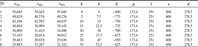
To carry out the simulation, it is necessary to set the required parameters of the robot, as well as the trajectory of the end-effector. To define the trajectory of the Deli robot, the rotation of each drive link must be specified, for which the inverse kinematics problem was solved analytically. The calculation parameters are presented in Table 1. The trajectory is chosen in such a way that it allows for different angles of rotation of the robot’s links.
Kinematic parameters of the Deli robot.

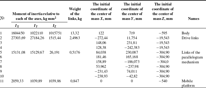
After the movements have been set, we will determine such solution parameters as: simulation time – 0.28 s, the number of simulation steps in the allotted time – 14, acceleration of gravity – 9.8 m/s2 and the direction of its action. Table 2 shows all the main design parameters of the Deli robot required for simulation: the moment of inertia of the links relative to the x, y, z axes, the coordinates of the center of mass, and also the material from which they were made to determine the mass is assigned.
Mass-inertia characteristics of the Deli robot.

Figure 11 shows graphs of forces relative to each of the axes acting on the body during the movement of the Deli robot to the extreme position at the speed of the end-effector 8 m/s2.
Graph of forces acting on the Deli robot body during the movement of the end-effector.

It follows from the graphs that the greatest force acts along the z-axis. The forces acting relative to the x and y axes change direction when the arm passes through the horizontal position during the movement of the end-effector. The magnitude of the forces acting on the body of the Deli robot and the direction of their action are input data for the topological optimization of the MRS base. One of the advantages of using the NX CAD/CAE system is that the peak values of the acting forces can be recorded as variables and used in further modeling.
6. Topological optimization of the MRS mounting frame
Modern CAD/CAE systems allow for the automatic formation of complex part geometries based on data about the fastening method, acting forces, and the area in which the formation of the part’s body is not allowed. To achieve this, the method of topological optimization of material distribution is used. This method is ideal for tasks such as creating a frame in which the work should be placed. When designing the mounting frame, it is essential to consider the robots’ workspace, the forces acting on them, and their mutual positioning. Since all the input data have been successfully determined, we will design the mounting frame for robot installation based on topological material distribution optimization using the NX system.
First, it is necessary to build an Engineering Component Model (ECM) for the topological optimization body, which represents an area of material distribution taking into account the acting forces. The body is created in the NX system. While constructing the body, it is essential to focus on the attachment points of the Deli and UNI robots. The shape of the body itself is not as important; the main objective is to ensure that its dimensions include a small margin, so that during optimization, it does not create unnecessary constraints. The standard “sketch” and “extrude” commands are sufficient to build the body. Afterward, in the same way, we create the model of the mounting frame base, on which the topologically optimized body will be fixed (Figure 12a).
Creating conditions for topological optimization: (a) simplified ECM of the MRS frame; (b) definition of properties in the interface.

The robot safety zones, in stereolithography (STL) format, are added as “Restriction Areas,” within which geometry will not be constructed. In this format, the models consist of hollow surfaces, which are not suitable for use in topological optimization. Using the “Convergent Body” command, a “solid body” is created inside the hollow surface (shell), completely filling it. After creating the ECM for all elements in the NX “Topological Optimization” application, properties are assigned to each of the created models (Figure 12b). Based on these properties, it is determined which body will undergo optimization, which will serve as the base for fixation, and which will be a restriction area in which the optimized body formation should not occur.
Once the properties of all bodies are set, the active forces are assigned relative to the coordinate axes. Based on the simulation of the Deli robot’s motion, the maximum acting forces along the axes are: x = 323 N; y = 675 N; z = 1368 N. Topological optimization is based on the finite element method. The topological optimization body is divided into a finite number of nodes, allowing for the determination of the degree of force action on specific areas of the body. During the first iteration of topological optimization, the size of the edges of the finite elements was 520 mm.
Knowing the maximum load on the mounting frame, a step-by-step removal of the unloaded volume of material inside the topological optimization body is performed (Figure 13a). Figure 13(b) shows the areas of Mises stress limits, represented in color. Blue indicates areas that do not contribute to resisting the applied force, while red highlights the areas of maximum stress within the body. Figure 13(c) shows the ultimate deformation of the body, with red indicating the greatest deformation value.
The results of topological optimization: (a) comparison of the initial and constructed body; (b) Mises stress; (c) deformation of the mounting frame.

The calculation of the presented design requires significant computational power. Initially, a rough calculation with larger finite elements must be performed. As the size of the finite elements decreases, the geometry becomes more detailed, and the mass of the structure is reduced. The mass of the initial and resulting optimized body, shown in Figure 13(a), differs by more than 35 times. After two iterations of optimization, the weight was reduced from 5980 to 168 kg. The second iteration of the topological optimization was performed with a finite element size of 180 mm. While this is still a substantial mass, dark blue areas remain unloaded, as indicated by the model’s color. We will now perform two additional iterations, further decreasing the finite elements, and reduce the mass to 62.2 kg (Figure 14 a, b, c).
The results of the fourth iteration of topological optimization: (a) comparison of the initial and constructed body; (b) Mises stress; (c) ultimate deformation of the mounting frame.

Based on the results of the final fourth iteration of topological optimization, it can be concluded that the resulting frame body is the ultimate. This follows from the fact that further crushing of the finite elements does not give a noticeable decrease in mass, and the difference between the maximum and minimum stresses in the body of the mounting frame is minimal.
The algorithm used has a drawback associated with the fact that the fixing area of the Deli robot body is considered absolutely rigid, as a result of which topological optimization algorithms do not take into account the possibility of turning or twisting the fixing point.
7. Digital design of the mounting frame
The resulting design of the lower platform has a surface that is difficult to manufacture. To solve this problem, we will reverse-engineer the resulting finite element model and construct the structural elements using profile pipes, in accordance with the section of the optimized body material. To do this, we will build a framework of straight lines inside the body of the typologically optimized structure. The points of the frame are located at the nodes of the body where the levers intersect and bends occur (Figure 15a). In this case, the frame is constructed only for one side, after which a mirrored construction is performed to achieve symmetry for the future frame. Once the frame is ready, we execute the “pull along the guide” command, selecting the straight lines of the frame as guides (Figure 15b). When the mounting frame for placing the robots is ready, we assemble the MRS model (Figure 15c).
Creating a mounting frame: (a) a frame made of straight lines; (b) a 3D model of the mounting frame; b – a 3D model of the MRS.

To ensure that the mounting frame meets the strength conditions, we will perform a finite element analysis in NX Nastran (Figure 16a), taking into account the forces applied during topological optimization x = 323 N; y = 675 N; z = 1368 N. The results of the finite element analysis are presented, with Figure 16(b) showing a model with a Mises stress distribution, and Figure 16(c) displaying a deformed model illustrating the displacement of finite elements.
Finite element analysis: (a) Mises stress; (b) displacement (deflection) of the mounting frame.

As a result, the maximum load on the mounting frame was 61.77 MPa. This value for AISI 1005 steel corresponds to a two-fold safety margin. The maximum movement of the mounting frame as a result of the action of forces was 9.408 mm, of which only 0.002 mm as a result of the action of forces arising from the movement of the end-effector. This value of the mounting frame movement is lower than the positioning error of the robot, which is 0.01 mm.
8. Conclusions
A design and mathematical model of two robots in the MRS has been developed to determine the boundaries of the safety zones for each robot, taking into account their configuration and geometric parameters. An algorithm for determining the safety zones using multi-threaded calculations has been synthesized. 3D models of the safety zones were built, and the distance between their centers, equal to 850 mm, was determined, which made it possible to identify the attachment points of the robots. Simulation modeling of the Deli robot’s movements in a dynamic environment was performed, resulting in the determination of the forces acting along the axes: x = 323 N; y = 675 N; z = 1368 N. To prevent collisions between the robots in the MRS and with surrounding structural elements, the frame was constructed using topological optimization methods. After four iterations of topological optimization, a frame body was obtained that ensures the attachment of the robots without causing any intersection with their safety zones. Based on the optimized body of the mounting frame, the construction of a metal structure using standard components was carried out, followed by the assembly of the MRS. Based on the conducted research and the results obtained, a prototype of the MRS will be manufactured in the future. The proposed frame design, after topological optimization, is an example of the practical significance of the proposed algorithm for constructing a safe space.
Acknowledgment
The work was carried out using equipment of High Technology Center at BSTU named after V.G. Shukhov.
Author contribution
Conceptualization, L.R. and G.C.; methodology, L.R and A.V.; software, D.M.; validation, L.R. and V.P.; formal analysis, D.M.; investigation, A.V.; resources, L.R.; data curation, A.V.; writing – original draft preparation, V.C.; writing – review and editing, G.C. and L.R.; visualization, D.M.; supervision, L.R. and G.C.; project administration, G.C.; funding acquisition, L.R. and G.C. All authors have read and agreed to the published version of the manuscript.
Financial support
This work was supported by the state assignment of Ministry of Science and Higher Education of the Russian Federation under Grant FZWN-2020-0017. Using equipment of High Technology Center at BSTU named after V.G. Shukhov.
Competing interests
The authors declare no conflicts of interest exist.
Ethical approval
Not applicable.