I. INTRODUCTION
Besides connectivity, another important factor for modern communication systems is security. Compared with wire-line communication, the security problem is more severe for wireless systems, due to the lack of a physical boundary associated with the broadcasting nature of wireless transmission. This makes confidential information transmitted wirelessly highly vulnerable to interception [Reference Li, Hwu and Ratazzi1].
Conventionally key-based cryptographic technologies are employed at the higher protocol layers, regardless whether the communication systems is wired or wireless, in order to secure data transmission [Reference Mollin2–Reference Forouzan4]. However, these state-of-the-art encryption algorithms, deemed secure enough nowadays, may eventually be compromised due to ever intense computational resource availability. In order to gain the most fundamental level of security, i.e. information theoretical security, [Reference Bloch and Barros5], encryption has to be performed at the physical layer, where the raw interchange between bits of information and modulated signal waveforms takes place.
One way to achieve this is to generate keys at the physical layer by exploiting common randomness at the physical layer, e.g. electromagnetic propagation in a reciprocal multipath environment, instead of using mathematical means. However, this security key establishment method, normally involving five critical procedures of channel probing, signal pre-processing, quantization, information reconciliation, and privacy amplification [Reference Wang, Liu and Vasilakos6], is highly dependent on the characteristics of wireless channels [Reference Chen and Jensen7, Reference Ahmadi and Safavi-Naini8], such as multipath and temporal variation. This makes the key generation approach unsuitable for channel invariant-quasi-static and/or line of sight communication environment. Another less complex approach that can be deployed in any wireless channel scenarios does not involve any keys, i.e. keyless physical layer security [Reference Mukherjee, Fakoorian, Huang and Swindlehurst9]. One promising concept of directional modulation (DM), mainly for free space wireless communication, falls into this category, and is the focus of this review paper [Reference Ding and Fusco10–Reference Daly and Bernhard26].
Generally speaking, DM is a transmitter side technology that is capable of projecting digitally modulated information signals into a pre-specified secure communication spatial direction in free space, while simultaneously distorting the constellation formats of the same signals in all other directions, in such a fashion to lower the possibility of interception [Reference Ding and Fusco11].
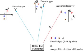
Taking as an example a DM system modulated for quadrature phase-shift keying (QPSK), Fig. 1, the standard formatted QPSK constellation patterns, i.e. central-symmetric square in in-phase and quadrature (IQ) space, are not preserved away from an a-priori defined observation direction θ 0. The fact that the spatial-dependent modulation formats are scrambled along all directions other than θ 0 imposes great challenges on potential eavesdroppers of interception. The DM system models, i.e. the mechanism of constellation pattern distortion, the effectiveness of distortion in terms of security, synthesis approaches, and system demonstrators are discussed in this review paper.
Illustration of the major properties of a quadrature phase-shift keying (QPSK) directional modulation (DM) system. Along a pre-specified direction θ 0 a usable constellation is formed. Away from the desired direction the constellations are scrambled.

The rest of this paper is organized as follows. In Section II, a mathematical description of DM systems is derived and vector representations in IQ space are established for DM analysis [Reference Ding and Fusco10]. With the help of these tools, the necessary conditions for DM arrays are obtained. In Section III, another fundamental aspect, i.e. valid metrics to evaluate the performance of DM systems in a way that is consistent and which allows direct comparison between different DM systems, is discussed and summarized. Sections IV and V are devoted to the DM synthesis methods and the DM physical demonstrators available, respectively. Finally, Section VI concludes the paper and provides some recommendations for potential future development of the DM technology.
II. DM SYSTEM MATHEMATICAL DESCRIPTION AND VECTOR MODEL
The DM definition presented in Section I gives us a working definition on what DM technology is. In this section, a rigorous mathematical description is developed and a vector model is established for DM systems. With these tools, the essence of the DM technology is revealed, and some key concepts are introduced, which form the basis for following sections.
A) Essence of DM technology
Proposition. DM characteristics are enabled by updating beam-forming networks, by either analog or digital means at any stages of transmitters, at the information rate. It was erroneously believed and incorrectly claimed in [Reference Shi and Tennant18–Reference Shi and Tennant31] that the DM properties can only be achieved by applying baseband signals directly onto the radio frequency (RF) frontend or antenna structures.
The above statement is explained as below.
The superimposed radiation from a series of radiating antenna elements in free space, for example the one-dimensional (1D) case, can be formed for N elements, with the summed electric field E at some distant observation point in free space, given as
 $${\bi E} \left(\theta \right) = \displaystyle{{{e^{ - j\mathop {k} \limits^{\rightharpoonup} \cdot \mathop {r} \limits^{\rightharpoonup}}}} \over {\left\vert \mathop {r} \limits^{\rightharpoonup} \right\vert}} \cdot {\left[ {\matrix{ {{\bi AP}_1\left( \theta \right)} \cr {{\bi AP}_2\left( \theta \right)} \cr \vdots \cr {{\bi AP}_{\bi N}\left( \theta \right)} \cr } } \right]^T}\left[ {\matrix{ {{{\bi A}_1} \cdot {e^{\hskip1ptj\mathop {k} \limits^{\rightharpoonup} \cdot {{\mathop {x} \limits^{\rightharpoonup}}_1}}}} \cr {{{\bi A}_2} \cdot {e^{\hskip1ptj\mathop {k} \limits^{\rightharpoonup} \cdot {{\mathop {x} \limits^{\rightharpoonup}}_2}}}} \cr \vdots \cr {{{\bi A}_{\bi N}} \cdot {e^{{j\mathop{k} \limits^{\rightharpoonup}} \cdot {{\mathop {x} \limits^{\rightharpoonup}}_N}}}} \cr } } \right],$$
where
 ${\mathop {k} \limits^{\rightharpoonup}}$
is the wavenumber vector along the spatial transmission direction θ, which ranges from 0° to 180° with boresight at 90°.
 ${\mathop {r} \limits^{\rightharpoonup}}$
and
 ${\mathop {x} \limits^{\rightharpoonup}}_n$
, respectively, represent the location vectors of the receiver and the nth array element relative to the array phase center. “[·]
T
” denotes vector transpose operator.
For isotropic antenna patterns, i.e.
AP
n
(θ) = 1 (n = 1, 2, …, N), and uniform array element spacing
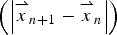 $\left(\left\vert{\mathop {x} \limits^{\rightharpoonup}} _{n + 1} - {\mathop {x} \limits^{\rightharpoonup}} _n \right\vert \right)$
of one half-wavelength, the electric far-field component
E
is solely determined by element excitations (
A
n
), (2)
 $${\bi E}\left( \theta \right) = \sum\limits_{n = 1}^N {\left( {{{\bi A}_n} \cdot {e^{\hskip1ptj\pi \left( {n - {{N + 1} \over 2}} \right) \cos \!\theta}}} \right)}. $$
The term
 $e^{- j{\mathop {k} \limits^{\rightharpoonup}}{\mathop {r} \limits^{\rightharpoonup}}}\,/\,\vert{\mathop {r} \limits^{\rightharpoonup}}\vert$
is dropped, since it is a constant complex scaling factor for the electric field
E
in all directions.
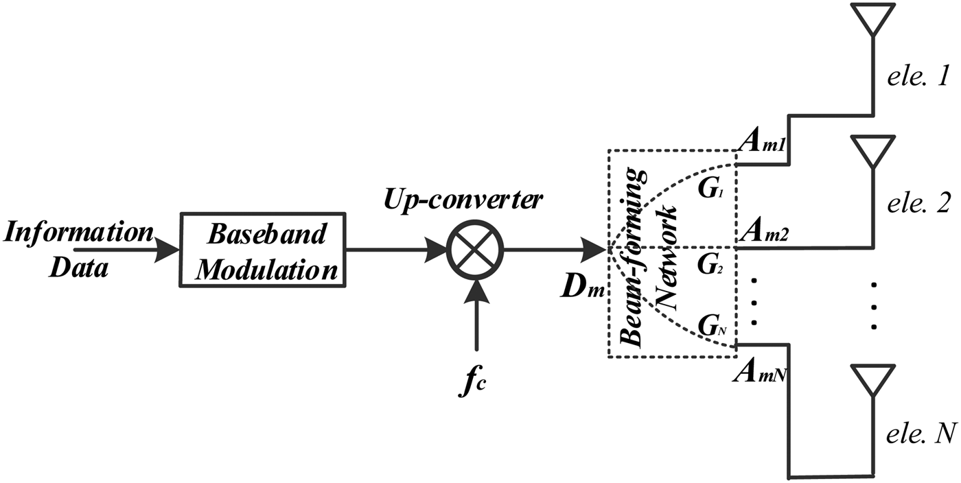
Generally, in a conventional transmitter, here we assume all the antenna elements are actively excited, see Fig. 2, prior to radiation by the antenna array elements, information data are modulated digitally at baseband, up-converted, and then identically distributed to each antenna element via a beam-forming network. Since the beam-forming network is linear and usually is made adaptive at the channel fading rate, its complex gain G n for each n can be regarded as a constant with respect to the modulation rate which is generally much faster than the channel fading rate. Thus, far-field electric field E m is a scaled version (with a complex weights M ) of modulated data D m at each direction, (3), where subscript “m” refers to the mth symbol transmitted. As a consequence the modulation format, namely the constellation patterns in IQ space, is preserved in all spatial directions. Operator “(·)*” denotes complex conjugation:
 $$\eqalign{{{\bi E_m}}\left( \theta \right) & = \sum\limits_{n = 1}^N {\left( {\underbrace {{{\bi D_m}} \cdot {\bi G}_n^{\ast}} _{{{\bi A}_{mn}}} \cdot {e^{\hskip1ptj\pi \left( {n - {{N + 1} \over 2}} \right)\cos\!\theta}}} \right)} \cr & = {\bi D_m} \cdot \underbrace {\sum\limits_{n = 1}^N {\left( {{\bi G}_n^{\ast} \cdot {e^{\hskip1ptj\pi \left( {n - {{N + 1} \over 2}} \right)\cos\!\theta}}} \right)}} _{\bi M}.} $$
For DM systems, in order to achieve direction-dependent signal formats transmission, another degree of freedom has to be introduced. This is achieved by varying G n , and hence M in (3), at the modulation rate during data transmission in order to release the direct dependence of E m on D m , in other words to distort constellation patterns along unsecured spatial directions. The updated G n and M are denoted as G mn and M m , respectively. In a DM transmitter, G mn is updated at the modulation rate as is D m :
 $${\bi E_m}\left( \theta \right) = 1 \cdot \sum\limits_{n = 1}^N {\left( {\left({{{\bi D}_m}{\bi G}_{mn}^{\ast}} \right) \cdot {e^{\hskip1ptj\pi \left( {n - {{N + 1} \over 2}} \right)\cos\!\theta}}} \right)}, $$
 $${\bi E_m}\left( \theta \right) = \left[ {\matrix{ {{\bi D}_m{\bi G}_{m1}^{\ast}} \cr {{{\bi D}_m}{\bi G}_{m2}^{\ast}} \cr \vdots \cr {{{\bi D}_m}{\bi G}_{mN}^{\ast}} \cr}} \right] \cdot \left[ {\matrix{ {1 \cdot {e^{\hskip1ptj\pi \left( {1 - {{N + 1} \over 2}} \right)\cos\!\theta}}} \cr {1 \cdot {e^{\hskip1ptj\pi \left( {2 - {{N + 1} \over 2}} \right)\cos\!\theta}}} \cr \vdots \cr {1 \cdot {e^{\hskip1ptj\pi \left( {N - {{N + 1} \over 2}} \right)\cos\!\theta}}} \cr}} \right].$$
By re-writing (3) as (4) and (5) for DM case, two interpretations can be drawn. The first, from a microwave engineering perspective, (4),
 $\left({{\bi D_m} \cdot {\bi G}_{mn}^{\ast}} \right)^{\ast}$
can be considered as the complex gain,
G
′
mn
, of a baseband information data controlled beam-forming network, into which an RF carrier f
c
, instead of the modulated data stream
D
m
, is injected (Fig. 3). This analog DM architecture in Fig. 3 is actually the DM structures developed or used in [Reference Ding and Fusco13, Reference Shi and Tennant18, Reference Shi and Tennant19, Reference Shi and Tennant23–Reference Daly and Bernhard26, Reference Daly, Daly and Bernhard28, Reference Shi and Tennant30–Reference Shi and Tennant32]. Alternatively, from a signal processing aspect, (5),
 ${\bi D_m} \cdot {\bi G}_{mn}^{\ast}$
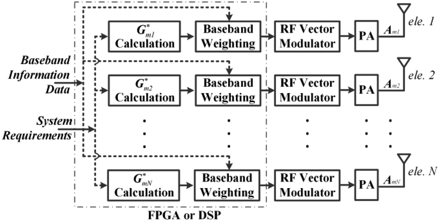
can be regarded as uniquely weighted mth data fed into the nth array element. This weighting is readily implemented at baseband prior to up-conversion if the digital DM architecture presented here as Fig. 4 were to be used.
Conventional “non-DM” transmitter array architecture [Reference Ding and Fusco10].

Generic analog active DM transmitter architecture [Reference Ding and Fusco10].

Generic digital DM transmitter architecture [Reference Ding and Fusco10].

B) Vector representations for DM arrays
Since there are several different ways to implement a DM system as discussed in Section II.A, we require a description technique which is architecture independent and which lends itself to both analysis and synthesis of any class of DM structures. In this section, we analyze the requirements that array excitations A mn need to satisfy for a DM transmitter, regardless of the means of generating A mn .
The two key properties of a DM transmitter which we wish to establish are:
-
• preservation of the transmitted signal format (standard constellation pattern in IQ space) along a pre-specified secure communication direction θ 0 and
-
• distortion of constellation patterns along all other unsecured communication directions.
From a signal processing perspective, E in (2) can be regarded as a detected constellation point in IQ space at receiver sides, denoted as C m for the mth symbol transmitted, (6)
 $${\bi C}_m\left( \theta \right) = \sum\limits_{n = 1}^N {\underbrace {\left( {{\bi A}_{mn} \cdot {e^{\hskip1ptj\pi \left( {n - {{N + 1} \over 2}} \right)\cos\!\theta}}} \right)}_{{\bi B}_{mn}\left( \theta \right)}}. $$
For each symbol transmitted, the vector summation of B mn has to yield the standard constellation point C m_st in IQ space along, and only along, the direction θ 0, which, in mathematical description, is expressed in (7):
 $$\sum\limits_{n = 1}^N {{\bi B}_{mn}\left( {{\theta _0}} \right)} = {\bi C}_{m\_st}\left( {{\theta _0}} \right).$$
From (6), by scanning the observation angle θ, the constellation track in IQ space, C m (θ), of the mth symbol can be obtained. General properties of constellation tracks can be observed from (6), and are summarized as below:
-
(1) For an array with odd number elements, constellation tracks are closed loci, in some extreme cases, these loci collapse to line segments, starting point (θ = 0°) always overlaps with end point (θ = 180°). For the case of even number elements, C m (0°) = − C m (180°). When the array element spacing is changed, the start and end angle will change accordingly.
-
(2) Changing the desired communication direction θ 0 does not affect the shape of the constellation track pattern, it determines only where the tracks start (θ = 0°) and end (θ = 180°).
-
(3) Different vector paths (trajectories of the vector summation,
 $\sum\nolimits_{n = 1}^N {{{\bi B}_{mn}}\left( {{\theta _0}} \right)} $
) inevitably lead to different constellation tracks. This is guaranteed by the orthogonality property of ejnπ
cosθ
for different n within the spatial range 0°–180°.
-
(4) For the qth symbol transmitted, if B qn (θ 0) are the scaled B mn (θ 0) with the same scaling factor K for each n, the constellation track C q (θ) is also the scaled C m (θ) with the scaling factor K .
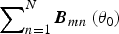
Properties (3) and (4) mean that constellation distortion at other directions can be guaranteed if vectors [ B q1 (θ 0) B q2 (θ 0) ••• B qN (θ 0)] and [ B m1 (θ 0) B m2 (θ 0) ••• B mN (θ 0)] are linearly independent, see (8). Here the qth and the mth symbols in the data stream are different modulated symbols:
 $$\eqalign{ & \left[{\matrix{ {{\bi B}_{q1}\left( {{\theta _0}} \right)} & {{\bi B}_{q2}\left( {{\theta _0}} \right)} & \cdots & {{\bi B}_{qN}\left( {{\theta _0}} \right)} \cr}} \right] \ne \cr & \quad {\bi K} \cdot \left[ {\matrix{ {{\bi B}_{m1}\left( {{\theta _0}} \right)} & {{\bi B}_{m2}\left( {{\theta _0}} \right)} & \cdots & {{\bi B}_{mN}\left( {{\theta _0}} \right)} \cr}} \right].} $$
The combination of (7) and (8) forms the necessary conditions for DM transmitter arrays. Thus, the requirement for the DM array excitations A mn can then be obtained by (6).
With the DM vector model described above the static and dynamic DM transmitters are defined below. This classification facilitates the discussions of DM assessment metrics and DM synthesis approaches that will be presented in Sections III and IV, respectively.
Definition. If along the DM secure communication direction the vector path in IQ space reaching each unique constellation point is independent and fixed, which results in a distorted, but static with respect to time, constellation pattern along other spatial directions, the transmitters are termed “static DM”; on the contrary if the vector paths were randomly re-selected, on a per transmitted symbol basis in order to achieve the same constellation symbol in the desired direction, then the symbol transmitted at the different time slots in the data stream along spatial directions other than the prescribed direction would be scrambled dynamically and randomly. This we call the “dynamic DM” strategy.
With the definition above most of the DM transmitters reported in the open literature, e.g. [Reference Ding and Fusco13, Reference Ding and Fusco14, Reference Shi and Tennant18–Reference Hong, Song and Liu33], fall into the static DM category, while the DM systems reported in [Reference Zhang, Ding and Fusco17, Reference Valliappan, Lozano and Heath34–Reference Hong, Song and Liu37], involving time as another viable to update system settings, can be labeled as dynamic.
III. METRICS FOR ASSESSING PERFORMANCE OF DM SYSTEMS
To gain better cohesion with regard to DM system assessment comparability, this section summarises all the available DM performance metrics.
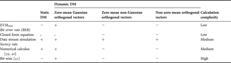
In some previous DM work, e.g. [Reference Chang, Babakhani and Hajimiri22, Reference Shi and Tennant30–Reference Shi and Tennant32], the authors described DM properties that were obtained by certain physical arrangements or synthesis methods; however, no performance assessments were made. In [Reference Shi and Tennant18–Reference Babakhani, Rutledge and Hajimiri21, Reference Shi and Tennant23–Reference Shi and Tennant25], normalized error rate was adopted, but no magnitude and phase reference of detected constellation patterns were defined. Furthermore since channel noise and coding strategy was not considered, this metric is not able to capture differences in performance if (a) a constellation symbol is constrained within its optimal compartment for decoding, e.g. one quadrant for QPSK, but locates at different positions within that compartment and (b) a constellation symbol is out of its compartment but falls into a different compartment. These omissions make the “error rate” of a DM system difficult to use for systematic assessment. In [Reference Zhang, Ding and Fusco17], an error-vector-magnitude-like (EVM-like) figure of merit, FOM DM , for describing the capability of constellation pattern distortion in a DM system was defined. However, it suffers the same problem of no channel noise and coding strategy consideration. It is also found that its computation can yield different values for static and dynamic DM systems due to different reference constellation patterns. In [Reference Hong, Song and Liu33], bit error rate (BER) was used to assess the performance of a QPSK DM system, but no information about how it is calculated was provided. While in [Reference Daly and Bernhard26–Reference Daly29] a closed-form QPSK BER lower bound equation for static DM system evaluation was proposed, which was corrected and further extended in [Reference Ding and Fusco13].
In [Reference Ding and Fusco12], the metrics for assessing the performance of DM systems were formally discussed. It was shown that for static DM systems BER, calculated from either closed-form equations or transmitting random data streams, and secrecy rate [Reference Csiszar and Korner38], normally used in information theory community, were applicable for system performance evaluation, whereas EVM-like metrics, although the channel noise and coding strategy were considered, did not perform well. For dynamic DM systems under the scenarios of zero-mean Gaussian distributed orthogonal interference, EVM-like metrics, BER, and secrecy rate were equivalent and can be converted into each other. For other interference distributions, no closed-form BER and secrecy rate equations were available. Here, the concept of orthogonal interference or vector can be found in [Reference Ding and Fusco11] and will also be presented in Section IV.A.
In order to provide readers a clear picture on metrics for assessing performance of DM systems, all the findings presented in [Reference Ding and Fusco12] are summarized in Table 1.
Summaries of metrics for directional modulation (DM) system performance assessment.

“+”, Metric works; “•”, metric works for quadrature phase-shift keying (QPSK), but not for higher order modulations; “−”, metric cannot be calculated or does not work.
IV. SYNTHESIS APPROACHES FOR DM TRANSMITTER ARRAYS
Prior to the recent efforts in [Reference Ding and Fusco11, Reference Ding and Fusco14–Reference Daly and Bernhard16], the previous DM synthesis attempts were closely bounded up with the physical DM transmitter structures. For passive DM transmitter arrays [Reference Babakhani, Rutledge and Hajimiri20–Reference Chang, Babakhani and Hajimiri22], termed by authors near-field direct antenna modulation, which rely on the complex transformation between near-field electromagnetic boundaries and far-field behaviors, there is no analytical means to map transmitter settings to vector paths in IQ space, and ultimately to the constellation tracks and secrecy performance. As a consequence, it seems nearly impossible for a mathematically rigorous passive DM transmitter, satisfying (7) and (8) in Section II, to be synthesized. Thus, it is natural that no effective synthesis methods other than trial and error can be effected, although the search area can be shrunk using optimization as in [Reference Lavaei, Babakhani, Hajimiri and Doyle42].
On the contrary, in terms of the active DM arrays [Reference Daly and Bernhard26–Reference Daly29], due to the independent excitation of each array element, we can readily transform array excitations and array physical arrangements into vector paths in IQ space in an analytical fashion. Thus, a fit-for-purpose cost function can be established for DM system optimization. Normally, the cost functions link the BER spatial distributions to the array settings. By minimizing the values of the cost functions through population-based optimization algorithms, DM transmitter arrays can be synthesized. However, it should be noted that the decoding functionality of the receiver has a major influence on the quality of recovered data and should be well defined during the BER-driven synthesis [Reference Ding and Fusco13].
While investigating the DM architectures in [Reference Valliappan, Lozano and Heath34–Reference Hong, Song and Liu37], it was realized that, unlike the DM systems described in [Reference Babakhani, Rutledge and Hajimiri20–Reference Chang, Babakhani and Hajimiri22, Reference Daly and Bernhard26–Reference Daly29], under their prescribed working mechanisms no synthesis is required, since in these systems the DM requirements of (7) and (8) are automatically satisfied. This, with the help of the orthogonal vector concept [Reference Ding and Fusco11], indicates that injected interference constantly stays orthogonal to conjugated channel vectors along the intended communication directions. Similarly, the Fourier lens enabled DM transmitters, which were recently proposed in [Reference Zhang, Ding and Fusco17], fall into the same category.
In order to generalize the DM synthesis approaches, based on the actively excited 1D transmitter arrays, we should focus on seeking appropriate array excitations, which enable DM characteristics and improve secrecy performance, irrespective of the means of generating those excitations. With the obtained excitations, the DM transmitters can be constructed by using either analog, e.g. see Fig. 3, or digital means, e.g. see Fig. 4, or alternatively employing suitably featured beam-forming networks.
In Section IV.A, a smart concept, i.e. orthogonal vector, is introduced, and is utilized for DM transmitter array synthesis [Reference Ding and Fusco11]. This approach is compatible for both static and dynamic DM transmitters. In order to meet some other DM system requirements, e.g. detected BER spatial distributions [Reference Ding and Fusco13], far-field radiation patterns [Reference Ding and Fusco14, Reference Ding and Fusco15], and orthogonal interference distributions [Reference Ding and Fusco16], three more synthesis approaches are briefly described in Sections IV.B. These approaches can be regarded as seeking a subset of orthogonal vectors under certain system constraints.
A) Orthogonal vector approach for DM array synthesis
In Section II.B, it is showed that when the same constellation symbol detected along the desired communication direction is reached via different vector paths in IQ space, the resulting constellation tracks are altered accordingly. This leads to the constellation pattern distortion along spatial directions other than the prescribed direction, which is the key property of DM systems. In other words, it is the difference vector between each two vector paths selected to achieve a same standard constellation point in IQ space that enables the DM characteristics. This difference vector is defined as the orthogonal vector, since it is always orthogonal to the conjugated channel vector along the intended spatial direction.
A 1D 5-element array with half-wavelength spacing is taken as an example below to explain the orthogonal vector concept. It is assumed that each antenna element has an identical isotropic far-field radiation pattern.
The channel vector for this system along the desired communication direction θ 0 in free space is
 $$\eqalign{{\mathop {\bi H} \limits^{\rightharpoonup}} \left( {{\theta _0}} \right) & = \left[ {\underbrace {{e^{\hskip1ptj2\pi \cos \!{\theta _0}}}}_{{{\bi H}_1}}} \right. \quad \underbrace {{e^{\hskip1ptj\pi \cos \!{\theta _0}}}}_{{{\bi H}_2}}\quad \underbrace {{e^{\hskip1ptj0}}}_{{{\bi H}_3}} \cr & \quad {\left. {\quad \underbrace {{e^{ - j\pi \cos \!{\theta _0}}}}_{{{\bi H}_4}}\quad \underbrace {{e^{ - j2\pi \cos \!{\theta _0}}}}_{{{\bi H}_5}}} \right]^T}.} $$
If the excitation signal vectors at the array input, [ A m1 A m2 … A m5] T , for the same symbol transmitted at the uth and vth time slots are chosen to be
 $$\eqalign{& {{\mathop {\bi S} \limits^{\rightharpoonup}} _u} = \left[ {\underbrace {{e^{\hskip1ptj\left( { - {\pi \over 4} + 2\pi \cos{\!\theta _0}} \right)}}}_{{{\bi S}_{u1}}}} \right.\quad \underbrace {{e^{\hskip1ptj\left( {{\pi \over 4} + \pi \cos{\!\theta _0}} \right)}}}_{{{\bi S}_{u2}}} \cr & \quad \quad {\left. {\quad \underbrace {{e^{\hskip1ptj\left( {{\pi \over 4}} \right)}}}_{{{\bi S}_{u3}}}\quad \underbrace {{e^{\hskip1ptj\left( {{\pi \over 4} - \pi \cos{\!\theta _0}} \right)}}}_{{{\bi S}_{u4}}}\quad \underbrace {{e^{\hskip1ptj\left( {{{3\pi} \over 4} - 2\pi \cos{\!\theta _0}} \right)}}}_{{{\bi S}_{u5}}}} \right]^T}} $$
and
 $$\eqalign{& {{\mathop {\bi S} \limits^{\rightharpoonup}}_v} = \left[ {\underbrace {{e^{j\left( {{\pi \over 4} + 2\pi \cos{\!\theta _0}} \right)}}}_{{{\bi S}_{v1}}}} \right. \quad \underbrace {{e^{j\left( {{\pi \over 4} + \pi \cos{\!\theta _0}} \right)}}}_{{{\bi S}_{v2}}} \cr & \quad {\left. {\quad \underbrace {{e^{j\left( { - {\pi \over 4}} \right)}}}_{{{\bi S}_{v3}}} \quad \underbrace {{e^{j\left( {{{3\pi} \over 4} - \pi \cos{\!\theta _0}} \right)}}}_{{{\bi S}_{v4}}} \quad \underbrace {{e^{j\left( {{\pi \over 4} - 2\pi \cos \!{\theta _0}} \right)}}}_{{{\bi S}_{v5}}}} \right]^T}.} $$
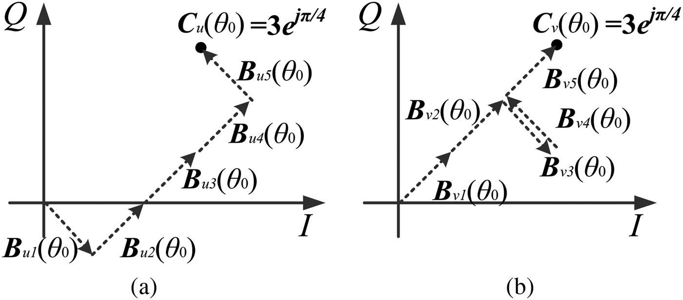
The received vector paths in IQ space along this spatial direction θ 0 are
 $$\eqalign{\mathop{\mathop{{\bi B}} \limits^{\rightharpoonup}}\nolimits_u = \mathop{{\mathop{{\bi H}} \limits^{\rightharpoonup}}} \nolimits^{\ast} \left( {\theta _0} \right) \circ \;\mathop{\mathop{{\bi S}} \limits^{\rightharpoonup}}\nolimits _u & = \left[ \underbrace {{\bi H}_1^{\ast} \cdot {\bi S}_{u1}}_{{\bi B}_{u1}} \quad \underbrace {{\bi H}_2^{\ast} \cdot {\bi S}_{u2}}_{{\bi B}_{u2}} \right. \cr & \quad \left. \quad \underbrace {{\bi H}_3^{\ast} \cdot {\bi S}_{u3}}_{{\bi B}_{u3}}\quad \underbrace {{\bi H}_4^{\ast} \cdot {\bi S}_{u4}}_{{\bi B}_{u4}}\quad \underbrace {{\bi H}_5^{\ast} \cdot {\bi S}_{u5}}_{{\bi B}_{u5}} \right]^T \cr & = \left[ \matrix{ e^{ - j{\pi \over 4}} & {e}^{j{\pi \over 4}} &{e}^{j{\pi \over 4}} &{e}^{j{\pi \over 4}} &{e}^{j{3\pi \over 4}}} \right]^T} $$
and
 $$\eqalign{\mathop{\mathop{{\bi B}} \limits^{\rightharpoonup}}\nolimits _v = \mathop{\mathop{ {\bi H}} \limits^{\rightharpoonup}} \nolimits^{\ast} \left({\theta _0} \right) \circ \mathop{\mathop{{\bi S}} \limits^{\rightharpoonup}} \nolimits_{v} & = \left[\underbrace {{\bi H}_1^{\ast} \cdot {\bi S}_{v1}}_{{\bi B}_{v1}} \quad \underbrace {{\bi H}_2^{\ast} \cdot {\bi S}_{v2}}_{{\bi B}_{v2}} \right. \cr & \quad \left. \quad \underbrace {{\bi H}_3^{\ast} \cdot {\bi S}_{v3}}_{{\bi B}_{v3}} \quad \underbrace {{\bi H}_4^{\ast} \cdot {\bi S}_{v4}}_{{\bi B}_{v4}} \quad \underbrace {{\bi H}_5^{\ast} \cdot {\bi S}_{v5}}_{{\bi B}_{v5}} \right]^T \cr & = \left[ \matrix{ {e}^{j{\pi \over 4}} & {e}^{j{\pi \over 4}} & {e}^{ - j{\pi \over 4}} & {e}^{j{3\pi\over 4}} & e^{j{\pi \over 4}} } \right]^T.} $$
These are shown in Figs 5(a) and 5(b), respectively. Operator “°” denotes Hadamard product of two vectors.
Illustration example of two vector paths derived from two different excitation settings.

The vector summations in
B
un
, and
B
vn
(n = 1, 2, 3, 4, 5) can be calculated as
 $\mathop {{\bi H}} \limits^{\rightharpoonup}{\dag} \left({\theta _0} \right){\mathop {\bi S} \limits^{\rightharpoonup}} _u$
and
 ${\mathop {\bi H} \limits^{\rightharpoonup}}{\dag} \left({\theta _0} \right){\mathop {\bi S} \limits^{\rightharpoonup}} _v$
, both reaching position 3·ejπ
/4 in IQ space. “(·)†” denotes complex conjugate transpose (Hermitian) operator.
The difference between these two excitation signal vectors is
 $$\eqalign{& \Delta{\mathop {\bi S} \limits^{\rightharpoonup}} = {\mathop {\bi S} \limits^{\rightharpoonup}} _v - {\mathop {\bi S} \limits^{\rightharpoonup}} _u = \cr & \quad \quad \sqrt 2 {\left[ {\matrix{ {{e^{j\left({{\pi \over 2} + 2\pi \cos \!{\theta _0}} \right)}}} \hfill & 0 \hfill & {{e^{ - j{\pi \over 2}}}} \hfill & {{e^{j\pi \left( {1 - \cos \!{\theta _0}} \right)}}} \hfill & {{e^{ - j2\pi \cos \!{\theta _0}}}} \hfill \cr}} \right]^T}} $$
which is orthogonal to the conjugated channel vector
 ${\mathop {\bi H} \limits^{\rightharpoonup}}{\ast} \left({\theta _0} \right)$
since
 ${\mathop {\bi H} \limits^{\rightharpoonup}}{\ast} \left({\theta _0} \right) \cdot \Delta{\mathop {\bi S} \limits^{\rightharpoonup}} = 0$
. This
 $\Delta{\mathop {\bi S} \limits^{\rightharpoonup}}$
is the orthogonal vector defined in this section.
With the help of the orthogonal vector concept, a generalized DM synthesis approach was developed in [Reference Ding and Fusco11]. The synthesized DM transmitter array excitation vector
 ${\mathop {\bi S} \limits^{\rightharpoonup}}_{ov}$
takes the form
 $${\mathop {\bi S} \limits^{\rightharpoonup}} _{ov} = {\mathop {\bi \Lambda} \limits^{\rightharpoonup}} + {\mathop {\bi W} \limits^{\rightharpoonup}} _{ov},$$
 ${\mathop {\bi \Lambda} \limits^{\rightharpoonup}}$
is a vector with each entry of array excitations before injecting the orthogonal vector
 ${\mathop {\bi W} \limits^{\rightharpoonup}}_{ov}$
, which is orthogonal to the conjugated channel vector,
 ${\mathop {\bi H} \limits^{\rightharpoonup}}_{ov}^{\ast}$
. Denote
 ${\mathop {\bi Q} \limits^{\rightharpoonup}}_{p}$
(p = 1, 2, …, N−1) to be the orthonormal basis in the null space of
 ${\mathop {\bi H} \limits^{\rightharpoonup}}^{\ast}$
, then
 ${\mathop {\bi W} \limits^{\rightharpoonup}}_{ov} = 1/(N - 1) \cdot \sum\nolimits_{p = 1}^{N - 1} {\left({\mathop {\bi Q} \limits^{\rightharpoonup}} _p \cdot {v_p} \right)} $
. Here,
 ${\mathop {\bi \Lambda} \limits^{\rightharpoonup}}$
is defined as excitations of non-DM beam steering arrays. This excitation contains the information symbol
X
to be transmitted, e.g. ejπ
/4 corresponds to the QPSK symbol “11”.
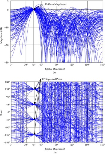
Take a transmitter array consisting of 1D 5-element half-wavelength spaced antenna elements with isotropic radiation patterns, modulated for QPSK for 45° secure communication as an example, Fig. 6 shows simulated far-field patterns in the synthesized dynamic DM system for 100 random QPSK symbols transmitted when the v p are circularly symmetric independent and identically distributed complex Gaussian distributed variables with variance σ v 2 of 0.8. From a receivers’ point of view, the far-field radiation patterns can be interpreted as detected constellation patterns in IQ space along each direction. Thus, it can be concluded that a standard QPSK constellation pattern, i.e. uniform magnitudes and 90° separated phases, are preserved only along the selected secure communication direction, 45° in this example.
Simulated far-field (a) magnitude and (b) phase patterns of the 5-element dynamic QPSK DM transmitter array for 100 random QPSK symbols with circularly symmetric independent and identically distributed complex Gaussian distributed v p (σ v 2 = 0.8).

During the synthesis of DM arrays from the non-DM beam steering arrays two parameters which are crucial to system performance, need to be discussed. One is the length of each excitation vector. From a practical implementation perspective, the square of the excitation vector should fall into the linear range of each power amplifier located within each RF path. The other is the extra power injected into the “non-DM” array. To describe this extra power, the DM power efficiency (PE DM ) is defined:
 $$\eqalign{PE_{DM} & = \displaystyle{{\sum\nolimits_{i = 1}^I {\left( {\sum\nolimits_{n = 1}^N {{{\left\vert {{{\bi \Lambda} _{in}}} \right\vert}^2}}} \right)}} \over {\sum\nolimits_{i = 1}^I {\left( {\sum\nolimits_{n = 1}^N {{{\left\vert {{{\bi S}_{ov\_in}}} \right\vert}^2}}} \right)}}} \times 100\% \cr & = \displaystyle{{\sum\nolimits_{i = 1}^I {\left( {\sum\nolimits_{n = 1}^N {{{\left\vert {{{\bi B}_{in\_nonDM}}} \right\vert}^2}}} \right)}} \over {\sum\nolimits_{i = 1}^I {\left( {\sum\nolimits_{n = 1}^N {{{\left\vert {{{\bi B}_{in\_DM}}} \right\vert}^2}}} \right)}}} \times 100\%,} $$
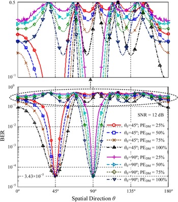
where I is, for static DM, the number of modulation states, e.g. 4 for QPSK, or, for dynamic DM, the symbol number T in a data stream. Λ in and S ov_in are the nth array element excitation for the ith symbol in the non-DM array and in the synthesized DM array, respectively. In noiseless free space, their modulus equal to the normalized modulus of corresponding B in_nonDM and B in_DM from the receiver side perspective. Generally, the larger the allowable range of the excitation vector lengths are, and the lower PE DM is, the better the DM system secrecy performance that can be achieved, see the simulated BER examples in Fig. 7. In other words, the enhanced secrecy performance, i.e. narrower main BER beams and more suppressed BER sidelobes are achieved at the cost of more energy radiated into the space by the DM arrays.
Simulated bit error rate spatial distributions in dynamic QPSK DM systems with different PE DM s for 45° and 90° secure communications. Signal to noise ratio is set to 12 dB.

The PE
DM
s in this example are determined by the parameter v
p
that is used for controlling the power of the generated orthogonal vectors
 ${\mathop {\bi W} \limits^{\rightharpoonup}}_{ov}$
, (17) and (18):
 $$P{E_{DM\_i}} = \displaystyle{1 \over {1 + \sum\nolimits_{p = 1}^{N - 1} {{{\left( {\displaystyle{1 \over {N - 1}} \cdot {v_p}} \right)}^2}}}} \times 100\%, $$
 $$P{E_{DM}}= \displaystyle{1 \over I} \cdot \sum\limits_{i = 1}^I {P{E_{DM\_i}}}. $$
It needs to be pointed out that for the example in Fig. 7
v
p
is not set to be a Gaussian distributed viable, instead we constrain
 ${\sum\nolimits_{p = 1}^{N - 1} {(1/(N - 1) \cdot {v_p})} ^2}$
to be a constant according to the required PE
DM
. This avoids very large array excitations from being synthesized as they are impractical in physical realizations.
B) DM array synthesis approaches when imposing some extra system requirements
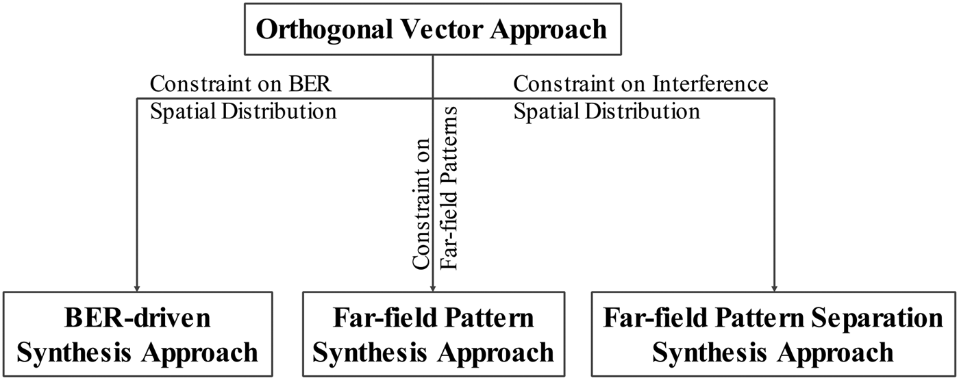
In Section IV.A, the universal DM synthesis method, i.e. the orthogonal vector approach, is presented. However, in some application scenarios, some other requirements on DM system properties may need to be considered. These requirements, or constraints, which have been investigated, include the BER spatial distribution, the array far-field radiation characteristics, and the interference spatial distribution. All three synthesis methods associated with each scenario can be viewed as seeking a subset of orthogonal vectors that satisfy prescribed DM system requirements.
The BER-driven [Reference Ding and Fusco13] and the constrained array far-field radiation pattern [Reference Ding and Fusco14, Reference Ding and Fusco15] DM synthesis approaches share a similar idea, i.e. via the iterative transformations between the array excitations and the required DM properties, namely the BER spatial distributions and the array far-field radiation patterns, the constraints on DM characteristics can be imposed. Since iteration processes are involved, these two methods are not suitable for dynamic DM synthesis.
Another DM array far-field pattern separation synthesis approach was developed in [Reference Ding and Fusco16]. Here by virtue of the far-field null steering approach, the DM array far-field radiation patterns can be separated into information patterns, which describe information energy projected along each spatial direction, and interference patterns, which represent disturbance on genuine information. By this separation methodology, we can identify the spatial distribution of information transmission and hence focus interference energy into the most vulnerable directions with regard to interception, i.e. information sidelobes, and in doing so submerge leaked information along unwanted directions. This method is closely linked to the orthogonal vector approach. In fact, the separated interference patterns can be considered as far-field patterns generated by the injected orthogonal vectors. However, it is more convenient to apply constraints, such as interference spatial distribution, with the pattern separation approach. This approach is compatible with both static and dynamic DM systems.
The relationships among the four DM synthesis approaches are illustrated in Fig. 8.
Relationships among the four DM synthesis approaches.

V. DM DEMONSTRATORS
Up to date there have been four DM demonstrators built for real-time data transmission.
The first demonstrator was constructed based on the passive DM architecture in 2008 [Reference Babakhani, Rutledge and Hajimiri20]. Since there are no effective synthesis methods associated with this type of DM structure, as was discussed in Section IV, no further development in this branch has been made afterwards.
Instead of passively excited DM array elements, the actively excited DM array demonstrator was built based on the analog structure in Fig. 2 [Reference Daly, Daly and Bernhard28]. Since the iterative BER-driven synthesis approach was adopted, only the static DM transmitter was achieved.
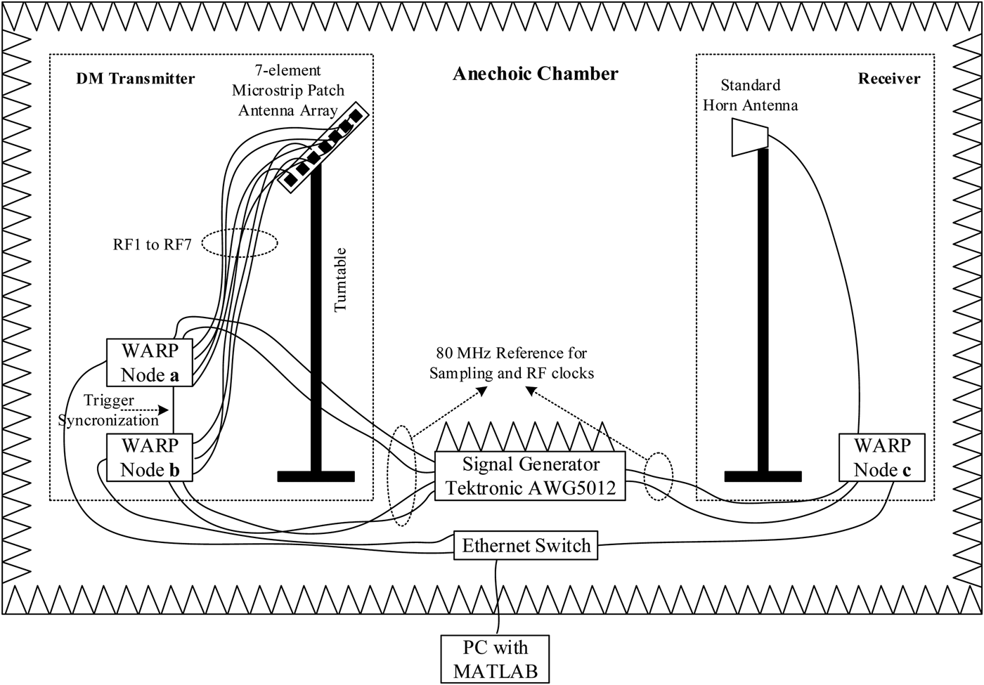
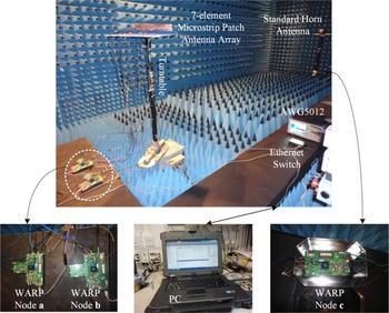
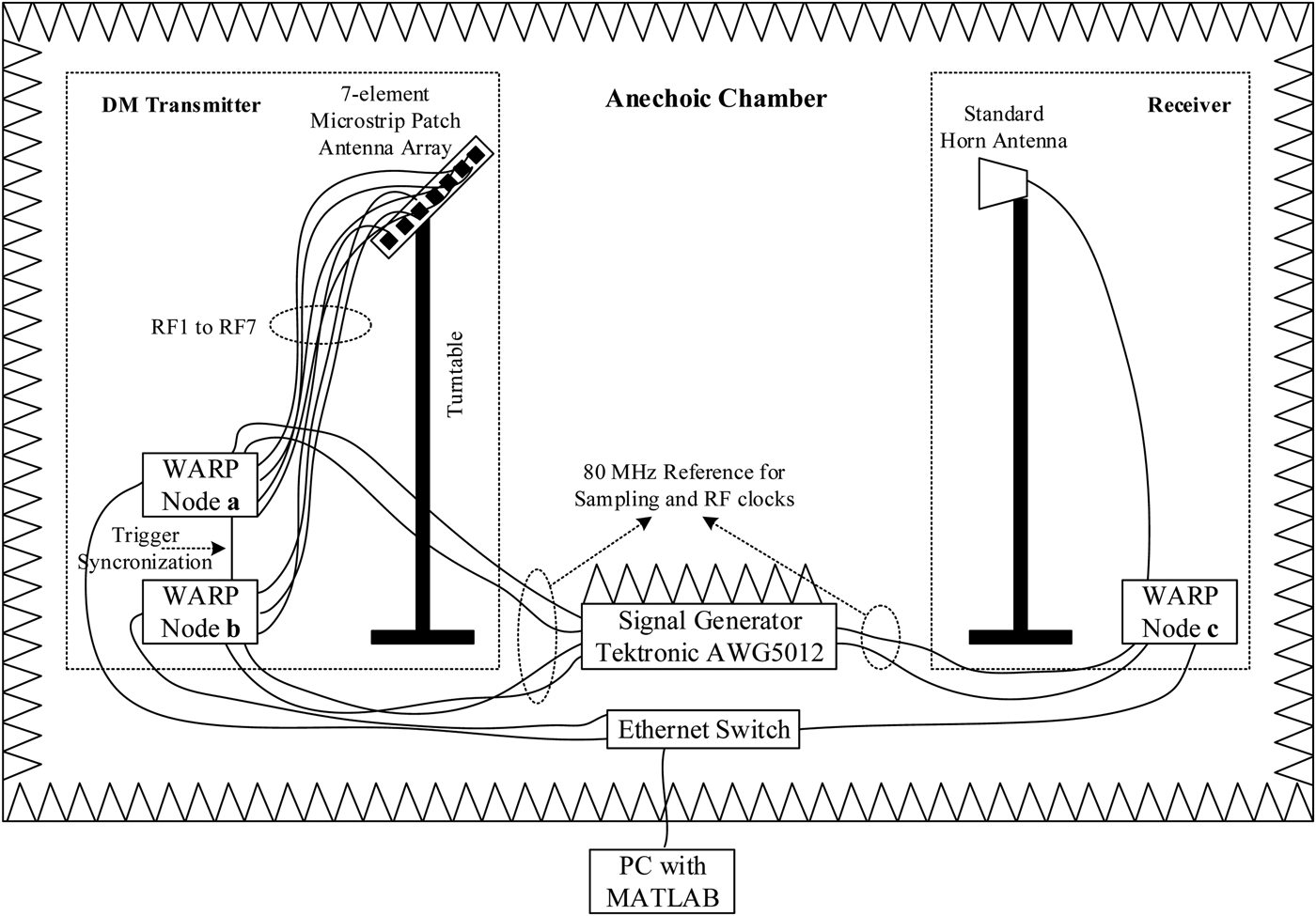
A 7-element digital DM demonstrator for 2.4 GHz operation [Reference Ding and Fusco43] was realized with the help of the Wireless Open-Access Research Platform (WARP) [44]. The block diagram and the photograph of the experimental setup are illustrated in Figs 9 and 10, respectively. This digital DM architecture is compatible with any synthesis methods presented in Sections IV.A and IV.B.
Block diagram of the digital DM experimental setup [Reference Ding and Fusco43].
Photographs of the digital DM experiment [Reference Ding and Fusco43].

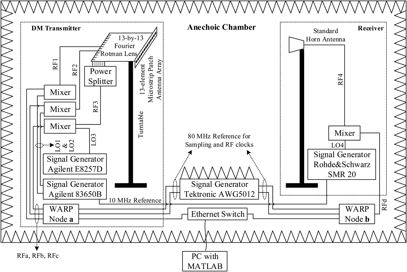
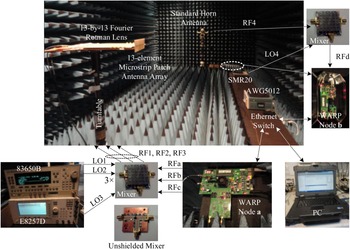
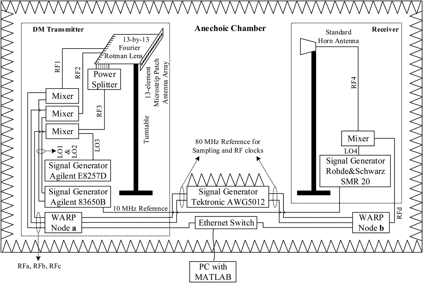
The other DM demonstrator [Reference Ding, Zhang and Fusco45] can be considered as hardware realizations of the orthogonal vector DM synthesis approach. This promising arrangement in [Reference Ding, Zhang and Fusco45] utilized the beam orthogonality property possessed by Fourier beam-forming networks to orthogonally inject information and interference along the desired secure communication direction. This structure avoids the use of RF switches [Reference Babakhani, Rutledge and Hajimiri20–Reference Chang, Babakhani and Hajimiri22, Reference Valliappan, Lozano and Heath34–Reference Hong, Song and Liu37] or analog reconfigurable RF devices as in [Reference Shi and Tennant18, Reference Shi and Tennant19, Reference Shi and Tennant23–Reference Shi and Tennant32], thus leads to an effective step toward practical field applications. Several system level experiments based on a 13-by-13 Fourier Rotman lens for 10 GHz operation were conducted in an anechoic chamber. One is for general demonstration purpose, the video of which can be found in [46]. Another Fourier Rotman lens DM experiment employed the WARP boards, which allowed the digital modulation being adopted and BER being measured [Reference Ding, Zhang and Fusco45]. The experimental setup is illustrated in Figs 11 and 12. The experimental results for both received constellation patterns and BER spatial distributions can be found in [Reference Ding, Zhang and Fusco45].
Block diagram of the 13-by-13 Fourier Rotman lens DM experimental setup [Reference Ding, Zhang and Fusco45].
Photographs of the 13-by-13 Fourier Rotman lens DM experiment [Reference Ding, Zhang and Fusco45].

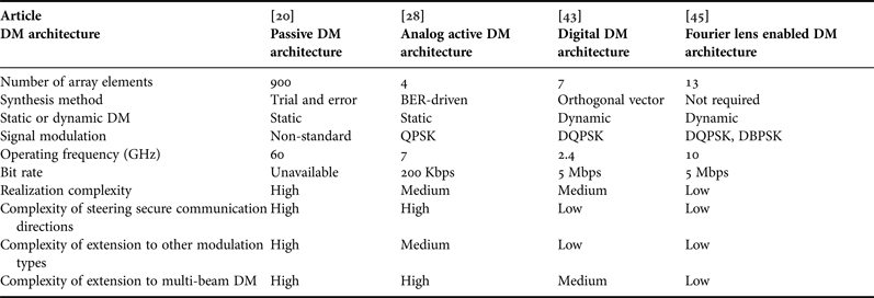
The four DM demonstrators are summarized in Table 2.
Summary of four DM demonstrators for real-time data transmission.
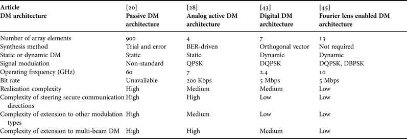
DQPSK, differential quadrature phase shift keying; DBPSK, differential binary phase shift keying.
VI. CONCLUSIONS AND RECOMMENDATION FOR FUTURE WORK
This paper reviewed the DM technology in every aspect. Specifically, Section II aimed to reveal the essence of DM technology and establish a universal DM description model. Section III was devoted to establishing universal figures of merit that allow direct comparison between different DM systems. The question of how a DM transmitter can be synthesized was addressed in Section IV, while the DM demonstrators for real-time data transmission, reported in the open literature were described and summarized in Section V.
From the conclusions above, it can be seen that a holistic framework of DM technology has been attempted. Within this framework, there are several important aspects that could be refined in the future, including:
-
• In [Reference Zhang, Ding and Fusco17], it was mentioned that it was the beam orthogonality property possessed by the Fourier transform beamforming networks (FT-BFNs) that enabled the DM functionality. However, in terms of successfully constructing DM transmitters, it is required that only beam orthogonality along the desired communication direction occurs, i.e. the far-field patterns excited by the interference applied at the relevant beam ports have nulls along the direction where the main information beam projects. Whereas, the main beam projected by the interference signal applied at each beam port lies at the null of the information pattern. Alignment of the nulls in this way is not strictly required as all that is needed for DM is that interference occurs everywhere except along the projected information direction. This means that the strict Fourier constraint can be relaxed to some extent. The extent of relaxation that can be applied could be investigated.
-
• It is imperative to extend DM technology for the applications under wireless multipath environment. Some initial attempts have been made in [Reference Shi and Tennant30, Reference Ding and Fusco47] using simplified multipath models. To be more convincing, a complex multipath channel model extracted from a real indoor environment would be helpful. Furthermore physical implementations and experiments on real-time data transmission are of works of interest.
-
• Almost all the reported DM work is on single-beam DM systems where only one information data stream is securely conveyed along one prescribed direction. It is natural to consider developing multi-beam DM systems, which have the capability of projecting multiple independent information data streams into different spatial directions, while simultaneously distorting information signal formats along all other unselected directions. This multi-beam DM concept was first suggested in 2008 [Reference Babakhani, Rutledge and Hajimiri20]. However, since then no real development has been made until the dual-beam Fourier lens based DM systems presented in [Reference Ding, Zhang and Fusco45]. Similar to single-beam DM, multi-beam DM technology should be systematically investigated from the aspects of the mathematical model, assessment metrics, synthesis approaches, and physical implementations.
ACKNOWLEDGEMENT
This work was sponsored by the Queen's University of Belfast High Frequency Research Scholarship.
 Yuan Ding received his Bachelor's degree from Beihang University (BUAA), Beijing, China, in 2004, received his Master's degree from Tsinghua University, Beijing, China, in 2007, and received his Ph.D. degree from Queen's University of Belfast, Belfast, UK, in 2014, all in Electronic Engineering. He was a RF Engineer in Motorola R&D Centre (Beijing, China) from 2007 to 2009, before joining Freescale Semiconductor Inc. (Beijing, China) as a RF Field Application Engineer, responsible for high power base-station amplifier design, from 2009 to 2011. He is now a Research Fellow at the ECIT Institute, Queen's University of Belfast, Belfast, UK. His research interests are in antenna array and physical layer security. He was the recipient of the IET Best Student Paper Award at LAPC 2013 and the recipient of the Young Scientists Awards in General Assembly and Scientific Symposium (GASS), 2014 XXXIst URSI.
 Vincent Fusco holds a personal chair in High Frequency Electronic Engineering at Queen's University of Belfast. His research interests include active antenna and front-end MMIC techniques. He is Head of the High Frequency Laboratories at QUB where he is also Director of the International Centre for System on Chip for Advanced Microwireless. Professor Fusco has published over 450 scientific papers in major journals and in referred international conferences. He has authored two text books, holds patents related to self-tracking antennas and has contributed invited papers and book chapters. He serves on the technical program committee for various international conferences including the European Microwave Conference. He is a Fellow of both the Institution of Engineering and Technology and the Institute of Electrical and Electronic Engineers. In addition, he is a Fellow of the Royal Academy of Engineers and a Member of the Royal Irish Academy. In 2012, he was awarded the IET Senior Achievement Award and the Mountbatten Medal.