I. INTRODUCTION
With the rapid development of aerospace, aircraft, and automotive industries, increasing requirements of the lightweight material for engineering components were put forward in the past decades. Reference Horstemeyer, Yang, Gall, Mcdowell, Fan and Gullett1,Reference Mordike and Ebert2 Magnesium alloys containing rare earth elements are of low density and high strength. It is noted that the recently developed Mg–Gd–Y–Zr magnesium alloys indicate remarkable precipitation hardening, resulting in significantly improved strength at both room and elevated temperature, and creep resistance is superior to that of a commercial WE54 alloy. Reference Anthony, Kamado and Kojima3,Reference Anthony, Kamado and Kojima4
A lot of papers have been published related to microstructure and mechanical properties of the Mg–Gd–Y–Zr alloys. Anyanwu et al. Reference Anthony, Kamado and Kojima3 investigated the effect of the Y:Gd ratio on age hardening characteristics and high temperature tensile properties of the Mg–Gd–Y–Zr alloys. He et al. Reference He, Zeng, Peng, Gao, Nie and Ding5,Reference He, Zeng, Peng, Gao, Nie and Ding6 proposed a precipitation sequence during isothermal aging which involved α-Mg supersaturated solid solution (S.S.S.S.) → metastable β″ (D019) → metastable β′ (cbco) → metastable β1 (fcc) → stable β (fcc). Nodooshan et al. Reference Nodooshan, Liu, Wu, Rao, Zhou, He, Ding and Mahmudi7 investigated the effect of the Gd content on the microstructure, age hardening response, and mechanical properties of the Mg–xGd–3Y–0.5Zr alloys. Given the results in the above literature, Mg–10Gd–3Y–0.5Zr (GW103) alloy exhibits excellent mechanical properties compared with the other Mg–Gd–Y–Zr alloys.
It is well known that fatigue failure is mainly responsible for service failures of structural applications. Knowledge on the fatigue behavior is critical for the application of the Mg–Gd–Y–Zr alloys in engineering components. Investigations have been conducted on the fatigue behavior of the Mg–10Gd–3Y–0.5Zr alloy in the recent years. Dong et al. Reference Dong, Liu, Song, Zhang, Ding and Korsunsky8 reported that peaking aging treatment can significantly improve the high-cycle fatigue strength and life of the extruded GW103 alloy. Mirza et al. Reference Mirza, Chen, Li and Zeng9 found that an extruded GW103 alloy exhibited nearly symmetrical hysteresis loops in tension and compression low-cycle fatigue. Similar symmetric hysteresis loops were also reported for extruded GW83 Reference Wang, Dong, Jiang and Ding10 and GW123 Reference Yin and Li11 alloys. Previous works mainly focus on the fatigue behavior of the extruded Mg–Gd–Y–Zr alloys, but most of the complicated engineering components are produced by sand casting. Therefore, it is necessary to further investigate the fatigue behavior of the sand-cast Mg–Gd–Y–Zr alloy. The current work aims to investigate the influence of heat treatment on cyclic deformation and low-cycle fatigue behavior of sand-cast GW103 alloy.
II. MATERIAL AND EXPERIMENTS
The Mg–10Gd–3Y–0.5Zr alloy used in this study was produced by low-pressure sand casting. The material was prepared from high-purity Mg (>99.95%), Mg–25Gd (wt%), Mg–25Y (wt%), and Mg–30Zr (wt%) master alloys in an electric resistance furnace under the mixed atmosphere of CO2 and SF6 with the ratio of 100:1. Then the melt was filled into low-pressure casting machine. The actual chemical composition of the alloy was determined to be Mg–9.84Gd–3.26Y–0.46Zr (wt%) by an inductively coupled plasma analyzer (ICP; Plasma400, PerkinElmer Inc., Waltham, Massachusetts). With reference to previous heat treatment results, Reference Cao, Liu, Li, Wu, Xiao, Wang and Ding12 solution treatment of specimens was carried out at 525 °C for 12 h and cooled to room temperature in the air. Aging treatment was carried out at 250 °C for 10 h after solution treatment. For the sake of convenience, the above heat treatment states can be simply named as sand-cast-T6.
Low-cycle fatigue tests were conducted on a computerized fatigue testing system (Instron electro Plus E10000, Canton, Massachusetts) in air at ambient temperature. Cyclic deformation experiments were controlled by a full reversed cyclic tension-compression loading at total strain amplitudes of 0.25, 0.3, 0.35, 0.4, 0.5, 0.6, and 0.7%, according to the low-cycle fatigue life between 1000 and 100,000 cycles to simulate engineering application. The number of specimen tested at each strain amplitude depends on the actual experimental result because limited specimens should be tested in the region of low-cycle fatigue as many as possible. The microstructures and fatigue fracture surfaces of the studied alloys were observed via optical microscope (OM; Axio Observer A1, ZEISS, Oberkochen, Germany) and scanning electron microscope (SEM; Philips 505, Amsterdam, The Netherlands), respectively. Phase composition was scanned by X-ray diffractometer (XRD) using Ni-filtered Cu Kα radiation.
III. RESULTS
A. Microstructure and tensile properties
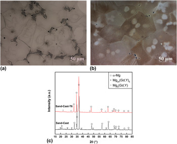
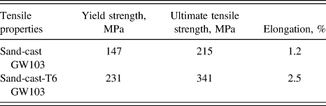
Optical microstructures of the sand-cast and sand-cast-T6 GW103 alloys and XRD patterns are shown in Fig. 1. The microstructure of the sand-cast alloy consisted of the equiaxed α-Mg matrix and network eutectic compounds distributed along grain boundaries [Fig. 1(a)]. The XRD analysis indicates that the sand-cast GW103 alloy mainly consists of a α-Mg solid solution and Mg24(Gd,Y)5 secondary phase. As can be seen from Fig. 1(b), there exist hardly any residual eutectic compounds in the microstructure after aging treatment. Some small granular black dots were unevenly distributed along grain boundaries. These black dots were a small cubic shaped phase (γ phase) and β′ precipitation phase. According to the XRD analysis and previous reports, the β′ phase has a composition Mg5(Gd,Y) and plays the major role in hardening the alloy. Reference He, Zeng, Peng, Gao, Nie and Ding6,Reference Cao, Liu, Li, Wu, Xiao, Wang and Ding12,Reference Zheng, Li, Tan, Xu, Luo and Chen13 The average grain sizes of sand-cast and sand-cast-T6 alloys determined by the linear intercept method were 58 and 76 μm, respectively. Tensile properties of the tested alloy are listed in Table I. Reference Chen, Liu, Wu, Li, Li, Zhang and Ding14 After T6 heat treatment, the yield strength and ultimate tensile strength increased by approximately 57.1% and 58.6%, respectively.
Optical microstructure of the (a) sand-cast and (b) sand-cast-T6 GW103 alloy and (c) XRD patterns of the alloy.

Tensile properties of the sand-cast and sand-cast-T6 GW103 alloys.

B. Cyclic deformation
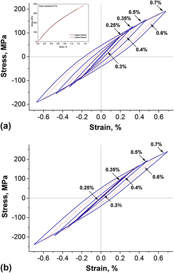
Figure 2 illustrates the effect of strain amplitudes on the shape of stabilized stress–strain hysteresis loops for the GW103 alloy in different heat treatment states, where all the loops at the half-life cycles are plotted. For a sand-cast alloy at the strain amplitude higher than 0.35%, it can be seen from Fig. 2(a) that the cast alloy nearly displayed symmetrical hysteresis loops. To examine tension-compression symmetry in detail, an inset [located at the upper left corner of Fig. 2(a)] showed the comparison of the upper branch with the lower branch of the stress–strain hysteresis loop at the strain amplitude of 0.7%. The lower branch was rotated 180° and then removed to coincide with the upper branch, and two branches seemed to overlap each other, indicating a nearly symmetrical hysteresis loop. It can be observed that the yield strength of tension was a little higher than that of compression, which indicated a weak Bauschinger effect. Using the same method to verify other hysteresis loops at the lower strain amplitude, it can be found that the extent of symmetry decreased with a decreasing strain amplitude. After aging treatment [Fig. 2(b)], the sand-cast-T6 alloy displayed similar nearly symmetrical hysteresis loops at the high strain amplitude. When the strain amplitude was lower than 0.4%, there was a linear relation between stress and strain, which indicated slight plastic deformation. It can also be seen that peak tensile and compressive stress of a stabilized hysteresis loop of the sand-cast-T6 alloy was apparently higher than that of the sand-cast alloy at each strain amplitude.
Stabilized stress–strain hysteresis loops at the half-life cycles for (a) sand-cast and (b) sand-cast-T6 GW103 alloys.

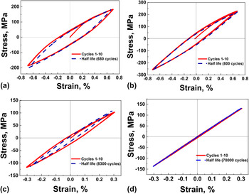
Figure 3 shows the stress–strain hysteresis loops of the sand-cast and sand-cast-T6 GW103 alloys at two strain amplitudes of 0.7 and 0.3%. The first 10 cycles and half-life cycles were plotted to show the evolution of the shapes of stress–strain hysteresis loops with increasing loading cycles.
Stress–strain hysteresis loops of cast GW103 alloy: (a) sand-cast, Δε/2 = 0.7%; (b) sand-cast-T6, Δε/2 = 0.7%; (c) sand-cast, Δε/2 = 0.3%; and (d) sand-cast-T6, Δε/2 = 0.3%.

At the high strain amplitude of 0.7% [Fig. 3(a)], the sand-cast GW103 alloy seemed to be a similar hysteresis loop of magnesium alloy containing a rare earth (RE) element. Both the upper branch and lower branch of the stress–strain curve displayed a concave shape for first 10 cycles and half-life cycles. It was reported that RE-free Mg alloys exhibited asymmetrical hysteresis loops and the branches evolved from a concave shape to sigmoidal shape with increasing loading cycles, as a result of the twinning dominated in the cyclic deformation. Reference Wang, Dong, Jiang and Ding10,Reference Mirza, Wang, Bhole, Friedman, Chen, Ni, Xiao and Ma15–Reference Chen, Wang, Wu, Liu, Stoica, Wu and Liaw17 The half-life cycles of the sand-cast alloy reached a tensile peak stress of 183.5 MPa and a compressive peak stress of 197.9 MPa. After aging treatment, half-life cycles of the alloy exhibited significant increasing strength, namely, sand-cast-T6 alloy, reached a tensile peak stress of 229.0 MPa and a compressive peak stress of 257.6 MPa. It is noticed in Fig. 3(b) that the sand-cast-T6 alloy displayed a softening effect by comparing the first 10 cycles with half-life cycles. Instead, the sand-cast alloy displayed a hardening effect with increasing loading cycles. At the low strain amplitude of 0.3%, Fig. 3(c) also displays nearly tension-compression symmetry, and slight plastic deformation was observed from the hysteresis loop of the sand-cast alloy. The sand-cast-T6 alloy almost kept elastic deformation during the cyclic loading in Fig. 3(d), which suggested that 0.3% strain amplitude of the alloy possibly near to strain fatigue limit.
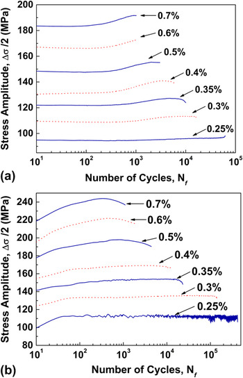
Figure 4 shows the evolution of stress amplitudes with respect to the number of cycles at different applied strain amplitudes. For the sand-cast GW103 alloy [Fig. 4(a)], the alloy exhibited first cyclic hardening with increasing loading cycles then slight softening near ultimate failure at the applied strain amplitude higher than 0.35%. Particularly, a cyclic hardening behavior was apparent at the high strain amplitude. At the strain amplitude lower than 0.35%, the stress amplitude remained unchanged over the entire fatigue life, probably due to merely slight plastic deformation in the specimen at the low strain amplitude. As is seen from Fig. 4(b), the sand-cast-T6 alloy exhibited rapid cyclic hardening firstly and then displayed a long stage cyclic softening until final failure at the strain amplitudes higher than 0.35%. In comparison with the sand-cast alloy, the aged alloy exhibited more rapid and dramatic cyclic hardening at the same strain amplitude. When strain amplitudes were lower than 0.35%, the sand-cast-T6 alloy exhibited rapid cyclic hardening firstly and then displayed a similar long stage cyclic stabilization until final failure. The stable cyclic stress response was due to the balance between hardening and softening effects at lower strain amplitudes.
The evolution of stress amplitudes with respect to the number of cycles at different applied strain amplitudes for (a) sand-cast and (b) sand-cast-T6 GW103 alloys.

C. Fatigue life
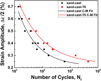
Figure 5 shows the strain amplitude as a function of the number of cycles to failure (N f, i.e., fatigue life) for sand-cast and sand-cast-T6 GW103 alloys. Each scatter in the figure represented one fatigue experiment. It was obvious that the low-cycle fatigue life of the sand-cast-T6 alloy was higher than that of the sand-cast alloy at all strain amplitudes. The fatigue life difference between two studied alloys was slight at the high strain amplitudes. However, when the strain amplitude was below 0.35%, the variability in the fatigue life of the studied alloy exceeded one order of magnitude, indicating that fatigue resistance was significantly improved after aging treatment. As shown in Fig. 2, the sand-cast-T6 alloy almost kept elastic deformation at the strain amplitude below 0.35%. In other words, micro-plastic deformation did not cause too much fatigue damage to the alloy, which contributed to a high fatigue life.
Strain amplitude-fatigue life curves of the sand-cast and sand-cast-T6 GW103 alloys.

Strain amplitude versus fatigue life could be expressed as the following three-parameter equation according to Coffin–Manson relation:
 $${\left( {{{\Delta \varepsilon } \over 2} - {\varepsilon _0}} \right)^\xi }{N_{\rm{f}}} = C\quad ,$$
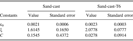
where Δε/2 is the strain amplitude and N f is the fatigue life. The remaining three symbols ε0, ξ, and C are theoretical strain fatigue limit, fatigue ductility exponent, and fatigue ductility coefficient, respectively. All three parameters are related to material essential attributes, which can be obtained by best fitting the experimental data. As seen from Fig. 5, the fitted curves were consistent with experimental results. The fitted values and corresponding errors of three parameters for the alloy in different states are listed in Table II. The theoretical strain fatigue limits (ε0) of sand-cast and sand-cast-T6 alloys are 2.1% and 2.3%, respectively. When the applied strain amplitude is lower than the fatigue limit, it will not cause any damage to the alloy.
The fitted values and corresponding standard errors of three parameters.

D. Fatigue fracture
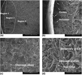
Figure 6 shows SEM micrographs of the fatigue fracture surfaces of the sand-cast GW103 alloy after 2349 cycles at 0.5% strain amplitude. The overall fracture surface displayed three distinct regions [Fig. 6(a)]: fatigue crack initiation region (Region 1), fatigue crack propagation region (Region 2), and collapse fracture region (Region 3). It is well known that fatigue cracks usually initiate from the casting defects during cyclic loading when there are some casting defects in the specimen. It was observed clearly that cracks nucleated at multiple sites of oxides or inclusions in Fig. 6(b). The arrows indicated some oxides and inclusions, which were crack initiation preferential areas. Figure 6(c) shows that the fatigue crack propagation region was characterized by amounts of cleavage steps. Region 2 displayed a sectorial shape in the overall fracture surface, and the area of the crack propagation region enlarged with an increasing strain amplitude in the experiment. For the studied alloys, the specimen would experience rapid failure at the end of the crack propagation stage. In other words, the fatigue life was dominated by crack initiation and propagation regions. In the collapse fracture region [Fig. 6(d)], the fracture surface demonstrated quasi-cleavage characteristics similar to axial tensile fracture, displaying numerous cleavage planes, tear ridges, and secondary cracks.
SEM micrographs of the fatigue fracture surfaces of the sand-cast GW103 alloy after 2349 cycles at 0.5% strain amplitude: (a) overall fracture surface, (b) crack initiation region, (c) crack propagation region, and (d) collapse fracture region.

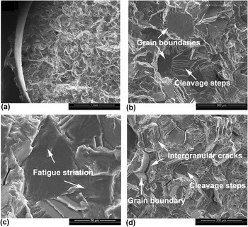
Figure 7 shows SEM micrographs of the fatigue fracture surfaces of the sand-cast-T6 GW103 alloy after 5919 cycles at 0.5% strain amplitude. As shown in Fig. 7(a), fatigue crack mainly originated from the specimen surface. When there are little casting defects in the specimen interior, the fatigue crack usually nucleated at the specimen surface due to surface grains which are of the weakest strength and maximum alternate stress during cyclic deformation. Reference Li, Wang, Luo, Peng and Zhang18 Different from the sand-cast alloy, the crack propagation region exhibited amounts of grain boundaries and fewer cleavage steps [Fig. 7(b)], suggesting that the fracture surface displayed a mixture pattern of intergranular and transgranular crack propagation. It should also be noted that some fine fatigue striations were observed in the crack propagation region of the sand-cast-T6 alloy [Fig. 7(c)]. Each fatigue striation could be assumed to be perpendicular to the crack propagation direction and roughly represents a loading cycle. The spacing of fatigue striations could reflect the crack propagation rate and was related to the fatigue life. Reference Mirza and Chen19 It can be observed that the fracture surface was mainly characterized by massive grain boundaries and intergranular cracks in Fig. 7(d), which was similar to the brittle intergranular fracture, indicating worse ductility after aging treatment.
SEM micrographs of the fatigue fracture surfaces of the sand-cast-T6 GW103 alloy after 5919 cycles at 0.5% strain amplitude: (a) crack initiation region, (b) crack propagation region, (c) fatigue striation, and (d) collapse fracture region.

IV. DISCUSSION
A. Tension-compression symmetry and cyclic hardening
It was generally believed that tension-compression symmetry was mainly associated with the microstructure of material, such as grain size, precipitates, and crystallographic textures, which are decisive factors of the deformation mechanism.
Reference Wang, Dong, Jiang and Ding10,Reference Begum, Chen, Xu and Luo16,Reference Chen, Wang, Wu, Liu, Stoica, Wu and Liaw17,Reference Mirza, Chen, Li and Zeng20
Dislocation slip and twinning are two important deformation mechanisms in the hexagonal close-packed (hcp) structure of a magnesium alloy. At room temperature, the three dominant sets of slip systems are (0002)
 $\left\langle {11\bar 20} \right\rangle$
, which are inadequate for plastic deformation. Magnesium alloy exhibited a strong propensity for mechanical twinning because twinning had a low critically resolved shear stress.
Reference Zeng, Han, Ke, Dietzel, Kainer and Atrens21
In the work, it can be found that the extent of symmetry increased with an increasing strain amplitude (Figs. 2 and 3), which suggested that the deformation mechanism during different strain amplitudes had changed. As reported, the symmetrical hysteresis loop was predominated by dislocation slip deformation, similar to those of face-centered cubic material.
Reference Mirza, Wang, Bhole, Friedman, Chen, Ni, Xiao and Ma15,Reference Mirza and Chen19
Twinning was responsible for an asymmetrical hysteresis loop, such as RE-free extruded magnesium alloys.
Reference Chen, Wang, Wu, Liu, Stoica, Wu and Liaw17,Reference Zeng, Han, Ke, Dietzel, Kainer and Atrens21
It was confirmed that the small grain size and precipitates are unfavorable for twinning deformation at room temperature.
Reference Mirza, Chen, Li and Zeng20
Therefore, the cyclic deformation for the sand casting GW103 alloy might be dominated by the dislocation slip at the high strain amplitude but twinning at the low strain amplitude.
B. Cyclic deformation mechanism
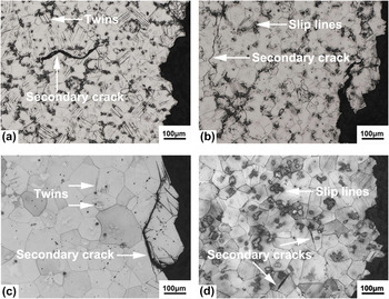
Figure 8 shows optical micrographs of the longitudinal section of the fracture surfaces. To investigate distinction of the cyclic deformation mechanism between low and high strain amplitudes, strain amplitudes of 0.3 and 0.7% were selected in each condition. For a sand-cast GW103 alloy at the strain amplitude of 0.3% [Fig. 8(a)], it can be clearly observed that most grains experienced numerous parallel residual twins. The twins almost penetrated the whole grain and were perpendicular to the grain boundary, which progressively increased with the act of twinning in the cyclic deformation, leading to a slight cyclic hardening. In contrast, hardly any residual twins were observed at the high strain amplitude of 0.7% [Fig. 8(b)]. Instead, slip lines sparsely distributed at a portion of grains’ interior, which was closely related to strain cyclic hardening during the cyclic deformation shown in Fig. 4(a). The cyclic hardening phenomenon is mainly associated with dislocation interactions and pileups, for the reason that the hcp structure of the magnesium alloy facilitates twinning, which impedes the motion of dislocations and causes the formation of dislocation pileups. Reference Begum, Chen, Xu and Luo22–Reference Lou, Li, Boger, Agnew and Wagoner24 It can also be seen that the secondary crack originated from eutectic compounds and extended hundreds of micron by means of a transgranular propagation mode.
Optical micrographs of longitudinal section of the fracture surfaces of the GW103 alloys: (a) sand-cast, Δε/2 = 0.3%, N f = 16,667; (b) sand-cast, Δε/2 = 0.7%, N f = 1371; (c) sand-cast-T6, Δε/2 = 0.3%, N f = 156,243; and (d) sand-cast-T6, Δε/2 = 0.7%, N f = 1604.

After aging treatment, at a low strain amplitude of 0.3% [Fig. 8(c)], it can be observed that only a few residual twin bands and secondary cracks are located in the vicinity of the fatigue fracture surface, in contrast with massive twins distributed at the whole longitudinal section of the sand-cast specimen. Fewer residual twins were responsible for cyclic stabilization at the low strain amplitude in Fig. 4(b). As reported in Ref. Reference Brown, Agnew, Bourke, Holden, Vogel and Tomé25, twinning was associated with a low stress region and accommodated the deformation due to tension and compressive stress. There was hardly any secondary crack on the area far away from the fracture surface as well, indicating that the low strain amplitude was difficult to cause crack development. For the sand-cast-T6 alloy at a high strain amplitude of 0.7%, similar characteristic [Fig. 8(d)] had been observed, i.e., the grains’ interior presented abundant parallel slip lines, which indicated that dislocation slips might contribute to plastic deformation during low-cycle fatigue. Compared with sparse slip lines in the sand-cast alloy, the presence of abundant slip lines resulted in a more rapid and remarkable strain hardening response during the cyclic deformation shown in Fig. 4(b). In addition, it can be observed that a few secondary cracks started at dislocation slip lines of grain interior and terminated at the grain boundary. It was believed that dispersed precipitates improve grains’ interior strength and retard secondary crack propagation. Consequently, it was more difficult for secondary cracks to spread across the grains.
V. CONCLUSIONS
Cyclic deformation and low-cycle fatigue behavior of the sand-cast and sand-cast-T6 GW103 alloys were conducted at the strain amplitude ranging from 0.25 to 0.7%. The following conclusions could be drawn from this investigation:
-
(1) The stress–strain hysteresis loops for both sand-cast and sand-cast-T6 GW103 alloys display near tension-compression symmetry at the applied strain amplitudes, and the extent of symmetry increases slightly with an increasing strain amplitude.
-
(2) The sand-cast alloy exhibits first cyclic hardening with increasing loading cycles and then slight softening near ultimate failure at the strain amplitude over 0.35%. Whereas, the sand-cast-T6 alloy exhibits rapid cyclic hardening firstly and then displays a long stage cyclic softening until final failure at the strain amplitude is higher than 0.35%.
-
(3) The fatigue life of the sand-cast-T6 alloy is more than 105 cycles at the strain amplitudes lower than 0.35%, which exceeds one order of magnitude compared with that of the sand-cast alloy.
ACKNOWLEDGMENTS
This work is supported by National Key Research and Development Program of China (No. 2016YFB0701205), Science Innovation Foundation of Shanghai Academy of Spaceflight Technology (Nos. SAST2015047 and SAST2016048), and Research Program of Joint Research Center of Advanced Spaceflight Technologies (No. USCAST2015-25).