Introduction
Hydrogels are biomaterials consisting of hydrophilic polymer networks that have been widely researched in various fields of biomedicine, including tissue engineering scaffolds, controlled release drug delivery systems, and biosensors. The reason hydrogels have such wide applications resides in its tissue-like properties of high water content and superb flexibility.Reference Peppas, Hilt, Khademhosseini and Langer1–Reference Bryant and Anseth3 Predominantly, both natural and synthetic hydrogels have been investigated for producing tissue engineering scaffolds, which provide a natural mimicking environment to promote cell growth and tissue regeneration. Natural hydrogels such as hyaluronic acid (HA), collagen, gelatin, fibrin, and agarose have largely been used to fabricate scaffolds because of their innate biomimetic chemical, biological, and mechanical properties.Reference Yamanlar, Sant, Boudou, Picart and Khademhosseini4–Reference Mauck, Yuan and Tuan7 However, since natural hydrogels are not as conducive to fabrication processes as synthetic hydrogels, more research interest has been focused on synthetic hydrogels, such as poly(ethylene glycol) (PEG), poly(vinyl alcohol) (PVA), poly(acrylic acid) (PAA), poly(lactic-co-glycolic acid) (PLGA), and poly(L-lactic acid) (PLLA).Reference Pattison, Wurster, Webster and Haberstroh8–Reference Jintang, Beckemper, Gillner and Wang11 Synthetic hydrogels have two advantages compared to natural hydrogels: First, the mechanical and chemical properties of synthetic hydrogels are more controllable. By adjusting the molecular weight and cross-linking density of a polymer, synthetic hydrogels of various stiffness and water content can be designed and produced for scaffolds in a variety of applications, such as bone, cartilage, and muscle. The surface chemical properties of synthetic hydrogels can also be modified by attaching growth factors or peptides on the surface. Second, the properties of synthetic hydrogels are more reproducible. A specific synthetic hydrogel can be accurately reproduced by employing the same molecular weight monomer and cross-linking time in a consistent manufacturing environment.
PEG, one of the most extensively used synthetic hydrogel biomaterials, was chosen for this work. Three properties of PEG have made it an attractive material for tissue engineering scaffolds. First, PEG is biocompatible but does not interact with proteins or cells since it is inert to most biological molecules. This neutrality makes it an ideal base material upon which the desired bio-properties can be built. Additionally, researchers have shown that by grafting different peptides on the backbone of PEG, the hydrogel can be modified to be both bioactive and biodegradable.Reference Gombotz, Guanghui, Horbett and Hoffman12, Reference West and Hubbell13 Second, various PEG derivatives possess properties that allow fabrication via photopolymerization. The most widely used PEG derivative in tissue engineering is diacrylated PEG (PEGDA). Upon enough light irradiation, the acrylate groups in PEGDA will be cross-linked with each other to form a cross-linked polymer. This property enables PEGDA to be readily fabricated through photopolymerization. Third, the large variety of PEG derivatives grant researchers the freedom to select specific variants based on the desired stiffness necessitated by the location and function in a human body. PEG scaffolds with different moduli can be fabricated by changing the molecular weight of PEG prepolymers or by diluting PEG prepolymers in other solvents before fabrication, such as water or phosphate buffered saline (PBS).
Over the last 20 years, a variety of methods have been developed and utilized to fabricate hydrogel scaffolds. These methods include, but are not limited to, solvent casting/salt leaching, gas foaming, electrospinning, phase separation, solid freeform fabrication, membrane lamination, electron beam lithography (EBL), and nano-imprinting.Reference Nam, Yoon and Park14–Reference Qiu, Teichman, Wang, Elmaanaoui, Gamez and Milner22 Although these methods have been successfully applied in scaffold fabrication, they do not provide the ideal control of scaffold properties. EBL and nano-imprinting are intrinsic two-dimensional fabrication methods, which do not accurately mimic the natural three-dimensional growth environment for cells. Solvent casting/salt lamination, gas foaming, electrospinning, phase separation, and membrane lamination are capable of fabricating three-dimensional scaffolds, but relinquish precise control of the size and shape of the inner structure of the scaffolds. Solid freeform fabrication is capable of fabricating three-dimensional scaffolds with precise control of the scaffold geometry, but the fabrication resolution is limited to the range of tens to hundreds of microns, which is too large to accurately mimic the in vivo submicron/nanoscale biological cues. In light of the rapid advancement in tissue engineering, researchers have searched for an alternative fabrication method that is capable of fabricating three-dimensional submicron/nanoscale scaffolds with precise control of the geometry. Femtosecond laser-induced two-photon polymerization (TPP) is one promising technique that fulfills these requirements. Researchers have been using TPP to fabricate three-dimensional submicron/nanoscale structures that are widely used in optics and biology.Reference Maruo, Nakamura and Kawata23–Reference Qiu, Wang, Paranjape and Milner25 In our work, a femtosecond laser was employed to fabricate submicron/nanoscale three-dimensional scaffolds for tissue engineering with precise control of the size and shape. We also used our femtosecond laser to fabricate two-dimensional submicron scale topographical patterns for basic biological research.
Principle and application of femtosecond laser-induced two-photon polymerization
The foundation of TPP is two-photon absorption (TPA), a process by which one molecule is excited to a higher energy electronic state by simultaneously absorbing two photons. The concept of TPA was first predicted by Goeppert-Mayer in 1931.Reference Göppert-Mayer26 However, it was not until after the invention of the laser that researchers were able to observe two-photon excited fluorescence in the experiment. Following the invention of the ultrafast femtosecond laser, which was able to emit a laser beam with pulse width at the femtosecond scale, researchers such as Sugioka et al. have expanded the application of TPA into the micron/nano fabrication field, where TPP was introduced. The peak power of a femtosecond laser is much higher than a continuous wave laser or a nanosecond laser. The extremely high photon density in the center portion of a femtosecond laser beam allows non-linear laser-material interaction, specifically, two-photon polymerization. Due to the extremely high photon density requirement of TPP and the Gaussian distribution of the laser beam energy intensity over the cross-section, the TPP reaction is restricted to the central portion of the laser beam. Thus it is feasible to make features even smaller than the diffraction limit through TPP. This distinction grants a clear advantage to TPP in contrast to traditional single photon polymerization (SPP).Reference Qiu, Wang, Milner, Teichman, Neev, Glickman and Chan27, Reference Serbin, Egbert and Ostendorf28 The other advantage of TPP over SPP is the three-dimensional fabrication capability of TPP. A femtosecond laser emits infrared or near-infrared wavelengths, at which most polymers do not absorb any photon energy. Therefore, a femtosecond laser beam is able to penetrate a photoresist and induce polymerization inside of the liquid without cross-linking the material in its path.
In order to optimize the resolution of TPP and select a suitable TPP material, it is necessary to investigate the mechanism of TPP. TPP is a chain reaction process that transforms short monomers in liquid state to long polymers in solid state by simultaneously absorbing two photons using a femtosecond laser beam as an energy source. In order to induce this chain reaction, a photoinitiator, a reagent that can easily generate a large amount of free radicals upon laser irradiation, must be added to the monomer solution. The process of TPP is depicted in Equations 1 and 2.


Equation 1 demonstrates the process of free radical generation. In the equation, I is the photoinitiator, I* is an intermediate state of the photoinitiator after simultaneously absorbing two photons, and R • is a free radical. After being generated, free radicals will attack the C=C bonds of the monomers in the solution and produce monomers that contain a free electron, as described in Equation 2. COORm represents a generic acrylate monomer. The monomer depicted in Equation 2 is in a family of materials with acrylic functional groups, which is widely used in TPP. These monomers with a free electron will continue attacking other monomers to form oligomers with free electrons, as described in Equation 3,

where RM • is the product of Equation 2, and M is the monomer. The chain reaction propagates until two radicals neutralize each other. Since the cross-linked monomer chain forms the backbone of the polymerized solid structure, the chemical and mechanical properties of the solid structure are mostly determined by the monomer. By using different monomers or different molecular weights of the same monomer, polymers with various chemical and mechanical properties can be easily fabricated.
Hydrogel preparation and laser fabrication system setup
PEG diacrylate (PEGDA, MW 700) was purchased from Sigma-Aldrich. To induce chain photopolymerization, 1% (w/v) of the photoinitiator Irgacure 819 was dissolved in PEGDA by stirring the liquid for two hours on a hot plate. The concentration of the photoinitiator was carefully controlled so as not to damage the cells, because Ovsianikov et al. have demonstrated that photoinitiator with concentration higher than 2% (w/v) is toxic to cells.Reference Ovsianikov, Malinauskas, Schlie, Chichkov, Gittard, Narayan, Löbler, Sternberg, Schmitz and Haverich24 To fabricate high-resolution three-dimensional structures, the PEGDA prepared must be uncontaminated and therefore transparent so that the laser beam will not be blocked or diffracted by the impurities in the liquid. To remove the impurities, the mixture of PEGDA and Irgacure 819 was forced out through a 0.2 micron pore size syringe filter. The setup of the TPP laser fabrication system is shown in Figure 1. The laser used in the system was a 800 nm Ti:sapphire femtosecond laser, and a 100X oil immersion objective lens was used to focus the laser beam into the hydrogel to induce polymerization. A 15-micron diameter pinhole was placed at the focal point of the lenses in the beam expander to filter out the diffraction noise at the periphery of the beam.
Experimental setup of femtosecond laser fabrication of hydrogels. CCD, charge-coupled device.

The laser power can be continuously adjusted by rotating a beam attenuator. The pattern to be fabricated was first designed by the computer-aided design software AutoCAD, and then the CAD pattern was converted to G-code (a universal controlling code used in computerized numerical control machines) through an open-source G-code converter. The G-code was then loaded to the Tracer program, a stage control program developed by the stage manufacturer. The Tracer program controls both the stage and an automated shutter on the laser to irradiate and photopolymerize the sample according to the designed pattern. Since the refractive index of PEGDA was visibly changed after polymerization, the fabricated structure can be observed instantly during the fabrication process. Thus the fabrication process can be monitored in situ with a charge-coupled device camera. A filter must also be used to block out the UV spectra of the illuminating light to avoid overexposure of the PEGDA prepolymer during fabrication.
Fabrication of nanoscale three-dimensional scaffolds and two-dimensional patterns
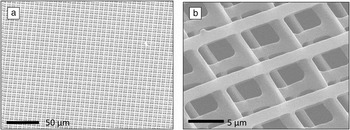
Three-dimensional submicron/nanoscale scaffolds are widely used in tissue engineering as well as in basic biological research. One application in basic biological research is in investigations of cancer cell transmigration, where cancer cells migrate through endothelial tissues and blood vessels that enclose the tumor to establish secondary tumors.Reference Grimstad29, Reference Nicolson30 We fabricated a PEGDA “woodpile structure” (Figure 2) as a biological model to quantitatively investigate cancer cell transmigration. These cell studies are ongoing. Six-layer woodpile scaffolds were made for this purpose; the results are demonstrated in Figure 2. The distance between adjacent lines in the woodpile scaffold is 8 microns, which is smaller than the typical size of cancer cells and can be changed according to the size of the cells. The stiffness of the scaffold can be changed by using different molecular weight PEGDA as well as by changing the concentration of PEGDA in PBS.
Scanning electron microscopy images of the three-dimensional PEGDA scaffold: (a) Six-layer woodpile scaffold of 1 μm-wide lines with a pitch of 8 μm; (b) magnified view of the scaffolds. The distance between adjacent layers is 3 μm.

Cell behavior on a patterned surface has also been extensively investigated recently, with emphasis on chemical and topographic patterning.Reference Bettinger, Langer and Borenstein31 Chemical patterning is generated by selectively positioning chemical cues, such as growth factor or peptides, on the cell adhesion surface, while topographic patterning is fabricated by varying the shape and dimension of the patterns on the surface. Micro/nanoscale patterning is of great importance in tissue engineering research because the biological cues in extracellular matrix are at the micro/nanoscale. Researchers have been investigating cell adhesion, migration, stem cell differentiation, and tissue regeneration stimulation by using a micro/nano pattern to mimic the in vivo environment.Reference Lim, Shaughnessy, Zhou, Noh, Vogler and Donahue32
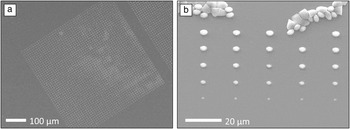
Femtosecond laser fabrication is a versatile tool for fabricating both chemical and topographical patterns. By changing the amount of growth factor and peptide in the hydrogels, patterns with a chemical gradient can be made. To demonstrate this capability, we used the femtosecond laser to make a two-dimensional array of hydrogel microdots of different size and thus different amounts of growth factor chemicals.Reference Miller, Li, Kanade, Weiss, Walker and Campbell33 Various sizes of topographical patterns can be made by changing the scanning path, power, and exposure time of the laser beam. The material we used was a hybrid material of PEGDA and Cultrex 3D Culture Matrix according to the optimized ratio of 9:1 (v/v). Cultrex 3D Culture Matrix is a type of standardized basement membrane extract, which is a thin sheet of fibers that underlies the epithelium, specially produced for 3D culture studies. With the growth factor already incorporated in the material, it is then ready to be used for cell culture without further treatment. However, Cultrex alone is not suitable for laser fabrication, since its polymer chain does not have any functional groups that can cross-link with each other under laser irradiation. Thus when mixed with PEGDA, it can provide the foundation for photopolymerization. We tested hybrid materials with different PEGDA/Cultrex ratios for fabrication. It was found that Cultrex clusters, which would not only make it impossible to quantitatively control the growth factor concentration but also scatter the laser beam during fabrication, were formed in the mixture when the PEGDA/Cultrex volume ratio was lower than an optimum of 9:1. The photoinitiator Irgacure 819 (1% w/v) was added to the mixture to provide free radicals for the two-photon polymerization process. By adjusting the laser power and exposure time, microdots of various sizes could be made on the surface of glass coverslips. By lifting or lowering the objective lens, we could change the height of the microdots. Scanning electron microscopy (SEM) images of the microdots array are shown in Figure 3. For proof of concept, we made a microdot array in a 500 μm by 500 μm area. Dose tests were conducted to demonstrate that the size of the microdots could be changed by adjusting the focal position of the laser beam, as shown in Figure 3b.
Scanning electron microscopy images of the microdot array made from PEGDA/Cultrex hybrid material: (a) A 500 μm by 500 μm microdot array with a dot diameter of 2 μm and a pitch of 20 μm; (b) dose test of microdot fabrication, the laser exposure time decreased from the top row to the bottom row.

Integration with a nano-imprint process
Though femtosecond laser-induced TPP is a versatile nano-fabrication method, it contains a serious disadvantage; it is a slow point-by-point process. The fabrication process of a nanostructure can last for hours, depending on the complexity of the structure. For two-dimensional nanostructures, which have been widely used in studies of cell adhesion, migration, and differentiation, we have streamlined the fabrication process by combining femtosecond laser fabrication with the nano-imprint lithography technique.Reference Zhang, Han and Chen34 Nano-imprint lithography has been widely used in making high-resolution structures, such as biomedical sensors and photonic crystals. Traditionally, researchers used expensive cleanroom facilities in conjunction with EBL and reactive ion etching to make nano-imprint molds, resulting in a complex and lengthy process. Our research has proved that a femtosecond laser is a promising alternative tool for making nano-imprint molds in an efficient and economical way.
The first step in making nano-imprint molds with a femtosecond laser is the selection of mold material. We chose a polymer as the mold material in order to exploit femtosecond laser-induced TPP. A few criteria were considered when selecting the best polymer. First, after adding a proper photoinitiator, the polymer must be able to be cross-linked by a femtosecond laser. We chose a polymer containing an acrylic group because its units could readily cross-link with each other upon exposure to the laser beam. Second, the polymer must be rigid enough to imprint nanostructures as designed and also to endure hundreds of imprinting processes. The ideal polymer must therefore have a short chain and high molecular weight to provide high rigidity. Third, the polymer should either be anti-adhesive or contain certain groups on its polymer chain to bond with an anti-adhesive layer, which could be deposited after the mold is made. Dipentaerythritol pentaacrylate (DPPA) was chosen out of these considerations. Its monomer has five acrylic groups, which makes it a fast curing resin under exposure to a femtosecond laser. Its short length chain makes it sufficiently rigid to imprint hydrogels. Moreover, each molecule of DPPA has one hydroxyl group, which makes it possible to covalently bond an anti-adhesive layer on it.
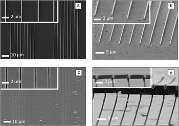
Before making the mold, an adhesive layer must be formed on the mold substrate so that the DPPA can bond to a glass substrate. We used 3-trichlorosilyl propyl methacrylate (TPM) as the bonding layer, and the layer was deposited on the substrate by placing both the substrate and 3-trichlorosilyl propyl methacrylate in a mixture of heptane and carbon tetrachloride. The residue was washed away by carbon tetrachloride. The PEGDA substrate to be imprinted was treated in the same way to enhance adhesion. Nanostructures were then patterned on the treated substrate by using a femtosecond laser to make the mold. Then, the mold was coated with an anti-adhesive layer to enhance release of the mold from imprinted structures after the imprinting process. Fluorosilane—tridecafluoro-1,1,2,2-tetrahydrooctyl-1 trichlorosilane (TFTT) was selected due to its low surface energy and its readiness to be coated. To coat the fluorosilane layer on the mold, the mold and a few drops of fluorosilane were placed in a vacuum for one hour, and the fluorosilane was coated on the mold surface by an evaporation process. The imprinting process was conducted in a mask aligner; the detailed process was described in a previous publication.Reference Zhang, Han and Chen34 A coverslip with PEGDA precursor solution on it was brought into contact with the mold and then photopolymerized under UV light to retain the shape of the mold. The mold and the glass substrate were then detached from each other. Figure 4 shows the SEM images of both the mold and the imprinted nanostructures. As demonstrated by the images, the imprinting process transferred the nanopatterns on the mold to PEGDA with consistency and high accuracy. After multiple imprinting operations, the mold was still intact, and no residual PEGDA adhered to the mold surface. We also showed the cross-sectional view of the imprinting PEGDA structure by perpendicularly cutting the structure with a scalpel. The exposed side view of the structure demonstrates the imprinting accuracy not only in the horizontal dimension but also in the vertical dimension.
Scanning electron microscopy images of the imprinted PEGDA structures and the dipentaerythritol pentaacrylate (DPPA) mold after imprinting: (a) DPPA mold of 400 nm-wide lines with a pitch of 5 μm; (b) side view of the DPPA mold after imprinting; (c) imprinted PEGDA structures; and (d) vertical view of the PEGDA trench cross-section.

Summary and perspective
Throughout our experiments, we employed femtosecond laser-induced two-photon polymerization to make nanoscale tissue engineering scaffolds with poly(ethylene glycol) diacrylate (PEGDA). PEGDA is approved by the U.S. Food and Drug Administration (FDA), and PEG-based hydrogels have been widely utilized in the fabrication of tissue-engineering scaffolds with three-dimensional microscale structures. However, research efforts to fabricate three-dimensional nanoscale structures in tissue engineering scaffolds using PEGDA have been lacking. This work will bridge the gap.
The integration of femtosecond laser fabrication with nano-imprint lithography greatly increased the fabrication speed of making two-dimensional structures. Using a mask aligner and imprint mold made by a femtosecond laser, one can quickly transfer the nanopattern in the mold to the PEGDA sample.
Due to the fact that the in vivo stimuli of cells are at the submicron/nanoscale, we expect these nanoscale PEGDA scaffolds to better mimic the in vivo environment than their larger micron-scale counterparts. We plan to conduct cell studies with these scaffolds to explore their potential capability in heart muscle and neuron regeneration, as well as in cancer cell and stem cell research.
Acknowledgments
This work is supported by grants from the Office of Naval Research (N00014–07–1-0609) and the National Science Foundation (CMMI 1130894) to S.C.