1. Introduction
Neurological and musculoskeletal disorders such as spinal cord injury [Reference Snoek, Ijzerman, Hermens, Maxwell and Biering-Sorensen1], stroke [Reference Nichols-Larsen, Clark, Zeringue, Greenspan and Blanton2], and cerebral palsy [Reference Law, Lee, Fung, Yan, Gudushauri, Wang, Ip and Chow3] severely impair hand mobility and reduce quality of life. Many affected individuals lose the ability to perform basic activities of daily living (ADLs), while age-related muscle weakness in the elderly population further limits independence [Reference Weening-Dijksterhuis, De Greef, Scherder, Slaets and Van Der Schans4]. Stroke is a leading cause of death and disability in China [5], with its incidence expected to rise alongside an aging population [Reference Gao, Jiang, Sun, Ru, Sun, Wang, Wang, Jiang, Feigin, Wang and Wang6]. The human hand plays a vital role in daily functions, serving both as a mechanical and sensory interface [Reference Feix, Romero, Schmiedmayer, Dollar and Kragic7, Reference Vatan, Nefti-Meziani, Davis, Saffari and El-Hussieny8]. Restoring hand functionality is therefore a key target in neurorehabilitation.
Existing research has increasingly focused on robotic exoskeletons to support functional training and daily activities for individuals with upper-limb impairments [Reference Pires, dos Santos and Tinoco9–Reference Gull, Bai and Bak11]. Upper-limb exoskeletons are wearable robotic devices that physically interface with the human body to provide motion assistance or augmentation. Among these, hand exoskeletons have been extensively developed for both rehabilitation and assistive applications [Reference du Plessis, Djouani and Oosthuizen12, Reference Gherman, Zima, Vaida, Tucan, Pisla, Birlescu, Machado and Pisla13]. Existing designs can be broadly categorized into fixed-frame (stationary) systems and portable (wearable) devices [Reference Cempini, Cortese and Vitiello14]. While stationary systems offer high precision and force output, they are typically bulky and unsuitable for daily use. In contrast, portable systems emphasize lightweight, compact, and cost-effective designs, making them suitable for home-based rehabilitation. Wearable hand exoskeletons are commonly classified into rigid mechanisms and soft robotic gloves (SRGs) [Reference du Plessis, Djouani and Oosthuizen12, Reference Cempini, Cortese and Vitiello14–Reference Zhang, Orban, Wu, Liu, Wang, Elsamanty, Yang and Guo21]. Compared with rigid structures, SRGs provide improved compliance, safety, and comfort for prolonged wear [Reference du Plessis, Djouani and Oosthuizen12, Reference Chu and Patterson22–Reference Kaviri, Fesharaki and Sadeghnejad25].
Recent advances in SRGs have largely focused on tendon- and cable-driven mechanisms, which enable effective force transmission while allowing remote actuation to reduce hand inertia [Reference Alicea, Xiloyannis, Chiaradia, Barsotti, Frisoli and Masia26]. Hybrid tendon-driven designs combining soft and rigid elements have been proposed to support finger flexion–extension and thumb opposition while maintaining portability [Reference Kim, Choi, Kim, Jeong and Cho27]. Several studies have demonstrated low-cost, home-based glove systems with improved wearability [Reference Ceccarelli, Vaisson and Russo28], optimized tendon routing for kinematic compatibility [Reference Silva, Lourenço, Ulhoa, Dias, da Cunha, Tonetto, Villani, Vimieiro, Lepski, Monjardim and Andrade29], and fabric-based motor-tendon gloves assisting both finger flexion and extension in stroke rehabilitation [Reference Ismail, Ariyanto, Setiawan, Hidayat Paryanto and Nuswantara30]. Modular tendon-driven gloves actuated by twisted string actuators (TSAs) offer adaptable assistance for diverse patient needs [Reference Dragusanu, Piroli and Malvezzi31], while task-specific TSA-based glove that integrates flexible fabrics to improve grip force, dexterity, and muscle efficiency [Reference An, Park, Kim, Lee, Cho and Koo32]. Underactuated tendon-driven systems, such as Exo-Glove Poly III, generate multiple grasping strategies using a single actuator, reducing hardware complexity while preserving functional versatility [Reference Kim, Choi, Kim, Kang, Cheon and Al33]. Other works have addressed tendon-sheath modeling and parameter optimization to mitigate friction and slack in Bowden cable transmissions [Reference Yuan, Fan and Wu34].
Alternative soft actuation approaches have also been explored. Fabric-based pneumatic gloves have demonstrated functional improvements in finger range of motion (RoM) and ADL performance [Reference Feng, Yang, Sun, Lao, Rui, Gu and Member35], while pneumatically actuated gloves with inertial measurement unit (IMU) sensing enable reliable motion estimation [Reference Davarzani, Ahmadi-Pajouh and Ghafarirad36]. Magnetorheological cable-driven designs introduce adjustable rigid-soft anchoring to enhance comfort and stability [Reference Lu, Li, Lai, Wang, Yu, Lu, Wei, Wang and Song37]. Shape memory alloy (SMA) actuators have been employed for compact, lightweight glove actuation [Reference Vellaiyan, Jeong and Kim38]. Additional approaches include passive extension mechanisms [Reference Maciejasz, Eschweiler, Gerlach-Hahn, Jansen-Troy and Leonhardt39], spring-like tendon designs [Reference Gan, Vazquez, Dalton, Qin, Zhang and Quintero40], and sensorized gloves for whole-hand tracking in virtual-reality-based rehabilitation [Reference Li, Chen, Zhou, Xie, Gao, Xiao, Dai, Xu, Wang and Zhou41]. Collectively, these studies highlight diverse strategies for achieving wearable, safe, and effective hand assistance, while motivating continued research toward practical, intuitive, and adaptable soft robotic glove systems.
SRGs function as wearable end-effectors that restore hand movement and interaction capabilities in individuals with impaired hand function. Their design requires balancing functionality, comfort, and usability [Reference Xu, Wu and Zhu42]. The selection of materials is fundamental; soft textiles or elastomers should offer durability, flexibility, and comfort [Reference Irzmańska and Kropidlowska43–Reference Motti and Caine45]. A multilayered structure is typically adopted, comprising an inner comfort layer, a functional actuation layer, and an outer protective layer. Cable routing is crucial for efficient motion transmission and finger force generation. Tendons can be strategically routed to achieve desired flexion or extension while minimizing friction and maintaining alignment with the finger joints [Reference Chen, Yu, Tu, Lyu, Tang, Ou, Fu and Xue46]. Cable paths and attachment points are also essential for providing effective motion and avoiding discomfort. Sensor integration, such as bend or pressure sensors, provides feedback on motion and contact forces [Reference Borghetti, Sardini and Serpelloni47, Reference Wang, Song, Naqash, Zheng, Xu and Zhang48], improving control accuracy and adaptability.
SRGs inherently allow passive degree of freedom like finger abduction/adduction, enabling more natural hand movement than rigid designs. Donning and doffing is another critical design factor [Reference Rodríguez-Fernández, Lobo-Prat and Font-Llagunes49]. The attachment and closure mechanisms, such as clasps, laces, Velcro, or other fastening systems, enhance accessibility for individuals with limited mobility. Esthetics and ergonomics are also vital for long-term acceptance, especially in daily-use contexts [Reference Motti and Caine45, Reference Huang, Wu and Yu50]. A holistic approach to SRG design, therefore, demands balancing actuation efficiency, user comfort, durability, and appearance. Glove designs employing underactuated fingers inherently offer less precise control than fully actuated configurations [Reference Nilsson, Ingvast, Wikander and Von Holst51]. As the number of fingers increases, the associated kinematic and control complexity also grows. Nevertheless, underactuated designs remain attractive for wearable applications due to their lower cost, reduced number of actuators, and lighter, more compact structure.
Cable-driven SRGs typically employ two main actuation architectures: rotary spool mechanisms (RSMs) and lead-screw-based linear mechanisms (LSLMs). RSM actuators, comprising motor-driven spools that wind and unwind cables, are widely used for finger flexion–extension [Reference In, Kang, Sin and Cho17, Reference Xu, Wu and Zhu42]. The different types include circular spools [Reference In, Kang, Sin and Cho17], cam-shaped spools [Reference Xu, Wu and Zhu42], and synergy-based multi-spool design driven by a single motor that replicate natural grasp postures [Reference Xiloyannis, Cappello, Khanh, Yen and Masia15]. RSMs provide large cable displacement and compact integration, but they often require additional components such as pretensioning, locking, and slack-prevention mechanisms [Reference Xiloyannis, Cappello, Khanh, Yen and Masia15, Reference In, Kang, Sin and Cho17]. Complex feeder systems, such as one-way bearings and capstans, are used to prevent cable slippage [Reference Xiloyannis, Cappello, Khanh, Yen and Masia15]. The robotic hand in [Reference Xiloyannis, Cappello, Binh, Antuvan and Masia52] drives three pairs of antagonistic tendons, with its control system incorporating an electromagnetic clutch to secure hand positions. In [Reference Xu, Wu and Zhu42], a one-way bearing and rubber wheel are utilized, whereas [Reference In, Kang, Sin and Cho17] employs a capstan mechanism integrated with a one-way clutch to achieve passive braking. Most RSM-based designs lack active locking mechanisms, resulting in continuous power consumption during prolonged object grasping.
In contrast, LSLMs convert motor rotation into linear motion through a threaded lead screw, directly tensioning the cable via a moving nut. LSLMs offer a simpler structure, energy-efficient holding capability, and inherent mechanical locking. Studies have demonstrated LSLM-actuated gloves using cable power transmission [Reference Nilsson, Ingvast, Wikander and Von Holst51] and push–pull Bowden cables [Reference Nycz, Butzer, Lambercy, Arata, Fischer and Gassert53] to facilitate finger motion. In addition to the RSM and LSLM, another approach in [Reference Gerez and Liarokapis54] employs a four-output differential mechanism that evenly distributes torque among four finger cables, enabling the grasping of irregular objects. Most hand exoskeletons adopt underactuated designs to balance portability and functionality [Reference In, Kang, Sin and Cho17, Reference Xu, Wu and Zhu42, Reference Xiloyannis, Cappello, Binh, Antuvan and Masia52, Reference Gerez and Liarokapis54, Reference Chiara, Silvestro, Jos, Symposium and Robotics55]. Typically, a single actuator drives multiple fingers, commonly the thumb, ring or index, and middle, sufficient for most grasping tasks. This reduces actuator count, weight, and complexity while maintaining essential ADL capabilities. Compared to RSMs, LSLM-based actuators offer a compact, robust, and low-power solution well suited for wearable rehabilitation systems.
Beyond structural and actuation design, anticipating user intent is a key requirement for achieving natural and responsive exoskeleton control. Recent progress integrates physiological and biomechanical sensing to interpret human intention. The most well-known methods include electromyography (EMG), IMUs, and pressure/bend sensors. For instance, the SEM Glove employs pressure-sensitive sensors to assist in grasping and daily activities [Reference Radder, Prange-Lasonder, Kottink, Holmberg, Sletta, van Dijk, Meyer, Melendez-Calderon, Buurke, Rietman and Fukumoto56], while EMG-based control has been widely adopted in commercial systems such as the MyoPro [Reference Kelly, Tacy, Kesner and Harlan57], providing intuitive, muscle-driven actuation. However, EMG signals are highly individual-dependent, susceptible to electrode placement, skin impedance, and noise, and often unreliable in patients with muscle weakness or paralysis [Reference Anam and Al-Jumaily58, Reference Stewart, Christopher, Adams, Chen, Ashley, Stewart, Christopher and Adams59]. These limitations can restrict EMG’s usability in clinical and home-based rehabilitation. Bilateral (mirror) control offers an alternative strategy, where the healthy limb drives the impaired one [Reference Leonardis, Chisari, Bergamasco, Frisoli, Barsotti, Loconsole, Solazzi, Troncossi, Mazzotti, Castelli, Procopio and Lamola60, Reference Gassert and Dietz61]. This technique typically supports only ADLs involving the simultaneous use of both arms, such as lifting objects [Reference Brackenridge, Bradnam, Lennon, Costi and Hobbs62]. Although effective in restoring coordinated motion, it is limited to bimanual tasks and may constrain independent joint movement. Therefore, developing self-contained, intention-driven control mechanisms remains a priority to control the SRGs independently [Reference Park, Heo, Kim and Na63].
To enhance reliability, researchers have integrated different sensing modalities, including tactile [Reference Radder, Prange-Lasonder, Kottink, Holmberg, Sletta, van Dijk, Meyer, Melendez-Calderon, Buurke, Rietman and Fukumoto56, Reference Wang, Ding and Mei64], bend [Reference Borghetti, Sardini and Serpelloni47], optical, and IMU and distance sensors [Reference Weiner, Starke, Rader, Hundhausen and Asfour65]. Innovations include IMU-based finger tracking [Reference Morales-Cruz, Capalbo, Caroleo, Ceccarelli and Carbone66], voice-activated grasping [Reference Guo, Xu, Pradhan, Bravo and Ben-Tzvi67], and tongue-controlled interfaces [Reference Mohammadi, Knoche, Thøgersen, Bengtson, Kobbelgaard, Gull, Bentsen, Severinsen, Khan and Andreasen Struijk68]. However, modules relying on a single sensor can be limited in accurately detecting human intent during dynamic movements. Recent approaches therefore emphasize a multimodal sensing approach combining two sensors to enhance responsiveness and robustness [Reference Nilsson, Ingvast, Wikander and Von Holst51, Reference Hammond, Menguc and Wood69]. For instance, embedding pressure sensors in fingertips and bend sensors along finger segments allows detection of both contact forces and joint motion [Reference Hammond, Menguc and Wood69]. Such hybrid sensing systems enable context-aware, adaptive control, particularly beneficial for users with partial voluntary motion.
Hand paralysis and weakness resulting from neurological or musculoskeletal disorders severely affect independence and daily functionality. Although soft robotic gloves have shown promise for hand assistance and rehabilitation, many existing designs remain clinic-oriented, rely on complex sensing or calibration procedures, or lack sufficient adaptability for users with weak voluntary motion. To address these challenges, this study proposes a lightweight, cable-driven soft robotic intention-controlled glove exoskeleton designed through the co-design and integration of mechanical interface, underactuated actuation, and intention-based control, with a specific focus on safe, intuitive, and home-oriented use. The main contributions of this work are as follows:
(i) A compact, flexible glove subsystem supporting the ring, middle, and thumb fingers, with optimized tendon routing and embedded sensors to facilitate aligned, comfortable motion while capturing bending and contact interaction, enabling direct sensing of user intent at the hand interface. A detachable cable connector enables rapid donning/doffing, interchangeable glove sizes, and easy replacement using a single actuator unit, with integrated mechanical travel limits that constrain finger motion at the interface level. (ii) A compact lead-screw-based underactuated actuator with stroke amplification and cable-loop mechanism, allowing a single motor to drive multiple fingers and automatically adapt to diverse object shapes. Its self-locking property enables static grasp maintenance without continuous power, suitable for prolonged daily use. (iii) A multimodal intention-based control framework that leverages finger bending and fingertip pressure sensing to provide proportional, user-driven assistance. The system is optimized for individuals with weak grasp strength, allowing assistance to be triggered and modulated by partial voluntary motion and contact interaction, which can improve usability and robustness relative to prior approaches that rely on single-mode sensing or require extensive calibration.
Through the integration of these three main elements, SRIG-Exo achieves a unified system in which the soft glove interface with tendon routing and embedded sensors, along with the detachable connector, adaptive under-actuation, and intention-driven assistance, operate coherently. The rest of the paper is organized as follows. Section 2 outlines the materials and methods, covering the glove, linear actuator, and control system designs. Section 3 describes the experimental setup and presents the results. Section 4 discusses the limitations and future work, and Section 5 concludes the paper.
2. Materials and methods
This section provides a comprehensive overview of the SRIG-Exo system’s design and development methodology. It covers the device’s main components, including the sensor-embedded and tendon-routed soft robotic glove, the cable-tensioning linear actuator, and the active intention-based control system. The following subsections detail each of these elements.
2.1. SRIG-Exo system description
The overall architecture of the SRIG-Exo system is shown in Figure 1, which presents the mechanical structure and sensing layout of the glove together with the detachable cable connector and linear actuator designs. The system consists of three main subsystems: the soft glove module, the linear actuation unit, and the control system.
Overview of the SRIG-Exo device. The figure illustrates its main components, including the glove, detachable cable connector, and hardware box containing the linear actuator, battery, and control electronics. (a) Glove design showing embedded sensors and tendon routing. (b) Detachable cable connector assembly with connector 1 and connector 2, and the first and second joining parts where tendons from the glove and actuator are fixed, respectively. (c) CAD model of the compact lead-screw-driven linear actuator. (d) The SRIG-Exo glove worn on the user’s hand.

The soft glove module is fabricated from multilayer textile materials selected for comfort, flexibility, and mechanical strength. Flexible steel tendons run along the palmar side of the thumb, middle, and ring fingers to generate flexion forces. They pass along the phalanges and loop around the fingertips through low-friction Teflon guides to ensure smooth motion (Figure 1(a)). Pressure sensors embedded at the fingertips and bend sensors positioned on the dorsal surfaces of the fingers provide real-time feedback on user interaction and joint motion. The glove also incorporates a detachable cable connector, allowing quick attachment or replacement while maintaining precise cable alignment (Figure 1(b)). This is an essential feature for daily donning and doffing and for interchanging gloves of different sizes or materials.
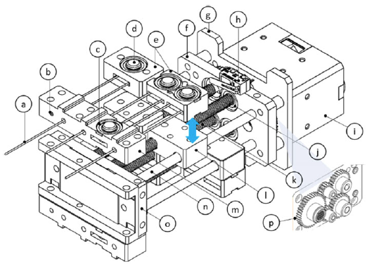
The linear actuation unit employs a lead-screw-based underactuated mechanism (Figure 1(c)). A compact DC servo motor drives a threaded rod, coupled to a traveling nut, which converts rotational motion into linear displacement. A loop-type cable routing mechanism is integrated to automatically distribute tendon tension among multiple fingers, enabling adaptive grasping of objects with different shapes without the need for separate actuators. This configuration effectively realizes under-actuation, reducing both weight and energy consumption while improving grasp adaptability. Mechanical stoppers at both stroke limits, along with software-defined position and torque limits, ensure operational safety by preventing excessive cable displacement or over-tightening.
The control and power module are housed in a lightweight 3D-printed enclosure that can be mounted on the user’s waist belt or upper arm to minimize distal loading. This module integrates the microcontroller board, linear actuator unit, and battery. The intention-based control algorithm utilizes real-time inputs from the bend and pressure sensors to interpret the wearer’s motion intent. When voluntary finger bending or contact pressure exceeds the preset thresholds (detailed in Section 2.4), the controller issues proportional actuator commands to pull the tendons and assist the grasp. This produces an intuitive, user-initiated assistance response while maintaining safe and natural interaction.
The integration of these three subsystems results in a lightweight, wearable, and intention-responsive glove capable of assisting functional grasping for individuals with partial hand mobility. The combination of a detachable cable connector, loop-based under-actuation, and hybrid sensing control distinguishes it from conventional cable-driven gloves, which typically rely on multiple actuators, rotary spool mechanisms, single-sensor modalities, or EMG-based control strategies. These subsystems, together with the intention-based control framework, are described in detail in the subsequent sections.
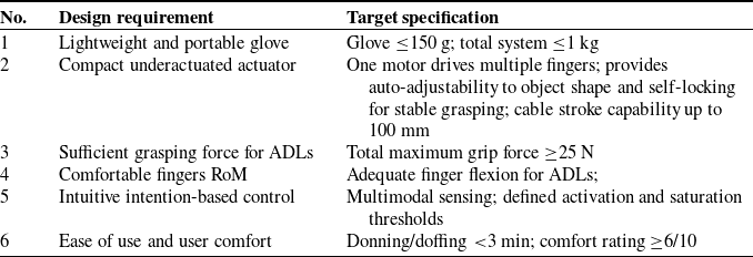
Furthermore, to guide the mechanical design, actuation strategy, and control architecture of the SRIG-Exo, key quantitative design requirements were established. These requirements define target specifications for wearability, assistive force, motion range, control responsiveness, and user comfort, ensuring the device is suitable for rehabilitation and daily activities. Table I summarizes the quantified requirements. These requirements provide a clear benchmark for evaluating design choices for the SRIG-Exo system and also guide the experimental validation.
Quantified design requirements of the SRIG-Exo.

A summary comparing the design requirements listed in Table I with the experimentally achieved results is provided in the discussion (see Section 4), validating the target specifications for glove weight, actuator performance, grasping force, finger motion, control responsiveness, donning/doffing time, and user comfort.
2.2. Mechanical design of the SRIG
The physical design of the soft robotic glove is illustrated in Figure 2. The glove itself is equipped with force sensing resistor (FSR) sensors (RP-C18.3-LT, Suzhou Leanstar Electronic Technology Co., Ltd., China) affixed to the underside of the fingertips and the bend (flex) sensors (FLEX 4.5, Suzhou Leanstar Electronic Technology Co., Ltd., China) positioned at the midpoints along the top side of the finger and artificial tendons routed in the thumb, middle, and ring fingers at the palmar side, respectively.
The SRIG-Exo: palmar (right side) and dorsal (left side) views of the soft glove showcasing its mechanical structure and integrated sensing components.

The tendon routing and under-actuation mechanism of the SRIG-Exo are illustrated in Figure 3, showing how a single motor drives multiple fingers through a looped cable configuration. The glove is primarily constructed from synthetic leather, with cut patches at the finger joints to enhance natural movement and comfort. It is essential to note that for optimal performance, custom-tailored gloves are recommended to fit the glove on the wearer’s hand precisely [Reference Secciani, Brogi, Pagliai, Buonamici, Gerli, Vannetti, Bianchini, Volpe and Ridolfi70].
Schematic of the tendon routing and under-actuation mechanism. (a) Overview of the SRIG-Exo showing tendon paths, teflon tubes, and Bowden cables driven by a single motor. (b) Detailed routing for two fingers (finger a and finger B) through the detachable connector, illustrating the looped configuration between the glove and actuator.

The connected artificial tendons constructed from 0.6 mm diameter flexible steel cables (ɸ 0.6 mm 7 × 7, Taizhou Jianyi Stainless Steel Products Co., Ltd., China), combined with Teflon (PTFE), are chosen to minimize friction between the synthetic leather and the cables. Each tendon is assigned to a particular finger of the glove. The artificial tendon traverses along both sides (medial and radial sides) of the bottom of each finger, forming a loop rather than going through the center, indicating a dual-sided routing pattern. This tendon loop converges near the finger’s base, and the tendons follow the palm routing. This proximity to the volar side generates a moment arm around the finger joint’s axes, facilitating flexion and adduction movements [Reference Park, Heo, Kim and Na63]. In addition, a strap is stitched to the proximal phalanx of the thumb to support the abduction adjustments, as depicted in Figure 2 (left side), thereby enhancing the hand’s grasping ability [Reference Kelly, Tacy, Kesner and Harlan57, Reference Kang, Choi, Lee and Cho71]. The primary objective is to improve hand grip strength, particularly on the thumb, middle, and ring fingers.
A splint has been devised to secure the cables within the glove. Notably, the glove’s palm features an opening near the edges of the proximal phalanges of the fingers, as depicted in Figure 2 (right side). This opening feature serves a dual purpose: first, it enhances the range of tendon displacement, facilitating greater finger bending. Second, it simplifies the process of putting on and taking off the glove. Additionally, two Velcro (hook-and-loop) straps are incorporated into the palm to fasten the glove securely onto the hand. These straps provide added support to withstand the forces exerted by the tendons on the hand. These tendons pass through the palm routing of the glove and are shown in Figure 2 (right side).
Teflon tubes are used to reduce friction within the tendon routing paths, thereby enhancing the longevity of the designated routes by minimizing wear and tear. This Teflon works as a pulley-type mechanism, guiding the artificial tendons. All tendons originate from a detachable connector that links the actuator unit to the glove, as depicted in Figure 1(d). The electrical wires of the FSR sensor traverse through the top of the finger, positioned beneath the flex sensor. The electrical wires of both sensors are passed through the dorsal side of the glove to avoid hindrances, while the palmar side of the glove comes into contact with objects. As a human–machine interface, the mechanical design of the SRIG-Exo must prioritize safety and ensure mechanically transparent operation. Therefore, mechanical travel limits are integrated on both the glove (within the detachable connector) and actuator sides to ensure safe and durable performance. The detachable connector is positioned on the palmar side of the forearm and secured with Velcro straps. Power transmission cables run along the arm, enabling easy detachment of the glove from the hardware box for replacement or interchange with other gloves. The actuators, controller, and batteries are housed in a compact hardware box (Figure 1) that can be worn remotely for convenient use.
2.2.1. Mathematical modeling
The schematic of the finger kinematics and tendon routing is developed to derive the forward kinematics of the finger, as illustrated in Figure 4. Additionally, Figure 5 presents the schematic depicting the sensor placement and the method used for angle measurement via the flex sensor.
Schematic of one-finger kinematic and tendon routing model (lateral side). The schematic drawing defines the tendons’ routing along each finger joint.

Schematic drawing defining the insertion of the sensors and the angle measurement method using the flex sensor, where
 $\theta _{f}$
is the measured angle.

In Figure 4,
 $\theta _{f,i}$
(i = 1, 2, 3) denote the joint angles of the metacarpophalangeal (MCP), proximal interphalangeal (PIP), and distal interphalangeal (DIP) joints, respectively. Similarly,
 $L_{f,i}$
represent the lengths of the proximal, middle, and distal phalanges, and the black circles
 $J_{f,i}$
indicate the corresponding finger joints. Notably, in the schematic of Figure 4 and in the forward kinematics and total finger flexion equations, indexed variables are written explicitly (e.g.,
 $\theta _{f1}$
–
 $\theta _{f3}$
,
 $L_{f1}-L_{f3}$
) for improved readability.
The flexor tendon is routed along the palmar side of the finger through small guiding tubes fixed at the midpoints of each phalanx, as illustrated in Figure 4. Accordingly,
 $l_{t,i}$
denote the tendon path lengths from the palm to the proximal phalanx, from the proximal to the middle phalanx, and from the middle to the distal phalanx, respectively.
 $\gamma _{i}$
represent the angles influenced by the tendon path geometry. The flexor tendon is shown in maroon color, the routing path for the tendon is shown in light blue, and the gray rectangles represent the straps that support the tension on the finger.
The geometric parameters
 $l_{t,i}$
can be determined from the geometry of the glove. The distances between the Teflon guide tubes mounted at the midpoints of adjacent phalanges, as well as between the palm-mounted guide tube and the proximal phalanx, are fixed by the glove design. The parameter
 $h_{i}$
denotes half of the finger thickness at i-th phalanx. For the default fully extended configuration (
 $\theta _{f1}=\theta _{f2}= \theta _{f3}=$
0°), the tendon path lengths are expressed in Eq. (1) as:
 \begin{equation}l_{t,i}=l_{i,a}+l_{i,b},\quad {i}= 1, 2, 3.\end{equation}
The tendon routing geometry introduces the angles
 $\gamma _{i}$
, which are computed using the law of cosines as given in Eq. (2):
 \begin{equation}\gamma _{i}=cos^{-1}\left(\frac{\left(\left(h_{i}\right)^{2}+\left(l_{i,a}\right)^{2}\right)+\left(\left(h_{i+1}\right)^{2}+\left(l_{i,b}\right)^{2}\right)-\left(l_{t,i}\right)^{2}}{2\sqrt{(\!\left(h_{i}\right)^{2}+\left(l_{i,a}\right)^{2}) (\!\left(h_{i+1}\right)^{2}+\left(l_{i,b}\right)^{2})}}\right),\quad {i}= 1, 2, 3.\end{equation}
During finger flexion, variations in joint angles
 $\theta _{f,i}$
result in changes in the tendon path lengths due to cable displacement. The change in tendon length for each segment is approximated in Eq. (3) as:
 \begin{equation}{\unicode{x1D6E5}} l_{t,i}=l_{t,i}-\frac{D_{C}}{3},\quad {i}= 1, 2, 3.\end{equation}
where
 $D_{C}$
denotes the total cable displacement and can be computed using Eq. (12).
Accordingly, the variation in the tendon routing angles is given by Eq. (4):
 \begin{equation}{\unicode{x1D6E5}} \gamma _{i}=cos^{-1}\left(\frac{\left(\left(h_{i}\right)^{2}+\left(l_{i,a}\right)^{2}\right)+\left(\left(h_{i+1}\right)^{2}+\left(l_{i,b}\right)^{2}\right)-\left({\unicode{x1D6E5}} l_{t,i}\right)^{2}}{2\sqrt{(\!\left(h_{i}\right)^{2}+\left(l_{i,a}\right)^{2}) (\!\left(h_{i+1}\right)^{2}+\left(l_{i,b}\right)^{2})}}\right),\quad {i}= 1, 2, 3.\end{equation}
Now, the joint angles
 $\theta _{f,i}$
corresponding to the MCP, PIP, and DIP joints can be calculated using Eq. (5) as:
 \begin{equation}\theta _{f,i}= {\unicode{x1D6E5}} \gamma _{i}-\gamma _{i},\quad {i}= 1, 2, 3.\end{equation}
The forward kinematics of a single finger in the planar workspace are then expressed in Eqs. (6) and (7) as follows:
 \begin{equation}X= L_{f1}cos\theta _{f1}+L_{f2}cos (\theta _{f1}+\theta _{f2})+L_{f3}cos (\theta _{f1}+\theta _{f2}+\theta _{f3})\end{equation}
 \begin{equation}Y= L_{f1}sin\theta _{f1}+L_{f2}sin (\theta _{f1}+\theta _{f2})+L_{f3}sin (\theta _{f1}+\theta _{f2}+\theta _{f3})\end{equation}
The finger flexion angle
 $\theta _{f}$
is approximated as the cumulative contribution of the MCP, PIP, and DIP joint angles, expressed in Eq. (8) as:
 \begin{equation}\theta _{f}= \theta _{f1}+\theta _{f2}+\theta _{f3}\end{equation}
It should be noted that the assumptions are made for simplifying the derivation of the theoretical model for finger kinematics. In addition, the other related parameters, such as the mechanical play of components, steel cables looseness and flexibility, glove stretching, and glove customization to fit the wearer’s hand, are not included, which can significantly affect the kinematics when the user wears the glove.
The geometric kinematic model can be used as a theoretical design guide to estimate the functional RoM of the fingers and to assess workspace feasibility based on user-specific finger anthropometric parameters and a given cable displacement. By relating cable displacement to joint angles (Eqs. (1)–(5)), the model enables estimation of the finger flexion ranges in Eq. (8). Furthermore, the forward kinematic formulation (Eqs. (6) and (7)) can be used to verify that the achievable fingertip workspace covers common grasping postures required for ADL. The model can also estimate finger motion velocities by derivation of Eq. (8) and support qualitative assessment of cable displacement distribution across finger joints.
2.2.2. Simulation of the finger kinematic model
Figure 6 illustrates the simulated kinematics of the middle finger derived from the theoretical model (Eqs. (6)–(7)). The simulation assumes phalange lengths of 3.5 cm (proximal), 2.9 cm (middle), and 2.6 cm (distal), with corresponding half-thickness heights as 1 cm, 0.9 cm, and 0.8 cm, respectively, and a Teflon tube of 0.5 cm. The RoM for the MCP, PIP, and DIP joints were set as 85°, 107°, and 70°, respectively [Reference Lee and Jung72]. The total cable displacement
 $D_{\textit{cable}}$
was distributed among the three phalanges over a range of 0–7 cm.
Simulated kinematics of the finger based on the theoretical model: (a) MCP, PIP, and DIP joint angles and total finger flexion as a function of cable displacement; (b) corresponding fingertip trajectory calculated using forward kinematics.

Under these conditions, the MCP, PIP, and DIP joints achieved maximum flexion angles of approximately 85°, 107°, and 70° at cable displacements of 6.52, 6.73, and 4.87 cm, respectively, resulting in a total finger flexion of about 262°. The fingertip followed a smooth curling trajectory in the x–y plane, moving from the initial extended position (
 $X_{0}$
,
 $Y_{0}$
) = (0, 0) cm to the fully flexed position (
 $X_{f}$
,
 $Y_{f}$
) = (−2.89, 0.31) cm, with a total planar displacement of approximately 11.9 cm. In this idealized model, the PIP and DIP joints began flexion only after cable displacements of about 0.91 cm and 0.54 cm, respectively, reflecting geometric thresholds. These simulations assume symmetric tendon routing, equal distribution of cable displacement among phalanges, and neglect mechanical effects such as cable friction, glove compliance, slack, and fit. However, these factors are inherent in practical experiments and inevitably influence the measured results.
2.3. Linear actuator-based under-actuation mechanism
The glove is an underactuated soft wearable robot where stable grasping is achieved with the development of the adaptive grasping mechanism in the actuator, as shown in Figure A2. Ensuring stability in grasping enables the thumb and fingers to effectively hold onto objects by conforming to their shapes while distributing contact forces across each finger to enhance the grip. In the glove, U-shaped tubes can be installed at the tips of the fingers and between fingers near the MCP joint, forming a loop mechanism to facilitate adaptive grasping [Reference In, Kang, Sin and Cho17]. However, inspired by the study [Reference Kim, Jeong, Kang and Cho73], which utilized a slider-tendon linear actuator with a movable pulley mechanism, we incorporated this approach in our actuator to enable adaptive grasping and achieve stroke amplification.
The fundamental concept of this mechanism mirrors that of the differential mechanism [Reference Gerez and Liarokapis54], that is, the distribution of pulled tendon length across multiple fingers. Opting for a fully actuated mechanism in the glove would provide precise control over finger movements and enhance grasping capabilities. However, it is essential to consider that this approach may result in higher costs and increased weight due to the requirement for separate motors for each finger. Therefore, this system incorporates a single rotary motor (Dynamixel XM430-W210, Robotis Co., Ltd., Korea), as depicted in Figure A1.
The motor drives lead screw rods with standard threads (ACME threads) featuring a lead screw diameter of 5 mm. This induces linear movement of a rectangular-shaped lead nut as the rod rotates. The actuator’s force output is transmitted through a slender steel cable, as the actuator is designed exclusively to generate tension in the cable. The linear movement of the lead nut can change the displacement of the routed cables to maximize the kinematics of each finger and assist in the equal distribution of forces in the cables. On the motor side, the lead screw is supported by a radial-axial bearing, whereas on the end-effector side, it relies on a radial bearing for support. Limit sensors (Tiaihua, Shenzhen Weixin Technology Co., Ltd., China) are employed to detect the end positions of the lead nut; no encoders are utilized, and only the end positions are monitored. For a visual representation of the various actuator components, refer to Figure A1.
In soft wearable exoskeletons, pretension can lead to discomfort or injury and may also increase friction along the tendon paths, resulting in hampered efficiency [Reference In, Kang, Sin and Cho17]. The proposed actuator eliminates the need for a pretension mechanism, as its lead screw rod and rectangular nut mechanism, combined with cable fixation, prevent cable derailment, allowing tendon slackening to be disregarded. The linear movement, achieved through the lead screw rod and nut mechanism, can firmly lock the fingers’ position. Therefore, this approach eliminates the need for an extra clutch-based component or additional locking system. Moreover, disengaging the motor from its holding position reduces the required control effort and the consequent power consumption.
The actuator requires a 100 mm stroke, which is sufficient to assist with grasping in ADLs [Reference In, Kang, Sin and Cho17]. The adopted stroke amplification mechanism minimizes the overall length of the actuator design. In this gear mechanism, the primary drive gear transmits the motion to two secondary gears, establishing a direct connection that induces them to rotate in reverse, as depicted in Figure A1. Additionally, the main drive gear is linked to two additional secondary gears via the first set of gears, resulting in these latter two gears rotating in the same direction as the main gear. The thumb gear with finger gear ratio is selected according to the first-hand postural synergy detailed in the paper [Reference Xiloyannis, Cappello, Khanh, Yen and Masia15].
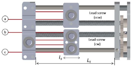
A counterclockwise lead screw is securely fastened to the secondary gear. In contrast, a clockwise lead screw is connected to the additional final gear, as illustrated in Figure A2. These lead screws tension the cable when the main drive rotates clockwise. Conversely, when the main drive rotates counterclockwise, the opposite action occurs.
The cable displacement is directly linked to the slider’s linear movement and the cable’s length, which interacts with the pulley. This unique relationship arises from the looped cable mechanism. In this mechanism, the cable follows two distinct paths, ascending and descending, which are closely tied to the linear motion of the actuating slider. The total linear movement range of the slider (rectangular-shaped lead nut) is denoted by
 $S$
is expressed in Eq. (9) as follows:
 \begin{equation}S= L_{t}-l_{s}\end{equation}
Here,
 $L_{t}$
represents the total length between the motor plate and end support plate, and
 $l_{s}$
represents the length of the rectangular-shaped lead nut measured along its direction of motion (as illustrated in Figure A2). The
 $D_{\textit{stroke}}$
of the cables is given as:
 \begin{equation}D_{\textit{stroke}}= 2S\end{equation}
In Eq. (10),
 $D_{\textit{stroke}}$
represents the total linear displacement of the end-effector cable.
The lead of the slider
 $L_{S}$
can be calculated as:
 \begin{equation}L_{S}= n_{S}p \,(i_{G})\end{equation}
Here in Eq. (11), the gear ratio
 $i_{G}$
is defined as the ratio of the number of teeth on the main drive gear
 $T_{Gm}$
(i.e., motor gear) to the number of teeth on the lead screw gear
 $T_{Gs}$
.
 $n_{S}$
represents the number of threads starts on the screw, and
 $p$
is the pitch of the threaded screw.
The displacement of the cable
 $D_{\textit{cable}}$
per one rotation of the motor can be expressed by Eq. (12) as:
 \begin{equation}D_{\textit{cable}}= 2L_{S}\end{equation}
The linear speed of the end-effector cable
 $V_{\textit{cable}}$
is
 \begin{equation}V_{\textit{cable}}= D_{\textit{cable}}\left(\frac{\omega _{M}}{60}\right)\end{equation}
Here in Eq. (13),
 $\omega _{M}$
denotes the angular velocity of the motor in revolutions per minute (rpm).
The formula for calculating the torque required to raise the load of a lead screw nut (given in Chapter 8 of [Reference Budynas and Nisbett74]) was modified to include the gearing transmission efficiency, representing the relationship between motor dynamics and slider dynamics of the actuator, as follows:
 \begin{equation}\tau _{M}= \frac{F_{S}d_{m} }{2}\left(\frac{L_{S}+\pi fd_{m}\, sec\alpha _{l}}{\pi d_{m}-fL_{S}\, sec\alpha _{l}}\right)\frac{1}{e_{G}}\end{equation}
Here in Eq. (14),
 $\tau _{M}$
is the motor torque,
 $F_{S}$
is the slider force,
 $d_{m}$
is the mean thread diameter,
 $L_{S}$
is the lead of the slider (see Eq. (11)),
 $f$
is the screw friction coefficient,
 $\alpha _{l}$
is the thread geometry parameter, and
 $e_{G}$
is the spur gear efficiency (typically 95–98%). Pulley friction and mass are neglected due to the lightweight design and bearing support. The contribution of the thrust collar bearing friction is also neglected for simplicity, as it is small compared to the screw-and-nut thread friction in the actuator under consideration.
The tension in the cable can be determined from Eq. (15) as follows:
 \begin{equation}F_{\textit{cable}}=\frac{F_{S} }{2n_{B}}\end{equation}
where
 $n_{B}$
is the number of movable pulleys for the cable stroke amplification mechanism (see Figure A1).
This actuator model can be used to guide stroke sizing, gear ratio selection, and motor choice for the underactuated mechanism. The cable displacement relationships (Eqs. (9)–(13)) can be employed to determine the slider stroke required to achieve the desired cable displacement for finger flexion. The torque/tension model (Eqs. (14)–(15)) can be used to estimate the motor torque needed to generate the required cable tension, or conversely, to determine cable tension for a given motor torque. The model can also help verify that the designed actuator provides sufficient displacement and force capability to support the intended tasks.
2.4. Intention-based control system
Given that the intended users of the robotic glove are individuals with weak hands and mild-to-moderate stroke impairment, the affected individuals may be able to move their fingers partially but lack the strength to grasp objects effectively. As such, the controller input commands should be designed to be as simple as possible to accommodate this user group. We implemented a sensor-based force assistance controller, enabling dynamic control of the grasping strength in response to the user’s intent, as detailed in the schematic provided in Figure 7.
The intention-based control system of the SRIG-Exo.

The proposed intention identification method relies on the signals from two types of sensors, utilizing the hybrid sensing technique. The first are bending sensors, which are positioned at the top of the fingers, and the latter are FSRs fixed at the fingertips level (see Figure 2). These FSRs and bend sensors operate with a constant voltage of 3.3–5 V, and variations in current are monitored through an amplifier PCB board. This approach enables the recognition of human intentions by analyzing the wearer’s partial finger movements, fingertip touch, and voluntary grip control. It facilitates assisted grasping with the robotic glove. The microcontroller processes the filtered signal from the FSRs and bend sensors and controls the intelligent motor using a straightforward thresholding technique.
The estimated finger poses can be mathematically analyzed by considering the lead of the rod and the gearing ratio with the motor. Calculating the displacement of the flexor/extensor cable during operation becomes straightforward using Eq. (12) since the angular motion of the motor is known. Finally, the forward kinematics Eqs. (6) and (7) can determine the finger pose.
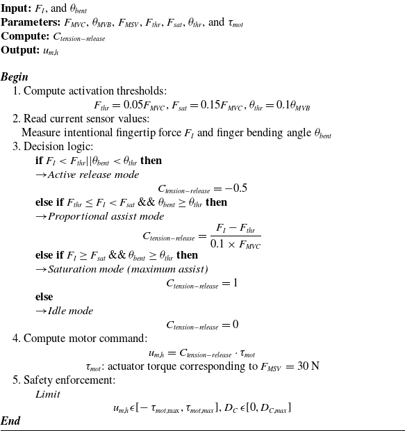
The control algorithm identifies the desired control input for triggering the motor based on the wearer’s estimated finger bending and fingertip force. The algorithm commands assistance force only when the estimated finger bending and fingertip force exceed the predetermined threshold. A study by [Reference Bjorksten and Jonsson75] indicates that the estimated force surpasses 5% of the maximum voluntary contraction (MVC) fingertip force, which the user can sustain for a minimum of 1 h without experiencing substantial fatigue. It is essential to understand that the exact degree of finger bending varies based on factors such as hand anatomy, flexibility, and joint health. However, when people make a fist, the fingers often achieve a significant degree of flexion. In this case, the maximum voluntary bending (MVB) can be in the range of 90° or greater for some individuals. Older adults and individuals with weak muscles have different MVC, MVB, and estimated force surpassing percent values. Therefore, we can modify Eq. (16) by considering suitable values for these variables based on the individual’s capabilities.
The gripping of the different objects required varying bending positions and grip forces. Therefore, the developed algorithm system includes the proportional force control condition where the force of at least one of the fingertips can increase or decrease the motor torque. The bending of fingers is auto-adjusted according to the shape of the grasped object due to the designed cable-loop system in the linear actuator, specifically for the ring and middle fingers. A simple open-loop controller can be used, considering the finger’s MVC fingertip force and MVB values. The device’s exerted fingertip assistance force for improving grasping can be set, for example, 0 to 30 N, following the proportional fingertip force value between 5% and 15% MVC. The intentional force of 5% and 15% of the MVC is selected as the threshold and saturation points, respectively [Reference Park, Heo, Kim and Na63]. A condition: when the estimated fingertip force of the user reaches or exceeds 15% of the MVC fingertip force, the controller would then increase the cable tension corresponding to 30 N, which is the maximum set value (MSV). The RoM for finger bending is determined by the MVB value, allowing fingers to bend from 0° and reach or exceed 90°. However, the shape of the object being grasped can influence the specific degree of finger bending. The relationship between an estimated fingertip force and the actuator control input duty cycle, as described in [Reference Park, Heo, Kim and Na63], is modified to incorporate finger bending for grasping control. The estimated intentional fingertip force
 $F_{I}$
and finger bending angle
 $\theta _{bent}$
are continuously monitored to interpret the user’s motion intention. The assistive motor command
 $u_{m,h}$
is generated proportionally to the normalized cable tension
 $C_{\textit{tension}-\textit{release}}$
, defined as:
 \begin{equation}C_{\textit{tension}-\textit{release}}=\begin{cases} \begin{array}{ll} -0.5, & \begin{array}{l} F_{I}\lt F_{thr} || \theta _{bent}\lt \theta _{thr}\\ \quad (\textit{release}) \end{array}\\ \dfrac{ F_{I}-F_{thr}}{0.1 \times F_{MVC}} , & \begin{array}{l} F_{thr}\leq F_{I}\lt F_{sat}\, \& \&\, \theta _{bent}\geq \theta _{thr}\\ \quad (\textit{proportional}\,\, \textit{assit}) \end{array}\\ 1, & \begin{array}{l} F_{I} \geq F_{sat}\, \& \&\, \theta _{bent}\geq \theta _{thr}\\ (\textit{saturation}\colon \mathit{\max }\,\, \textit{assist}) \end{array} \end{array} \end{cases}\end{equation}
The corresponding actuator command is expressed as:
 \begin{equation}{u_{m,h}}= C_{\textit{tension}-\textit{release}} \cdot\! \tau _{mot}\end{equation}
In Eq. (16),
 $F_{I}$
denotes the estimated intentional fingertip force, and
 $\theta _{bent}$
represents the measured finger bending angle of the wearer. The activation and saturation force thresholds are defined as
 $F_{thr} = 0.05F_{MVC}$
and
 $F_{sat} = 0.15F_{MVC}$
, respectively, where
 $F_{MVC}$
is the MVC fingertip force. The bending activation threshold is set as
 $\theta _{thr} = 0.1\theta _{MVB}$
, where
 $\theta _{MVB}$
denotes the MVB angle of the finger. The actuator torque corresponding to the maximum assistive force (
 $F_{MSV}$
= 30 N) is represented by ⋅
 $\tau _{mot}$
in Eq. (17).
Eq. (16) captures both the tensioning and release behaviors within a unified formulation. When
 $F_{I}$
or
 $\theta _{bent}$
are below their activation thresholds, the controller enters release mode, relaxing the cable tension to allow voluntary finger extension. Once the bending and force exceed their thresholds, the controller transitions to assistive mode, generating proportional cable tension that scales linearly with
 $F_{I}$
until reaching the saturation limit
 $F_{sat}$
. This approach ensures intuitive and user-driven actuation, preventing unintended movements during inactivity while providing smooth, proportional assistance during active grasping. At saturation, the actuator delivers the maximum torque corresponding to
 $F_{MSV}$
.
SRIG-Exo Intention-Based Cable Tension and Release Control

2.4.1. Control system
The SRIG-Exo employs an IBC system architecture that integrates user motion intention with assistance force generation (Figure 7 and Algorithm 1). Motion intention is estimated from two primary sensing pathways: (i) finger bent estimator, which uses flex sensors to detect joint angular displacement; and (ii) fingertip force estimator, which uses pressure sensors to estimate intentional forces during object grasping. These two estimators provide redundant and complementary information on the user’s voluntary action.
The outputs are fused within the assistive glove controller, which generates an assistance force profile tailored to the user’s input. Specifically, once finger bending exceeds a defined threshold MVB and finger force surpasses a scaled proportion of the MVC, the controller issues a proportional motor command. This ensures that assistance is provided only when the user initiates motion, reducing the risk of unintended activation.
The actuator then converts the control signal into cable displacement and actuator torque. The glove exoskeleton applies this torque through tendon-driven transmission, augmenting the user’s finger joint torque. The interface module provides feedback by continuously monitoring estimated joint states (bending and force).
This closed-loop structure ensures that the user remains in control, with the exoskeleton assisting only as needed. The separation of estimators (force and motion) and the use of dual thresholds (MVB and MVC scaling) improve both safety and usability.
2.4.2. SRIG-Exo calibration process
The operation and control algorithm of the proposed SRIG-Exo is straightforward. The algorithm enables the detection of the user’s intention by analyzing the wearer’s partial finger movements, fingertip touch, and voluntary grip control. After donning the device, the wearer can activate it to initialize the algorithm. First, the fingers should be voluntarily straightened as much as possible and held for 5–10 s for the calibration step. Subsequently, the control algorithm initiates the calibration process to record finger bending and fingertip forces as the default values. The device is ready for operation when the calibration is completed. The algorithm receives the amplified signal from the sensors inserted into the glove, filters it, and processes it for the next step. In addition, the sensor monitoring algorithm continuously tracks the movement of the user’s fingers and their contact with objects.
2.4.3. Safety and risk mitigation measures
Several of the design features described earlier also contribute to user safety. To ensure safe operation of the underactuated glove and prevent potential user discomfort or secondary injury resulting from excessive motion or force, protective mechanisms were implemented at both the mechanical and software levels. The actuator incorporates stroke-limiting stoppers on the lead screw and within the detachable cable connector to restrict cable displacement within the natural flexion range of the fingers, while limit switches define the actuator’s end positions. In parallel, software-based position and torque limits constrain the actuator’s motion and output, with the maximum assistive force for grasping limited to approximately 30 N and adjustable according to the user’s capability and task requirements. The Teflon-coated tendons further reduce friction and ensure smooth, stable motion, minimizing wear and tear of the components at contact interfaces. Additionally, an emergency stop button enables the user to interrupt operation immediately in the event of unexpected behavior. These combined safeguards ensure that the SRIG-Exo operates safely under underactuated conditions, preventing excessive flexion, over-tension, or unintended actuation during grasping tasks.
3. Experiments and results discussion
We performed a series of experiments to assess the performance of the robotic glove, linear actuator, and intention-based control strategy. The first experiment involves the robotic glove and the linear actuator, focusing on examining the kinematic relationship between fingers’ flexion–extension and the corresponding displacement and velocity of the cables. The second experiment aims to test the dynamic characteristics of the SRIG-Exo device by measuring the range of grasping forces that can be achieved when the glove is placed on the user’s hand. The third aspect involves evaluating the accuracy of the IBC system by testing the device on both non-disabled and stroke participants for active assistance. Additionally, this experiment evaluates the most common grasps required for performing ADLs using the IBC algorithm.
3.1. Experimental setup
Figure 8 illustrates the experimental setup used to evaluate the motion and force characteristics of the SRIG-Exo. The system comprises the glove worn by the participant, the actuator unit, control electronics, nylon cables with inner Teflon lines serving as Bowden cables for force transmission, and a data acquisition interface connected to a laptop running the control program. Finger motion was recorded to assess the range of motion and actuation response, while force data were collected during assisted grasping tasks.
Experimental setup of the SRIG-Exo worn on a participant’s hand for motion and force characterization. The setup includes: (a) finger motion experiment, (b) experimental setup for grasping force measurement, and (c) representative objects employed in the intention-based object grasping experiments.

Three load cells (HZC-MS2-5 KG, Bengbu Chengying Sensor Co., Ltd., China) were installed at the output of the detachable cable connector to measure the assistance force provided by the actuator (Figure 8). The flex and pressure sensors provided feedback data for motion and force estimation. The sensors were connected to signal conditioning module (4-channel amplifier, Suzhou Leanstar Electronic Technology Co., Ltd., China), which converted the resistance variations of the sensors into corresponding analog voltage signals for the controller’s ADC input.
The setup includes three main evaluation configurations. Figure 8(a) illustrates the finger motion experiment used to record joint flexion–extension movements while the glove followed predefined motion patterns. This setup was employed to analyze the correspondence between the glove’s tendon displacement and the resulting finger joint angles measured by the flex sensors.
Figure 8(b) shows the grasping force measurement (GFM) setup, designed to evaluate the grasping forces exerted by the glove. The GFM model comprises a custom-designed cylindrical fixture, 70 mm in diameter, embedded with three load cells (HZC-MS2-5 KG) that are aligned to measure the forces exerted by individual fingers during grasping experiments.
Figure 8(c) illustrates representative objects used during the grasping experiments. These objects were selected to reflect common daily-use items and were employed in repeated grasping trials to evaluate grasping adaptability and the effectiveness of the intention-based control.
All sensor signals were acquired via microcontrollers and transmitted to a laptop for analysis of the SRIG-Exo’s kinematic and dynamic performance (see results in Sections 3.2 and 3.3). In addition, intentional control-based grasping experiments were conducted to validate the control algorithm and evaluate the glove’s capability to assist in the grasping of objects with different shapes (results are detailed in Section 3.4). Descriptive statistics were used to summarize system performance. Finger flexion results were averaged across repeated trials, grasping force was analyzed over time, grasping performance with various objects and intention-based control accuracy were summarized across participants, and donning/doffing times and comfort ratings were reported as mean values.
3.2. Fingers motion experiment
To simplify our analysis, we assume the fingers’ MCP, PIP, and DIP joints are a single DoF body for the ring finger, middle finger, and thumb, respectively. This allows us to rationalize our approach and focus on essential aspects. Furthermore, this approach allows wearers to assume more natural and comfortable postures. The utilization of bend sensors along the upper surface of the fingers enhances the SRIG-Exo system by providing valuable feedback during the flexion and extension movements of the fingers. The robotic glove was worn on the healthy hand without introducing any additional load (see Figure 8). The desired motion is provided to the actuator, and simultaneous measurements of kinematic values for both the actuator and hand are recorded during hand closing and opening tasks, as illustrated in Figure 9. Here, finger flexion is an active movement, whereas extension is a passive and voluntary movement.
Fingers flexion–extension: (a) middle finger (MF) and ring finger (RF), and (b) thumb.

In the control system, the motion is conveyed regarding cable displacement, representing the joint configuration with sinusoidal motion. The initial cable displacement
 $D_{C}$
for the fingers is set at 0, serving as the default position. The motion for the final cable displacement is programmed as [0, 70, 0, 70, 0] mm, with a peak cable velocity of 20 mm/s for the fingers. In comparison, the thumb is synchronized via a synergy ratio of the thumb gear connected to the fingers’ gear. Note that the physical limits of the finger joints vary among individuals. The designed linear actuator can mechanically displace the cable up to a maximum of approximately 10 mm.
The trajectory was executed within the range of 0 to 70 mm (adhering to predefined waypoints) to facilitate motion analysis of the SRIG-Exo model. We observed precise control and smooth motion at the actuator side. The finger joint movements of the hand displayed a smooth sinusoidal oscillation pattern, with average values ranging from approximately 0° to 138° for the ring finger, 0° to 130° for the middle finger, and 0° to 56° for the thumb joints, as depicted in Figure 9(a) and (b). The glove-side finger and thumb joint motions show diminished smoothness and accuracy relative to the actuator’s input motion. This discrepancy arises from several factors, including the glove’s soft material, the complexity of cable routing within the glove, and the glove’s adaptability to the wearer’s hand.
3.3. Grasping force measurement experiment
Grasping experiments using the device’s intention recognition control system were conducted to evaluate its power grasping capability and to analyze the relationship between grasping force and user-intended force (Figure 8(b)). The grasping forces produced by the glove were roughly aimed at achieving 10 N, 20 N, and a maximum of 30 N, utilizing the developed IBC algorithm.
In this grasping experiment, the force assistance threshold values were set at 2 N (5% MVC) and saturation forces at 6 N (15% MVC) for healthy subjects, assuming the MVC force of 40 N, and the maximum possible assistance force
 $F_{MSV}$
was set to 30 N. The SRIG-Exo’s glove was worn on the healthy hand, and the experiments were performed. The experiment began when the fingers were fully extended, and the user attempted to grasp the GFM model.
In the Bowden cable system, changing the cable configuration in space can significantly impact force transmission efficiency [Reference M., Letier, Schiele and Avraam76]. Therefore, the location of the glove exoskeleton and the hardware box were maintained to avoid further influence of cable bending. Notably, this research does not examine the influence of cable bending and friction parameters on the proposed model. Additionally, the effect of friction forces between the cables and their routing paths within the glove at different finger bending positions for grasping was not investigated in this study.
The participant was instructed to increase the intentional force near the aimed value and hold that force for 10–15 s. The dynamic experimental results for the grasping force under different intentional forces are illustrated in Figure 10. The intentional force exceeded the force assistance threshold in the initial phase during the 0–2 s time period as shown in Figure 10(a). In this first phase, a rapid increase in the intentional forces can be observed for
 $F_{I1}$
,
 $F_{I2}$
, and
 $F_{I3}$
to approximately 3.53 N, 4.66 N, and 6.43 N (exceeding the saturation point), respectively. The actual deployment of assistance forces occurred about 2–3 s after the intentional force surpassed the threshold. This delay arose from the tendon-driven glove design, where flexion cables are kept slightly loose to allow easy donning and natural hand movement. Once the threshold was exceeded, the servo first tightened the cables, after which the force was transmitted to produce finger flexion.
Grasping force measurement results: (a) Trial 1, where
 $F_{I1}$
,
 $F_{I2}$
, and
 $F_{I3}$
represent the estimated intentional forces, while
 $F_{G1}$
,
 $F_{G2}$
, and
 $F_{G3}$
denote the corresponding grasping forces (i.e., the forces generated by the actuator, excluding the human’s intentional input), (b) Average values across the three trials.

In the second phase, the grasping forces
 $F_{G1}$
,
 $F_{G2}$
, and
 $F_{G3}$
closely followed the intentional forces, reflecting the user’s active contribution to augment grasp strength. This phase is critical, as it directly evaluates the glove’s ability to enhance the user’s grasping performance. During this period, the mean intentional forces
 $F_{I1}$
,
 $F_{I2}$
, and
 $F_{I3}$
were approximately 3.55 N, 4.71 N, and 6.55 N, respectively, while the corresponding mean grasping forces were 9.75 N, 19.81 N, and 29.35 N, as shown in Figure 10(a). During the release phase, the synchronized decrease in grasping force in response to intentional reduction confirms the glove’s ability to smoothly disengage, enabling finger extension while maintaining user-driven control.
Figure 10(b) summarizes these results as a bar graph, where each bar represents the mean intentional and grasping forces for a given trial, and the final bar indicates the overall average. To evaluate the stability of the assisted grasp, the mean and standard deviation (SD) of the grasping forces were calculated across the three trials. The mean grasping forces for
 $F_{G1}$
,
 $F_{G2}$
, and
 $F_{G3}$
were 9.89 ± 0.29 N, 20.45 ± 0.7 N, and 29.68 ± 1.21 N, respectively. The close agreement between measured and target forces, together with low SDs, indicates that the device provides consistent and reliable assistance across repeated trials.
The dynamic correlation between intentional and grasping forces informs the optimal input required within the control system to achieve the desired grasping strength. Overall, these results demonstrate that the SRIG-Exo glove can deliver grasping forces of up to approximately 30 N while effectively modulating assistance according to user intent.
In this experiment, the participant was instructed and practiced multiple times to be able to maintain and apply the near-correct intentional force. This intentional force should be close to the aimed target to achieve the grasping force near the desired values. Therefore, the measured results could be influenced by the individual’s skills and training capabilities. However, this issue should not significantly affect the device’s performance during grasp tasks in practical applications because the grasping force can be maintained straightforwardly due to the proportional relationship of the grasping force to the user’s intent. Furthermore, increasing the threshold and saturation values can enhance the operating range and sensitivity in the control system, resulting in better control of the SRIG-Exo device. This increment can help improve the stability and ease of operation of the device by utilizing the IBC algorithm.
3.4. Intention-based object grasping experiments
The experimental setup illustrated in Figure 8 was used to evaluate the grasping performance of the SRIG-Exo and to assess the effectiveness of the multimodal IBC algorithm. The trials aimed to verify whether the system could accurately interpret the wearer’s motion intention and generate appropriate assistive actions for object grasping.
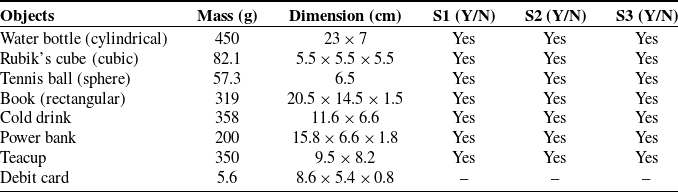
Three healthy participants (S1–S3; all male; age: 31.2 ± 3.4 years; weight: 67.2 ± 8.5 kg; height: 171.6 ± 7.3 cm) voluntarily took part in the study, each performing three consecutive trials involving a set of daily-use objects with varying shapes, sizes, and weights (see Table II). During each trial, the subjects wore the SRIG-Exo glove and were instructed to grasp and release the presented objects, while the hybrid sensing system continuously monitored the fingertip pressure and finger bending signals. The parameter values such as
 $F_{thr}$
,
 $F_{sat}$
,
 $F_{MVC}$
,
 $F_{MSV}$
,
 $\theta _{thr}$
, and
 $\theta _{MVB}$
for all participants were kept consistent with those defined in Section 3.3.
Objects used during the grasping experiment and the accuracy of the IBC algorithm for healthy subjects.

The grasping outcomes were evaluated by recording whether the object was successfully grasped and held under intention-based assistance (Figure 11). The resulting classification accuracy of the IBC model is summarized in Table II. A successful grasp was labeled as “Yes” when the participant was able to complete three consecutive grasps of the same object without failure; otherwise, it was labeled as “No.” These results provided insight into the model’s responsiveness and reliability in recognizing motion intentions and generating appropriate assistive forces.
The SRIG-Exo is being worn while grasping test objects, with the voluntary grasping of the debit card being performed without assistance from the glove: (a) water bottle, (b) Rubik’s cube, (c) tennis ball, (d) book, (e) cold drink, (f) power bank, (g) teacup, and (h) debit card.

The system did not assist with card grasping, and the user made an entirely voluntary motion. While grasping other objects listed in Table II, the users were well informed about the position of the tactile sensors. This technique helped the wearers efficiently use the device by ensuring FSR sensors were in contact with the object during each trial. However, maintaining accuracy may be more challenging for other users than we achieved. Therefore, Section 4 outlines suggestions for future work, focusing on enhancing the performance of the IBC algorithm to achieve optimized outcomes across a diverse range of users.
In this experiment, the middle finger and ring finger exhibited higher flexion (up to 121° and 133°, respectively) when grasping larger objects such as the power bank, whereas most other objects required joint angles below 95°, except for the Rubik’s cube and tennis ball (see Figure 12). The thumb showed comparatively lower angular values (25–57°) across all tasks, consistent with its supporting role in stabilizing the grip according to the first-hand synergy relationship with the fingers.
Joint angles of the MF, RF, and thumb fingers measured during the grasping of various objects shown in Figure 11 using the SRIG-Exo. Each object corresponds to three color-coded bars representing the respective finger, while the solid black line indicates the measured grasp force. (*: it represents voluntary grasping).

The grasp force, indicated by the black line, also varied with object type, ranging from 3.4 N for the debit card (which was voluntarily grasped without SRIG-Exo assistance) to 13.6 N for the water bottle. Higher grasp forces (within 9–14 N) were observed for objects weighing more than 300 g, such as the book, cold drink can, teacup, and water bottle, while lighter objects under 100 g, such as the tennis ball and Rubik’s cube, required lower forces below 6 N. This trend indicates that the SRIG-Exo provided sufficient assistance to achieve stable grasping while maintaining user comfort. These results confirm that the SRIG-Exo can modulate both joint motion and output force according to the grasping requirement, demonstrating its capability to provide adaptive assistance under intention-based control.
3.4.1. Early clinical feasibility test
In addition to the healthy-subject trials, a preliminary clinical evaluation was performed to assess the SRIG-Exo’s feasibility in assisting grasping tasks for individuals with impaired hand function. Four post-stroke participants (P1–P4) with mild-to-moderate hand impairment were recruited with institutional ethical approval, and written informed consent was obtained from all participants. All participants exhibited grade 2–3 finger muscle strength (assessed by manual muscle testing, MMT), with preserved finger flexion but insufficient functional grasp strength. The tests focused on evaluating the system’s ability to support finger flexion and detect user intention during a simple water bottle grasping task (experiments are shown in Figure 13). Each participant performed multiple grasp–release trials while wearing the SRIG-Exo, and qualitative feedback on feasibility, comfort, ease of donning and doffing, and user acceptance was collected.
Stroke patients wearing the SRIG-Exo device during experimental trials: (a) P1 (male, 62 years), (b) P2 (male, 65 years), (c) P3 (female, 59 years), and (d) P4 (female, 61 years).

To accommodate weakened grip strength, the threshold and saturation forces were set to 1.5 N and 4.5 N, respectively, while maintaining the same
 $F_{MSV}$
= 30 N as in the healthy-subject trials. Motion intention was recognized when both finger bending and fingertip pressure exceeded their respective thresholds, triggering proportional assistance through the IBC algorithm.
All participants successfully grasped and released the bottle with visible assistance from the SRIG-Exo. The glove was reported to be moderately easy to wear and remove, with an average donning time under 2.5 min. Participants rated comfort at an average of 6.8 out of 10, highlighting the glove’s lightweight, soft, and ergonomic design.
Overall, the patients appeared relaxed and confident during assisted grasping, confirming the system’s feasibility for safe and comfortable early rehabilitation use. Future studies will include quantitative analyses of motion and force following further device optimization.
3.5. Discussion and comparative analysis
The kinematic experiments demonstrated that finger trajectories closely followed the actuator input, with flexion angles for the ring, middle, and thumb joints reaching approximately 138°, 130°, and 56°, respectively, indicating smooth and accurate motion. Dynamic experiments confirmed that the actuator could generate a maximum assistive force of around 30 N, sufficient for both rehabilitation and daily activity tasks. Subsequent object grasping trials verified the glove’s stability and adaptability when handling objects of varying shapes, sizes, and weights. The multimodal intention-based control system effectively interpreted user intent, providing proportional assistance and enabling reliable and smooth grasping. Preliminary clinical feedback from stroke patients suggested that the glove was comfortable, easy to don and doff, and functionally feasible for assisting grasping tasks, supporting its potential for early rehabilitation applications.
Overall, the experimental results confirmed that all key design requirements defined in Table I were met. The SRIG-Exo prototype achieved a glove weight of 140 g and a total system weight of 0.98 kg, satisfying the portability targets. The compact underactuated actuator successfully drove three fingers using a single motor, automatically adapting to different object shapes, and is also capable of maintaining stable grasping without continuous power, with a maximum cable stroke of 10 cm. The finger range of motion provided adequate functional flexion for smooth motion and user comfort (Section 3.2). Grasping force tests demonstrated that the device could deliver a maximum assistive force of approximately 30 N, meeting the requirements for most daily activities (Section 3.3). The multimodal intention-based control provided smooth, user-driven proportional assistance in accordance with the defined activation and saturation thresholds (Section 3.4). Donning and doffing were completed in approximately 2.5 min, with an average comfort rating of 6.8/10, indicating good usability and user experience (Section 3.4.1). Collectively, these results validate that the SRIG-Exo prototype satisfies the design requirements outlined in Table I, confirming the effectiveness of its mechanical design, control strategy, and overall suitability for rehabilitation and assistive applications.
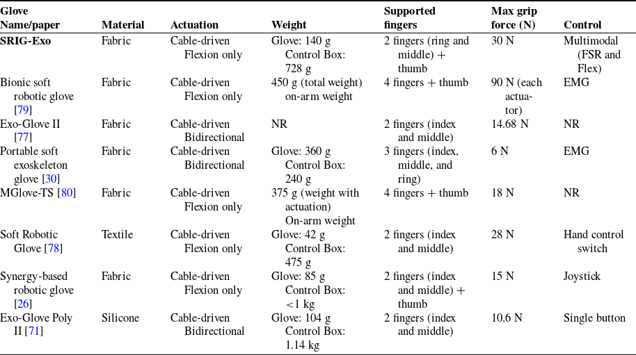
Table III compares the proposed SRIG-Exo with representative cable-driven glove devices. Unlike most existing gloves that assist only two fingers, such as the Exo-Glove II [Reference Kim, Jeong and Cho77], Soft Robotic Glove [Reference Thimabut, Terachinda and Kitisomprayoonkul78], and Exo-Glove Poly II [Reference Kang, Choi, Lee and Cho71], SRIG-Exo supports three fingers (ring, middle, and thumb) to enable natural grasping assistance. The glove is lightweight (140 g), comparable to or lighter than systems such as the Portable Soft Exoskeleton Glove [Reference Ismail, Ariyanto, Setiawan, Hidayat Paryanto and Nuswantara30], and lighter than other devices whose entire weight rests on the user’s arm, including the Bionic soft robotic glove [Reference Zhang, Zhu, Bao, Li, Zhang, Wang, Wu, Zheng and Li79] (450 g) and the MGlove-TS [Reference Dragusanu, Troisi, Suthar, Hussain, Prattichizzo and Malvezzi80] (375 g). By placing the control box off-arm, SRIG-Exo reduces user fatigue during prolonged use. Although some gloves are lighter (e.g., [Reference Alicea, Xiloyannis, Chiaradia, Barsotti, Frisoli and Masia26, Reference Kang, Choi, Lee and Cho71, Reference Thimabut, Terachinda and Kitisomprayoonkul78]), SRIG-Exo incorporates a detachable cable connector (30 g), multi-sensors with wiring and onboard signal-conditioning circuits, slightly increasing glove-side weight.
Comparative summary of SRIG-Exo and existing cable-driven glove devices.

SRIG-Exo utilizes a lead-screw-driven cable-loop mechanism, enabling a single motor to actuate multiple fingers through stroke amplification, thereby reducing the actuator count and system weight. With a maximum grip force of 30 N, SRIG-Exo provides higher grasping capability than most devices listed, except the Bionic Soft Robotic Glove [Reference Zhang, Zhu, Bao, Li, Zhang, Wang, Wu, Zheng and Li79] (90 N per motor), while maintaining safety and efficiency for daily and rehabilitative use. Its multimodal control, combining bend and pressure sensors, provides intention-based proportional assistance without dependence on EMG signals, benefiting users with weak or unreliable muscle signals. This intention-based control also offers more natural and engaging rehabilitation compared to devices relying on manual triggers, such as Soft Robotic Glove, Synergy-based robotic glove, and Exo-Glove Poly II. Overall, SRIG-Exo achieves a balanced compromise between weight, control simplicity, and grasp performance, demonstrating potential for home-based rehabilitation.
The glove design emphasizes comfort and modularity through optimized tendon routing and a detachable cable connector mechanism, allowing easy replacement and donning/doffing; these features can enhance usability in home-based rehabilitation settings. Compared to prior robotic glove designs that rely on multi-motor or spool-based rotary actuation, the SRIG-Exo employs a compact lead-screw-driven slider with a stroke amplification loop, allowing one motor to drive multiple fingers while providing mechanical self-locking without the need for active clutches. This configuration achieves a balance between compactness, efficiency, and stable grasping performance. Furthermore, the integrated multimodal IBC framework, combining bend and fingertip pressure sensing, enables proportional, user-driven assistance suitable for individuals with weak or partial hand motion. Overall, these combined features demonstrate that the SRIG-Exo effectively integrates mechanical simplicity, ergonomic design, and intuitive control, distinguishing it from conventional single-sensor or multi-actuator glove systems while maintaining suitability for daily and rehabilitation use.
The demand for hand exoskeletons is growing, driven by advances in biomechanics, human–robot interaction, actuators, sensors, rehabilitation strategies, and control systems for restoring hand function after stroke and other conditions. The SRIG-Exo module developed in this research is lightweight, enhancing wearability and ease of use for patients. The final SRIG-Exo glove’s weight is 140 g, which is less than 50% of the weight based on the user intent-modality glove devices found in the review paper [Reference Chu and Patterson22]. The lightweight, cost-effective, and untethered SRIG-Exo device can offer a feasible approach to improving the accessibility of home-based rehabilitation and assistance with ADLs. The proposed multimodal sensing strategy may enhance effectiveness for rehabilitation, supporting finger function recovery and routine task performance.
4. Limitations and future work
The current SRIG-Exo prototype integrates a limited number of FSR sensors positioned only at the fingertips, which may constrain the resolution of the user-intent detection algorithm. Future versions will incorporate additional sensors along the finger phalanges to capture contact patterns and improve grasp recognition accuracy. The present glove was fabricated using a custom, manually assembled process that affects mechanical consistency and sensor placement accuracy. Future designs will adopt professional, tailor-made fabrication techniques to enable precise sensor integration and optimized force transmission through the soft structure.
The employed linear actuator provides limited cable displacement speed compared with natural finger motion in ADLs. Further improvements in actuator dynamics are planned to achieve higher motion speeds and smoother grasp assistance. Additionally, cable friction arising from varying bending angles requires systematic analysis and compensation in future iterations.
To strengthen the intention-based control framework, integration of high-quality surface EMG sensors is proposed for detailed evaluation of the relationship between muscle activation and grip force, complementing the multimodal sensing system.
Finally, current experimental validation has been limited to three healthy subjects and four stroke patients. Expanded clinical studies with a larger cohort will be conducted after implementing the above improvements. Overall, these developments aim to advance the SRIG-Exo toward a lightweight, wearable, and intuitively controlled rehabilitation device suitable for at-home use.
5. Conclusion
Loss of grasping force and dexterity can significantly affect an individual’s quality of life. However, most existing devices designed to assist with grasping lack the combination of intention-based control and suitability for unsupervised, at-home use. In this paper, we developed a soft glove device employing a tendon-driven mechanism for finger movement and grasping force assistance during ADLs and rehabilitation. We introduced a model-based design featuring a tendon-driving unit for a soft wearable glove. In the designed linear actuation system, a single motor assists the ring finger, middle finger, and thumb movements and grasping strength. The actuation system incorporates a locking mechanism, enabling it to maintain a static posture with minimal power consumption. A stroke amplification mechanism is adopted to increase cable velocity and reduce actuator length, prioritizing a lightweight and low-power-consuming actuator. The cable detachable connector design is implemented to facilitate easy connection of the soft glove with the actuator, thereby enabling convenient donning and doffing of the glove. The weight of the soft glove is just 140 g, including the detachable connector part and PCB board of sensors, while the backpack weighs 725 g. The portability and wearability of the SRIG-Exo device can allow users to conduct rehabilitation training both at home and outdoors, offering flexibility and convenience.
The capability to intentionally control the hand exoskeleton is critical for enhancing human rehabilitation and facilitating ease in performing ADLs. This soft glove is integrated with an active control strategy where the actuator is controlled based on the user’s estimated finger movements and grip force. The device may assist the users in keeping them engaged during active rehabilitation, potentially aiding in fast recovery and providing convenience in task performance. Overall, the experimental results indicate satisfactory performance of this prototype device, which suggests that the device could be helpful for performing ADLs and rehabilitation training.
Financial support
This research was funded by Nanjing HUAGU Technologies Co. Ltd, China (Grant Number: 8502008413).
Competing interest
The authors declare that no conflicts of interest exist.
Ethical approval
All experimental procedures involving human participants were approved by the Ethics Committee of the First Affiliated Hospital of Shenzhen University (Approval No. 2024SYY-052). Written informed consent was obtained from all participants prior to the study.
Author contribution
Danaish: conceptualization, methodology, formal analysis, investigation, writing – original draft, and writing – review and editing. Professor Han Liang: methodology, writing – review, and supervision. Professor Gelin Xu and Dr. Xu Zongliang: resources and writing – review. Mohammad Abbas Baig, Yangzhen Gao, and GuanCheng Dong: data curation and resources.
Appendix A. Linear Actuator-Based Under-Actuation Design
The CAD design of the linear actuator-based under-actuation mechanism is shown below.
The linear actuator: (a) flexible steel cable, (b) cable fixture, (c) bearing, (d) shaft, (e) cable tensioning slider, (f) support plate, (g) motor plate, (h) limit sensor, (i) motor, (j) support bearing, (k) threaded rod (multi-start), (l) rectangular-shaped lead nut, (m) cables terminal support, (n) linear guide, (o) end support plate, and (p) gearings.

Schematic view of the stroke amplification mechanism: end-effector cables a, b, and c correspond to the thumb, middle, and ring finger cables, respectively.