1. Introduction
Inertial interactions with solid boundaries or suspended particles have pronounced and well-known effects on fluid flow, from the formation of wakes and recirculating zones behind obstacles (Taneda Reference Taneda1956a
,Reference Taneda
b
) to the generation of complex flow patterns around immersed objects (Subramanian & Koch Reference Subramanian and Koch2006). Consideration of the interaction of inertial and viscous effects is central to our understanding of fluid mechanics and has been extremely well studied. However, when suspensions are considered there is much less known, with the best-known phenomenon being that observed initially by Segré & Silberberg (Reference Segré and Silberberg1962a
,Reference Segré and Silberberg
b
): in pressure-driven tube flow of a dilute suspension, particles small relative to the tube radius
 $R$
migrate towards a preferred annular ring about
 $0.6R$
from the centreline at small tube-scale Reynolds number. This basic phenomenon has been shown to extend to solid fractions of
 ${\it\phi}\approx 0.2$
(Han et al.
Reference Han, Kim, Kim and Lee1999), and up to values of
 $Re$
approaching the transition to intermittent turbulence with a stable radial equilibrium approaching the wall, as predicted by theory (Asmolov Reference Asmolov1999), but with a second equilibrium at smaller radius (Matas, Morris & Guazzelli Reference Matas, Morris and Guazzelli2004; Shao, Yu & Sun Reference Shao, Yu and Sun2008). Inertia also alters the rheological (Kulkarni & Morris Reference Kulkarni and Morris2008; Yeo & Maxey Reference Yeo and Maxey2013; Haddadi & Morris Reference Haddadi and Morris2014) and heat transfer properties (Subramanian & Koch Reference Subramanian and Koch2006) of particle-laden fluids. In confined geometries, such as microfluidic devices, inertia has been employed to order suspended particles, in what is called inertial self-assembly (Humphry et al.
Reference Humphry, Kulkarni, Weitz, Morris and Stone2010). The ‘centrifuge-on-a-chip’ device utilizes the vortices formed in cavities of a microchannel to separate cancerous cells from blood flow (Mach et al.
Reference Mach, Jae, Arshi, Soojung and Di Carlo2011; Sollier et al.
Reference Sollier, Go, Che, Gossett, Bryne, Weaver, Kummer, Retting, Goldman, Nickols, Mccloskey, Kulkarni and Di Carlo2013), and the concepts developed in the present work are relevant to this application.
In this work, we study a rather different inertial effect, considering particle-laden flow in and around the wake formed by flow over a cylindrical obstacle. We have experimentally observed that in flow of a dilute suspension over a cylinder a depleted region forms behind the obstacle. The flow of a simple fluid around a cylinder is, of course, a well-known fluid mechanical problem often used as a benchmark for numerical methods. For Reynolds number defined as
 $Re={\bar{U}}D/{\it\nu}$
, where
 ${\bar{U}}$
is the average axial velocity,
 $D$
is the diameter of the cylinder and
 ${\it\nu}$
is the fluid kinematic viscosity, at
 $Re=O(10)$
a closed-streamline zone, or recirculating wake, forms behind the cylinder. The size of the recirculating zone increases with increasing
 $Re$
, until the steady-state wake becomes unstable, eventually shedding vortices from alternating sides of the cylinder (Batchelor Reference Batchelor1967).
An important point for our work is that the Reynolds number is kept below the onset of unsteadiness. As opposed to the unsteady wake, which results in the formation of von Kármán vortex streets and a significant mass exchange between the wake and free stream, the recirculating wake resulting from bulk inertia is isolated from the remainder of the flow, i.e. its boundary represents a separatrix. We study the interaction between neutrally buoyant particles and recirculating wakes in a range of
 $Re$
which yields a steady wake for pure fluid flow. Thus, there is a distinction between the present work and studies of suspension flow past obstacles in the unsteady wake regime (Tang et al.
Reference Tang, Wen, Yang, Crowe and Troutt1992; Burns, Davis & Moore Reference Burns, Davis and Moore1999; Yang et al.
Reference Yang, Crowe, Chung and Troutt2000) or low-
 $Re$
flow of particulate suspensions over arrays of obstacles, intended for size-based separation. At the low
 $Re$
of the latter studies, recirculating zones do not form behind the obstacles. We have experimentally observed that in flow of a dilute suspension at Reynolds numbers yielding a steady wake, a particle-free zone forms in the recirculation behind the obstacle. To elucidate this observation, we perform numerical simulations by a lattice-Boltzmann method (LBM) for suspensions (Ladd Reference Ladd1994a
,Reference Ladd
b
; Aidun, Lu & Ding Reference Aidun, Lu and Ding1998), considering a sequence of problems from one-particle motion up to a many-body suspension. The work reveals that the mechanism for depletion involves a tendency of individual particles to migrate towards a limit-cycle trajectory near the outer boundary of the closed-streamline region, combined with velocity fluctuations which cause escape from the recirculating wake.
The work begins in § 2 with a summary of the LB technique. In § 3, we explain the experimental procedure and the observations of the depleted zone behind the obstacle. The results of the numerical investigation are given in § 4.
2. Computational method and parameters
We consider flow of a suspension past a cylinder. Here, we outline the numerical method to be used in the study, with more details available in Haddadi & Morris (Reference Haddadi and Morris2014). The motivating problem is discussed in the following section, which is devoted to physical experiments. The fluid phase governing equations in non-dimensional form are
 $$\begin{eqnarray}\displaystyle & \boldsymbol{{\rm\nabla}}\boldsymbol{\cdot }\boldsymbol{u}=0, & \displaystyle\end{eqnarray}$$
 $$\begin{eqnarray}\displaystyle & \displaystyle Re\left(\frac{\partial \boldsymbol{u}}{\partial t}+\boldsymbol{u}\boldsymbol{\cdot }\boldsymbol{{\rm\nabla}}\boldsymbol{u}\right)=-\boldsymbol{{\rm\nabla}}p+{\rm\nabla}^{2}\boldsymbol{u}, & \displaystyle\end{eqnarray}$$
 $D$
, velocity
 $\boldsymbol{u}$
by the average axial velocity of the fluid
 ${\bar{U}}$
, time
 $t$
by
 $D/{\bar{U}}$
and pressure
 $p$
by
 ${\it\mu}{\bar{U}}/D$
. The LBM utilized here for simulation of the particle-laden flow was developed by Ladd (Reference Ladd1994a
,Reference Ladd
b
), with improvements for moving particles by Aidun et al. (Reference Aidun, Lu and Ding1998). The LBM for suspensions is based on solving the Boltzmann equation for the fluid phase, combined with Newtonian dynamics for the solid particles, i.e. the translational (
 $\boldsymbol{V}_{i}$
) and rotational (
 ${\it\bf\Omega}_{i}$
) velocities of particles are governed by
 $$\begin{eqnarray}\displaystyle & \displaystyle m_{i}\frac{\text{d}\boldsymbol{V}_{i}}{\text{d}t}=\boldsymbol{F}_{i}, & \displaystyle\end{eqnarray}$$
 $$\begin{eqnarray}\displaystyle & \displaystyle I_{i}\frac{\text{d}{\it\bf\Omega}_{i}}{\text{d}t}=\boldsymbol{T}_{i}, & \displaystyle\end{eqnarray}$$
 $\boldsymbol{F}_{i}$
and
 $\boldsymbol{T}_{i}$
are, respectively, the force and torque on particle
 $i$
, of mass
 $m_{i}$
and moment of inertia
 $I_{i}$
.
In the LBM, the fluid is composed of fictitious ‘LB particles’ moving on fixed lattice directions. A
 $D3Q19$
lattice, meaning a three-dimensional lattice with
 $19$
velocity directions, including the one for the case of no motion, was used here. The time-dependent population density of LB particles is quantified by a one-particle distribution function at each lattice site,
 $n_{i}(\boldsymbol{r},t)$
. The mass density of the fluid
 ${\it\rho}$
, momentum
 $\boldsymbol{j}={\it\rho}\boldsymbol{u}$
and momentum flux
 ${\it\bf\Pi}$
are defined by taking moments of the distribution function
 $$\begin{eqnarray}{\it\rho}=\mathop{\sum }\limits_{i}n_{i},\quad \boldsymbol{j}=\mathop{\sum }\limits_{i}n_{i}\boldsymbol{c}_{i},\quad {\it\bf\Pi}=\mathop{\sum }\limits_{i}n_{i}\boldsymbol{c}_{i}\boldsymbol{c}_{i}.\end{eqnarray}$$
The Boltzmann equation describes the evolution of
 $n_{i}(\boldsymbol{r},t)$
 $$\begin{eqnarray}n_{i}(\boldsymbol{r}+\boldsymbol{c}_{i}{\rm\Delta}t,t+{\rm\Delta}t)=n_{i}(\boldsymbol{r},t)+\mathop{\sum }\limits_{j}{\it\bf\Omega}_{ij}(n_{i}-n_{i}^{eq}),\end{eqnarray}$$
where
 ${\it\bf\Omega}_{ij}$
is the linearized collision operator, which determines the change of
 $n_{i}$
due to molecular collisions at each time step
 ${\rm\Delta}t$
, and
 $n_{i}^{eq}$
is the equilibrium distribution function. By using a Maxwell–Boltzmann distribution function, the Navier–Stokes equations are recovered from the Boltzmann equation.
The solid–liquid boundary conditions are implemented by using the ‘link-bounce back’ method. The actual boundaries of the particle cut the links between lattice nodes and the boundary node is placed half-way along the links. The LB particles streaming on the links interact with the boundary nodes, so that
 $n_{i}$
of the fluid just outside of the particle is modified in such a way that the fluid velocity is matched to the local solid velocity. Following Aidun et al. (Reference Aidun, Lu and Ding1998), the fluid is removed from the interior of the particle. A fuller description is provided in the original articles and by Haddadi & Morris (Reference Haddadi and Morris2014).
The total force and torque applied on each particle are calculated by summing over all boundary nodes of the particle as
 $$\begin{eqnarray}\boldsymbol{F}=\mathop{\sum }\limits_{\boldsymbol{r}_{b}}\boldsymbol{f}(\boldsymbol{r}_{b}),\quad \boldsymbol{T}=\mathop{\sum }\limits_{\boldsymbol{r}_{b}}(\boldsymbol{r}_{b}-\boldsymbol{R})\times \boldsymbol{f}(\boldsymbol{r}_{b}),\end{eqnarray}$$
and the particle positions and velocities are then updated, knowing the force and torque along with mass and moment of inertia. For surface separations below one lattice unit, the method is insufficient to resolve the flow in the thin gap, such that a lubrication correction should be implemented, with the form proposed by Nguyen & Ladd (Reference Nguyen and Ladd2002) used here as detailed in Haddadi & Morris (Reference Haddadi and Morris2014).
For simulation of the particle-laden flow over a circular cylinder, we use a rectangular computational box with periodic boundary conditions in the
 $x$
,
 $y$
and
 $z$
directions. The mean flow is in the
 $x$
direction, with the circular cross-section of the cylinder on the
 $xy$
plane. To study the dynamics of particles released in the wake region and in the absence of particles in the free stream, the computational box is
 $256\times 128\times 129$
lattice units in the
 $x,y$
and
 $z$
directions, respectively. For simulation of suspension flow past the obstacle at finite volume fractions, a
 $512\times 128\times 129$
box is utilized to minimize the effect of periodic boundary conditions in the flow direction. For both computational domains, we verify the size of the wake at any specified
 $Re$
using the experimental wake size as a function of
 $Re$
(Taneda Reference Taneda1956b
). The diameter of the post is
 $64$
lattice units. The size ratio of the particle with respect to the post is controlled by the size of the particle, and is defined as
 ${\it\delta}=d/D$
, where
 $d$
is the particle diameter. The diameters of particles studied here are
 $5.84$
,
 $10.08$
and
 $12.9$
lattice units. The box is populated by different numbers of particles, depending on the solid fraction: for
 ${\it\phi}=0.04,0.06$
and
 $0.08$
, there are
 $3401$
,
 $4599$
and
 $5905$
small or
 $661$
,
 $895$
and
 $1226$
large particles, respectively.
3. Experiments
The suspension flow experiments were conducted in a microchannel. Polydimethylsiloxane (PDMS) microchannels are fabricated using standard soft lithography techniques. PDMS elastomer (Sylgard 184, Dow Corning) is prepared by mixing and degassing a 10:1 ratio of silicone base to curing agent. The mixture is poured over a microchannel mould and cured at
 $65\,^{\circ }\text{C}$
. We fabricate moulds using high-resolution transparency masks and SU8 negative tone photoresist (Microchem) on a silicon wafer. The height and the width of the fabricated microchannels are measured to be
 $60\ {\rm\mu}\text{m}$
and
 $465\ {\rm\mu}\text{m}$
, respectively. The length of the microchannel is 10 mm, with the cylinder obstacle located midway between the inlet and the exit ports. Flow is driven by a syringe pump (Harvard Apparatus PHD 2000) using a gas-tight glass syringe (Hamilton). We use an upright microscope (Eclipse E400 POL) with backlighting for visualization, with images captured by a high-speed digital camera (Photron Fastcam 1024 PCI) at a frame rate of up to
 $10^{4}$
frames per second at
 $256\ \text{pixel}\times 256\ \text{pixel}$
resolution. Subsequent image analysis is done with ImageJ software.
The experimental observation of the flow of a
 ${\it\phi}=0.084$
suspension of neutrally buoyant particles over a cylindrical obstacle confined in a microchannel at (a)
 $Re=60$
, (b)
 $Re=120$
and (c)
 $Re=300$
. It should be noted that because of the geometry of the channel, which is similar to a Hele-Shaw cell, the onset of vortex shedding is larger than that in uniform flow over a circular cylinder, i.e.
 $Re_{cr}\approx 55$
(Bearman & Zdravkovich Reference Bearman and Zdravkovich1978; Zovatto & Pedrizzetti Reference Zovatto and Pedrizzetti2011).

The suspension is prepared by mixing dry polystyrene particles of diameter
 $7\ {\rm\mu}\text{m}$
(Thermo Fisher) with deionized water to achieve the desired concentration. To match the density of the carrying fluid and particles, glycerol is added to the water. A minute amount of surfactant (BRIJ 35) is also added to prevent particle aggregation. The suspension is sonicated for half an hour prior to use. The concentration of the suspension is fixed at 8.4 % and all experiments are performed at room temperature. We define Reynolds number using the obstacle diameter as before,
 $Re={\it\rho}{\bar{U}}D/{\it\mu}$
, where
 $D=200\ {\rm\mu}\text{m}$
is the cylinder diameter,
 ${\bar{U}}$
is the imposed mean axial velocity,
 ${\it\rho}=1050\ \text{kg}\ \text{m}^{-3}$
is the common density of particles and fluid and
 ${\it\mu}=1.76\ \text{mPa}\ \text{s}$
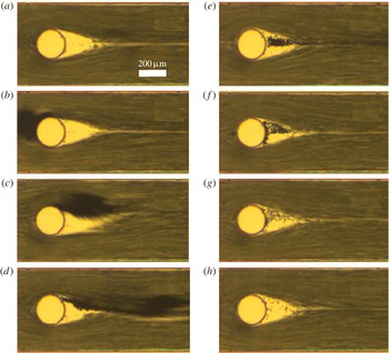
is the apparent viscosity, taking into consideration the effect of glycerol and particles. Figure 1 shows images during the flow of suspension of
 ${\it\phi}=0.084$
over a cylindrical obstacle at
 $Re=60,120$
and
 $300$
. Note the particle-depleted wake zone, where the colour is brighter. The particles appear dark in these images using backlighting. Because of the shallow depth of the channels, with
 $h=60\ {\rm\mu}\text{m}$
, the onset of unsteadiness and vortex shedding is at a larger
 $Re$
than the threshold for the flow of a pure fluid over a long cylinder, which has a value of
 $Re_{cr}\approx 55$
(Batchelor Reference Batchelor1967). We have not observed the recirculating wake to exhibit large-scale unsteady motion in our experiments; the flow at the microscale (on the scale of the particles) is unsteady for suspensions, but here we are commenting on the bulk unsteady behaviour as seen in a pure fluid beyond the noted threshold. At
 $Re=300$
, some particles are seen inside the wake which orbit close to the wake boundaries, while the core of the wake is clean. A weld line (which is the joining line of the divided streams) is seen downstream of the recirculating zone tail. In order to show that the depleted wake does not arise simply from sweeping away the particles which would be in this region at the start-up of flow, in figure 2 we show the sequence of events following an aggregated mass of particles flowing over the obstacle. In this experiment, after the wake region reaches a steady size, a clump of particles is released inside the channel, and this forces particles into the wake zone, where they are trapped. As time proceeds, the sequence of images clearly shows that the trapped particles circulate various numbers of times around the wake, depending upon their location, and eventually exit. This continues until the wake returns to the initial particle-depleted condition.
Sequence of images showing release of an aggregated mass of particles in the channel demonstrates that particles are trapped inside the wake after the passage of the aggregate. Particles exit the wake region and the final state of the wake is depleted of particles.

4. Simulation results
4.1. Dynamics of a single particle
We begin by presenting the simulated trajectory of an isolated particle released either in the free stream or inside the wake region. For this calculation, the particle is released after generating a steady-state closed-streamline zone at
 $Re=18$
, a condition which leads to a recirculating wake of approximately the same axial extent as the cylinder itself. Unlike the experimental observations, in which the presence of the walls and close placement of the cylinder to the walls of the channel delay unsteadiness of the wake and the recirculating wake zone remains steady for
 $Re$
up to 300 (Bearman & Zdravkovich Reference Bearman and Zdravkovich1978; Zovatto & Pedrizzetti Reference Zovatto and Pedrizzetti2011), the simulations in an unbounded domain may cause unsteadiness of the wake at
 $Re_{cr}\approx 55$
(Batchelor Reference Batchelor1967); the value of
 $Re$
in our simulations is kept below
 $Re_{cr}\approx 55$
to ensure formation of a steady wake.
Trajectory of a single spherical particle released in the wake zone at
 $Re=18$
for size ratios of (a)
 ${\it\delta}=0.09$
, (b)
 ${\it\delta}=0.2$
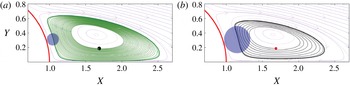
. The approach to the limit cycle is faster for a larger particle, and for a larger particle the limit cycle is smaller owing to the displacement at the cylinder surface. Movie 2 of the supplementary material shows the motion of the particle towards the limit cycle. The axes are scaled to the cylindrical obstacle radius.

A single particle released in the free stream passes the cylindrical post and remains separated from the wake region. No entry to the wake was observed at any position of release for the particle-to-cylinder size ratios studied (
 ${\it\delta}=0.09,0.16$
and 0.2). A sample trajectory for a single particle released in the free stream is provided in supplementary movie 1 available at http://dx.doi.org/10.1017/jfm.2014.613. Considering now single particles released inside the wake, figure 3(a,b) show particle trajectories for size ratios of
 ${\it\delta}=0.09$
and
 $0.2$
. The steady-state recirculating wake in the absence of particles is made up of closed streamlines, with fluid elements orbiting with a cyclic return to their initial position. However, the particles released inside the wake are displaced outwards at each orbital cycle. The outward motion of the particles continues until approaching a limiting trajectory, which is in dynamical systems termed a limit cycle. During each circuit of the limit cycle, the particle interacts with the cylindrical obstacle. The particle–post interaction prevents the particle from further outward motion and adjusts the location of the particle on the trajectory. Because of this close interaction with the post, the limiting trajectory of the larger particle stands farther from the obstacle surface and closer to the wake core. The outward motion is more rapid for larger particles, i.e. at
 ${\it\delta}=0.2$
the displacement is more rapid than at
 ${\it\delta}=0.09$
; it should be noted that the bulk fluid motion, and hence the time scale of the flow, is the same for the three particle sizes. A sample trajectory for the
 ${\it\delta}=0.09$
particle released inside the wake zone is provided in supplementary movie 2.
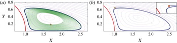
It is important in describing the limiting trajectory as a limit cycle to observe that particles released outside the limit cycle can also be attracted by the limit cycle, which thus has a basin of attraction in each direction normal to itself. We demonstrate this in figure 4. Figure 4(a) shows the limit cycle for
 ${\it\delta}=0.09$
. A particle with starting point close to the wake centre migrates outwards until reaching the limit cycle. Figure 4(b) shows that a trajectory which starts its motion from outside the limit cycle is also attracted by the limit cycle, with the inset providing a magnified view of the starting point of the trajectory. Our observation is that trajectories attracted by the limit cycle from the outside are located with the particle centre inside the recirculating wake region of the particle-free flow, although we have not rigorously tested the limits of the basin of attraction. The formal limit-cycle behaviour appears to not be limited to a single particle. Supplementary movie 3 shows a pair of particles placed on the limit cycle reaching a stable motion with an equilibrium separation; this is found for a number of configurations, but we have not rigorously examined all initial positions of pairs in the wake to establish the generality of this result. In addition to neutrally buoyant particles, we have observed a stable limit-cycle trajectory for particles with slightly higher density than the fluid, i.e.
 ${\it\rho}_{p}/{\it\rho}_{f}=1.2$
, where
 ${\it\rho}_{p}$
and
 ${\it\rho}_{r}$
are the particle and fluid densities, respectively.
The limit cycle, showing attraction of trajectories in the wake region: (a) Trajectories that stream from inside the limit cycle are attracted to the limit cycle. The initial point of the sample trajectory is indicated in the figure. (b) A sample trajectory that begins from outside of the limit cycle, but still inside the recirculating wake of the pure fluid flow, moves inwards to the limit cycle; the inset provides an enlarged view of the starting point of the trajectory. The axes are scaled to the cylindrical obstacle radius.

4.2. Particle dynamics in flow of the suspension
The stable motion of one and possibly two particles on the limit cycle, described above, is perturbed by the presence of sufficient numbers of other particles which generate velocity fluctuations. The deviation in the motion of the particles from the limit cycle can be in any direction, and disturbances outward tend to cause transfer of particles from the recirculation into the free stream. We demonstrate this phenomenon in figure 5, showing a sequence of images of the positions of five particles released into the wake at
 $Re=18$
. The particles all begin and remain on the
 $xy$
plane, i.e. with
 $z=0$
. The dynamics can also be viewed in supplementary movie 4. After release, particles follow near-orbital paths with an outward motion, consistent with the single-body dynamics described above. Interactions of the particles with one another result in fluctuations, which eventually cause one of the particles to exit the closed-streamline zone entirely. The exit point is at the downstream end of the wake, which is a hyperbolic point. This calculation is done with no particles in the free stream, and thus illustrates that particle interactions strictly within the wake can move particles off the limit-cycle trajectory, providing one mechanism for depletion of the wake by entry into the free stream.
Three sequential images showing the positions and trajectory tracks for motion of five particles released into one lobe of the recirculating wake behind a cylinder at
 $Re=18$
. Particles move outwards and fluctuations due to interactions push one particle to the other lobe of the wake and one particle out of the wake into the free stream.

Next we study the flow of suspensions of
 ${\it\phi}=0.04,0.06$
and
 $0.08$
over the cylindrical obstacle at
 $Re=24$
. The size of the wake region for pure fluid flow at
 $Re=24$
is almost equal to the wake size at
 $Re=18$
, which has been previously used to simulate the dynamics of particles in the wake. At
 $Re=24$
, the inertia at the particle length scale is characterized by
 $Re_{p}={\it\delta}^{2}Re$
, with
 $Re_{p}=0.2$
and
 $0.6$
for
 ${\it\delta}=0.09$
and
 $0.16$
, respectively. This definition of
 $Re_{p}$
depending on the square of the particle size is consistent with the definition typically used in shear flow studies (e.g. Haddadi & Morris Reference Haddadi and Morris2014), as it is the relative motion on the particle scale that is relevant in such conditions, although a definition of
 $Re_{p}$
scaling linearly with the particle size might also be used here. From these simulations, we observe the effect of velocity fluctuations due to interactions with particles in the free stream and in the wake zone. Figure 6 presents sample trajectories in flow of a
 ${\it\phi}=0.06$
suspension over the cylindrical obstacle, where we observe a particle exchange between the wake and the free stream: both entry to and exit from the wake are illustrated. Mass exchange between the wake and the free stream in flow of the suspension over the obstacle is in contrast with the behaviour of the fluid mechanical wake, where there is no mass exchange between regions; the transport of particles across the limit-cycle trajectory arises from multiple particles interacting, as it is not seen for the single-particle situation.
Three observed trajectories illustrating particle transfer into and out of the recirculating region for flow of a suspension of
 ${\it\phi}=0.06$
over the circular cylinder.

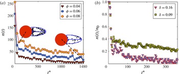
(a) The average number of particles in the wake plotted as a function of dimensionless time
 $t^{\ast }=t{\bar{U}}/D$
at
 $Re=24$
, for three different volume fractions and
 ${\it\delta}=0.09$
. (b) The ratio of particles in the wake zone at each sampling time,
 $n(t)$
, to the initial number of particles in the wake,
 $n_{0}$
, for
 ${\it\phi}=0.06$
and two size ratios,
 ${\it\delta}=0.09$
and
 $0.16$
.

Figure 7 shows the number of particles inside the wake region for
 $Re=24$
; this is the total across the entire wake volume in the
 $z$
(cylinder axis) direction, which extends a distance of twice the cylinder diameter before periodic repetition. Because the wake boundary is an imprecise surface in suspension flow, the calculations are based on the number of particles with centres inside the steady-state wake boundary for the pure fluid at the same
 $Re$
. Figure 7(a) shows that after the initial stage of the flow, when the number of particles in the wake region drops suddenly due to sweeping away in the flow start-up, the number of particles in the wake decreases approximately linearly in time, plotted as
 $t^{\ast }=t{\bar{U}}/D$
, with
 $t$
being the dimensional time. The particle distributions in the wake zone at two stages are also demonstrated in figure 7(a). As time proceeds, particles marginate towards the recirculating wake boundary, and the core region of the wake becomes depleted. Figure 7(b) shows the average number of particles for size ratios of
 ${\it\delta}=0.09$
and
 $0.16$
. It was noted previously that the motion towards the limit-cycle trajectory is faster for larger particles due to their larger particle-scale inertia. Here, the faster approach of the larger particles (
 ${\it\delta}=0.16$
) towards the wake boundary exhibits its effect as a faster depletion of the wake region: once the particles are located near the wake boundary, disturbances by other particles in either the recirculating wake or in the free stream flow can lead to exit from the wake.
5. Conclusion
In this study of the flow of a suspension of monodisperse and neutrally buoyant particles over a cylindrical obstacle, we have used numerical simulations to provide insight into a distinctively multiphase phenomenon in a recirculating wake flow. The experimental observations in a microfluidic device demonstrate the formation of a particle-depleted region in the wake behind a cylindrical obstacle. Numerical simulation by the LBM of the unbounded flow over a cylinder, rather than in the more confined microfluidic flow, have been utilized to study the dynamics of particles and elucidate the basis for the experimental observations.
Numerical investigations at the single-particle level showed that a single particle in the free stream does not enter the wake. A single particle released inside the wake region moves towards the boundary of the wake, while orbiting inside the wake region, until reaching a limit-cycle trajectory; it has been shown that this is formally a limit cycle in the sense that it has a basin of attraction of the entire region interior to the limit-cycle trajectory, and an adjacent region lying within the pure fluid wake zone but outside the limit cycle itself. The migration towards the limit cycle is faster for a larger particle, which carries more particle-scale inertia. However, for larger numbers of particles introduced into the wake, stable motion on the limit cycle is perturbed by fluctuations caused by multiple particle interactions, and particles can move from one lobe of the wake to the other, or completely exit the wake by escaping into the free stream. Simulations of the flow of monodisperse suspensions at solid fractions of
 ${\it\phi}=0.04,0.06$
and
 $0.08$
over the circular cylindrical obstacle show that a particle exchange across the boundary of the recirculating region occurs. The number of particles in the wake region decreases with time and the wake moves towards the depleted state. Progress towards the depleted state is faster for a suspension of larger particles.
A primary conclusion to be drawn from this work is that understanding phenomena associated with multiphase flow in such basic flow structures as recirculating wakes requires additional considerations relative to single-phase flows, and these phenomena are not likely to be captured by existing effective-medium descriptions of the suspension. Based on the results of numerical simulations, the mechanism of particle-depleted wake formation is found to be a combination of the cross-streamline motion of particles, caused by inertia at the particle scale (studied here for
 $Re_{p}={\it\delta}^{2}Re=0.2$
to 0.6, with
 ${\it\delta}=d/D$
the particle diameter relative to the post diameter), and the interaction of particles to perturb the stable motion of particles on the limit-cycle trajectory. Unlike a pure fluid flow, where the recirculating wake is an isolated region bounded by a material surface, transport across the mean wake boundary may occur due to these microscale fluctuations. The wake structure has, as one would expect, very persistent effects. The first is that the wake structure interacts with the inertia at the particle scale to determine the limit-cycle trajectory of one or two particles, a trajectory which depends upon the size of the particles relative to the cylindrical obstacle (
 ${\it\delta}$
in our notation); importantly, the tendency towards this limit cycle is seen also for many particles. Second, once the particles migrate into proximity to the limit-cycle trajectory – or what would be such for one or two particles – interactions with others in the wake or in the free stream are sufficient to cause net particle transport out of the wake.
Acknowledgements
The work of H.H. and J.F.M. was funded by NSF grant CBET 0847271. K.C. was supported by NSF PREM (DMR 0934206). This research was also supported, in part, by a grant of computer time from the City University of New York High Performance Computing Center under NSF Grants CNS-0855217, CNS-0958379, and ACI-1126113. We are grateful to Professor A. J. C. Ladd of the University of Florida for providing the initial LB code.
Supplementary movies
Supplementary movies are available at http://dx.doi.org/10.1017/jfm.2014.613.