I. INTRODUCTION
Severe plastic deformation (SPD) in metallic systems is accompanied not only by grain refinement, which endows it with strength,Reference Tellkamp, Melmed and Lavernia1–Reference Youngdahl, Weertman, Hugo and Kung4 but also by generation and organization of high density of crystal defects. The energies stored in various configurations of these defects provide the driving force for most observed recovery and recrystallization phenomena.Reference Humphreys and Hatherly5–Reference Bever, Holt and Titchener9 Dislocations that contribute to most of this stored energy in severely deformed materials are mostly integrated into grain boundaries, cell boundaries, or complex entanglements that are prone to annihilation in response to heating, resulting in microstructural transformation.
Thus far, most of the work on SPD has used low strain rates (∼0.1/s to 10/s), except for a few recent works wherein strain rates of the order of 103 were usedReference Li, Zhang, Tao and Lu10–Reference Shekhar, Cai, Wang and Shankar12 and resulted in intriguing property combinations. One of these studies (Ref. 10) used dynamic plastic deformation instead of SPD where they obtained high levels of plastic deformation through repeated compressive deformation at high strain rates. While in the works mentioned in Refs. 11 and 12, we used high shear strain rates for SPD where strains of the order 3–5 and strain rates of the order of ∼103 were obtained in one pass of deformation. The interplay of large shear strains and high strain rates and the supplementary effect of temperature rise near the deformation zone that accompanies the high strain rates, as modeled in our earlier work, gives rise to novel microstructures and subsequently, enhanced material properties.Reference Cai, Shekhar, Wang and Shankar11, Reference Shekhar, Cai, Wang and Shankar12 We have shown that high strain rate SPD can lead to dense dispersion of nanotwins in low stacking fault energy (SFE) material, like brass.Reference Cai, Shekhar, Wang and Shankar11 In the case of copper, we found that high strain rate SPD and the accompanying flash heating lead to bimodal grain size distribution with modes at 500 and 2000 nm.Reference Shekhar, Cai, Wang and Shankar12 Such multimodality was shown to lead to a significant increase in ductility of these samples. The flash heating in the deformation zone can, in addition, lead to temperature-induced dynamic recovery, which is a microstructural transformation process that takes place by annihilation of defects, and hence can be expected to alter the stored energy and thus can be related to the changes in microstructure.
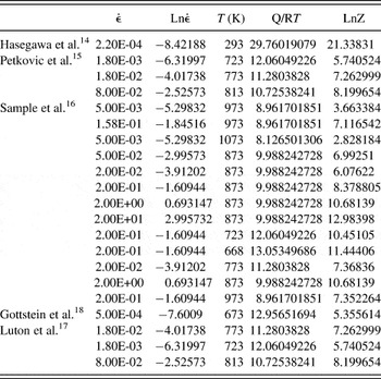
Recovery and recrystallization phenomena have been studied extensively.Reference Gottstein and Kocks13–Reference Gottstein, Zabardjadi and Mecking18 However, most of these studies, including the ones for dynamic recovery, have focused on low strain rate (∼0.01 to 1.0) and high temperatures (>400 °C). In this study, we look at an altogether different regime of strain, strain rate, and temperature, which can induce interplays of recovery and recrystallization phenomena leading to novel fine-grained materials. The difference in the present study from the earlier studies can be highlighted in the following points: this study uses (i) high strain values—of the order of three and higher as compared to a max strain value of 0.5 in the aforementioned references; (ii) high strain rate—in the range of 200 to 4500/s as compared to the highest strain rate of 20/s in the earlier studies; and (iii) we do not heat the samples, but there is an in situ temperature rise that was calculated to be always less than 300 °C. These parametric differences are also evident from the Z (Zener–Hollomon parameter) values calculated for various studies (see Table I). The highest Ln(Z) value for most of these earlier studies is less than 13, except for Hasegawa et al.,Reference Hasegawa and Kocks14 while the lowest Ln(Z) value calculated for our experiments is above 23, as mentioned in Tables I and II. Hasegawa et al.Reference Hasegawa and Kocks14 deformed aluminum samples at room temperature and then studied the recovery ex situ by annealing these samples at 180 °C.
Zener–Hollomon parameter for earlier studies on recovery and recrystallization of copper.

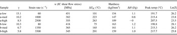
SPD shear strain (γ), strain rate, resulting hardness values, stored energy from DSC (ΔH), temperature value for peak energy release during DSC, dynamic temperature rise in the deformation zone (ΔT JC) and shear flow stress in the deformation zone (κ) calculated using JC model by recursive iteration for various samples that were examined. (“a” samples were obtained using a rake angle of 0° while “b” samples were obtained using a rake angle of 20°.)

The scale of the deformed grain structures examined in this study is also very different from earlier studies. SPD results in grains of the order of a few hundred nanometers as compared to polycryststalline and single crystalline samples used in earlier studies. It is important to note here that the temperature-induced microstructural transformation that we observe here can neither be classified as static recovery—which is the change in microstructure with time at a particular temperature after some prestrain, nor dynamic recovery—which is the change in microstructure brought on by an increase in strain alone, during the deformation process at a given temperature. The “dynamic recovery” here is instigated by the rise in temperature caused by high strain and strain rate that the material is subjected to, and hence can be termed as temperature-induced dynamic recovery.
In this work, we investigate the effect of in situ heating resulting from large strain rates on severely deformed microstructures and its effect on the stored energy. We also related the microstructures with the variation in stored energy and this in turn enabled us to demarcate different stages of recovery and recrystallization. To this end, we undertook an exploration of thermomechanical deformation of copper across a wide range of strains, strain rates that involve varying levels of exposure to in situ heating in the deformation zone to realize different degrees of recovery and recrystallization.
II. EXPERIMENTAL METHODS
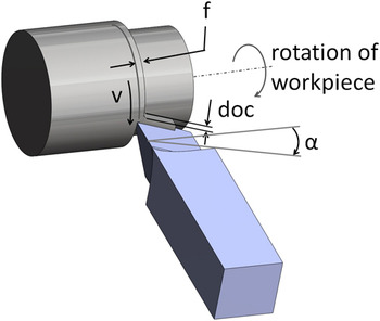
Chip formation by machining emerged as our choice of method for severe plastic deformation because of its versatility to impart a large range of strain and strain rate in a single deformation pass in a range of material systems.Reference Swaminathan, Ravi Shankar, Lee, Hwang, Rao, King, Chandrasekar, Compton and Trumble19–Reference Swaminathan, Ravi Shankar, Rao, King, Chandrasekar, Compton and Trumble25 This allowed us to scan across wide ranges of strain rate (∼101–103/s) and strains while still creating fully dense bulk samples that were still large enough for reliable thermal and mechanical analysis. The magnitude of strains in the chip during machining can be controlled by an appropriate choice of the rake angle of the cutting tool (α), and the strain rates are determined by the velocity of tool advance or the machining speed (V) (see Fig. 1).Reference Lee, Hwang, Ravi Shankar, Chandrasekar and Compton22 The necessary control over strain and strain rates were achieved through appropriate choices of these parameters. We used a machining configuration as shown in Fig. 1, with a depth of cut value, which determines the width of the samples, as 3 mm and feed rate (f), which determines the thickness of the undeformed chip, as 0.17 mm. This configuration where the width is much larger than the undeformed chip thickness offers a plane strain simple shear configuration for imposing SPD across a range of strains, strain rates, and temperature values.Reference Swaminathan, Ravi Shankar, Lee, Hwang, Rao, King, Chandrasekar, Compton and Trumble19, Reference Lee, Hwang, Ravi Shankar, Chandrasekar and Compton22, Reference Childs, Maekawa, Obikawa and Yamane26
Machining configuration and various parameters associated with machining. The “chip” coming out of machining makes the sample.

A. Material system
We used commercially pure oxygen-free high conductivity copper as our material system and annealed it at 700 °C for 2 h and subsequently machined it to create severely deformed chip samples using different rake angles (0°, 20°) resulting in different shear strains, at three different machining speeds (low = 50 mm/s, med = 589 mm/s, and high = 1274 mm/s). The shear strain values were calculated using the geometry of the final chip as described in Ref. 26. The strain rates can be calculated directly from shear strain values and the machining speed as explained in Ref. 27. In all, copper was machined at six different conditions, from here on referred to as a-low, a-med, a-high, b-low, b-med, and b-high. The “a” and “b” refer to two different rake angles used: 0° and 20°, respectively. The “low,” “med,” and “high” refer to the three different strain rates used to obtain these samples. The shear strain and strain rate values for all these samples are listed in Table II.
B. Mechanical testing
Hardness tests were conducted on all these samples using a Shimadzu microhardness tester (HMV-2, Kyoto, Japan). The samples were placed into epoxy mount and polished until 0.05-μ alumina. A force of 490.3 mN was used for measuring the hardness values. A minimum of 10 measurements were taken to find an average value and the standard deviation. The standard deviation was found to be less than 6% for all samples.
C. Differential scanning calorimetry (DSC) analysis
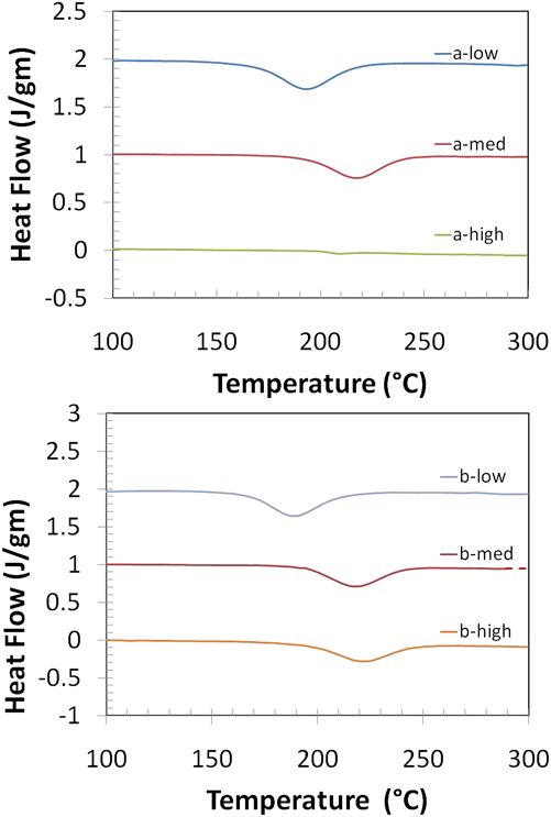
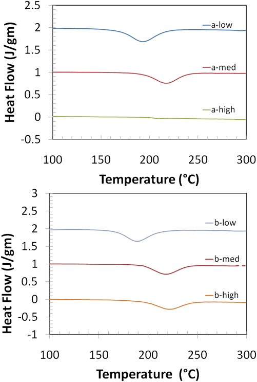
For an array of these specimens, the stored energy of the samples was measured by conducting DSC using a Perkin Elmer Diamond DSC system (Waltham, MA). The DSC plots for various samples are shown in Fig. 2. Samples in the shape of discs were prepared with a diameter of 3–5 mm and a thickness of 1–2 mm. The samples were polished with SiC paper and then stress relieved using an acidic solution composed of a suitable mixture of nitric acid, ascetic acid, and phosphoric acid to get rid of any surface deformation, which may influence the total energy released. The weight of most of the samples was between 20 and 40 g, which were found to be optimum, after conducting several tests on samples of varying weights, for measuring stored energy, which is of the order of 1 J/g. Standard aluminum pans were used to encase the sample and an empty aluminum pan was used as reference. To determine the baseline, each sample was reheated at the same condition and the resulting heat flow was subtracted from the original heat flow. This provided individual baseline for each sample, thus ensuring high accuracy of the results. A detailed review of use of DSC for calculating stored energy for SPD materials can be found in Ref. 28.
DSC plots for various samples (a) a-low, a-med, and a-high samples and (b) b-low, b-med, and b-high samples. (The various plots were shifted by 1 J/g unit on the y axis to display various samples on one plot.)
D. Electron microscopy
Small discs of 3 mm diameter were cut from the relevant samples to characterize using transmission electron microscopy (TEM) in a JEOL 200-CX microscope (JEOL Ltd., Tokyo, Japan). The samples were prepared using a double-jet electrolytic polishing machine in a Struers Tenupol-5 system (Ballerup, Denmark).
Samples were also prepared for orientation imaging microscopy (OIM) using electron backscattered diffraction (EBSD). The samples were prepared by polishing down to 0.1 μ by hand and then placed into a vibratory polisher with 0.05-μ alumina solution for 1–2 h for final polishing. OIM was carried out using a Phillips XL-30 system (Eindhoven, The Netherlands) equipped with the EDAX-Ametek EBSD detector (Amsterdam, The Netherlands) featuring a Hikari Camera and TSL OIM software (EDAX, Mahwah, NJ) for data acquisition and analysis. All these images were taken using a step size of 0.1 μ and the scan size was 15 μ × 15 μ for each sample except for the a-high sample for which the scan size was 25 μ × 25 μ. We also used the TSL analysis software to measure the length of regular (15°–180°) grain boundaries and subgrain boundaries (2°–15°). We then calculated “f” to measure the length of subgrain boundaries as a fraction of the total length of all boundaries.
E. Infrared (IR) thermography
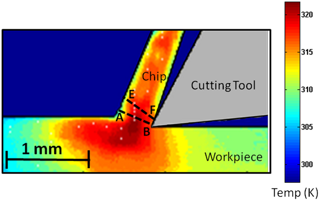
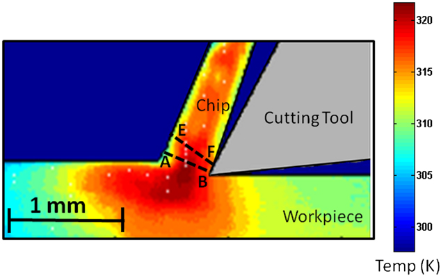
The IR thermography was performed to measure the temperature rise and compare the values with that predicted from our model. We used a FLIR A325 camera (Wilsonville, OR), which can measure temperatures up to 400 °C (∼675 K) for this purpose. The IR camera was focused on the middle of the deformation zone ahead of the tool tip in the plane-strain machining configuration and the resulting images were utilized to calculate the temperature field. A typical thermograph obtained while machining at 50 mm/s using a rake angle of 40° is shown in Fig. 3.
IR thermograph for machining of copper on a linear setup using a rake angle of 40° at a speed of 50 mm/s. Most of the temperature rise is concentrated in the region ahead of the tool tip, which underscores the fact that the primary deformation zone is the main contributor to temperature rise in the material and the chip.
III. RESULTS
The shear strain, strain rates, and the hardness values of all the samples considered are listed in Table II. It is also useful to note here that, in general, shear strains decrease with increasing rake angle and tend to decrease with increasing strain rate for a given rake angle. Because the shear strain values are high, it would be expected that the hardness values would be saturated and all the samples would show similar hardness. We found an interesting anomaly in a-high and a-med, which showed much lower hardness values than the rest of the samples. We will demonstrate in the ensuing that this can be traced to in situ flash heating during machining caused by temperature rise at high strain rates. Depending on the amount of temperature rise, recovery can take place up to different stages and if the temperature rise is too high, material may dynamically undergo subgrain growth or recrystallization and result in substantial softening.
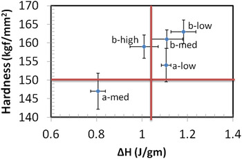
To examine the effect of this in situ temperature rise on the stored energy, we carried out DSC on our samples over a temperature range of 50–300 °C. Energy values for all the copper samples are also listed in Table II along with the peak temperature at which this energy was released. To better visualize the data, we plotted the energy release observed in the various samples as a function of hardness for the various samples in Fig. 4. Here, we found that stored energy is highest for the b-low sample, which also showed the highest hardness value. The samples a-low, b-med, and b-high show comparable stored energies and comparably high values of hardness, while a-med shows a somewhat lower hardness value and a smaller stored energy. We also note from Table II that stored energy value for the a-high sample, which showed low hardness, is almost negligible.
Hardness plotted against the stored energy for various copper samples. The top left quadrant designates materials with high strength and low stored energy. Top right quadrant shows materials with high strength, but high stored energy, e.g., nanostructured materials. Bottom left quadrant shows material with low strength and low stored energy, e.g., the usual polycrystalline materials. Bottom right quadrant is for materials with low strength and high stored energy.

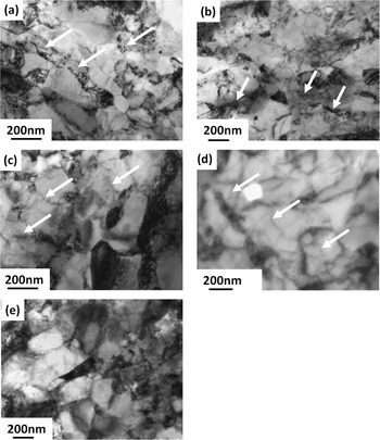
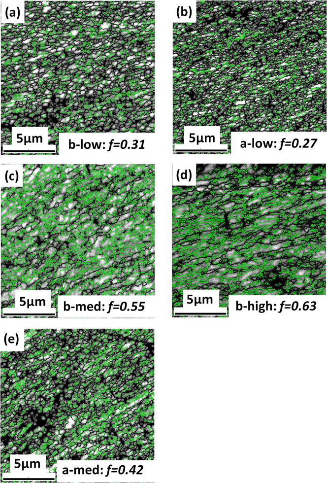
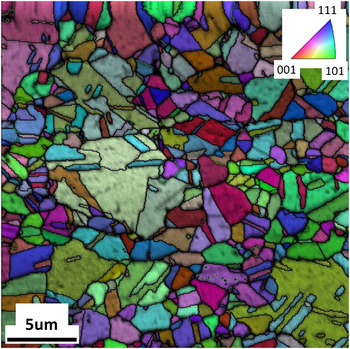
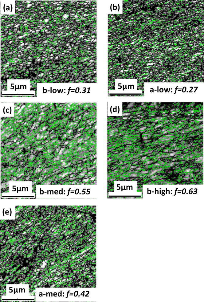
TEM images for all the samples are shown in Fig. 5. We observed a very high level of refinements for a-low and b-low samples that are consistent with what might be expected from imposition of high deformation shear strains at the low strain rates. On the contrary, we observed moderate levels of refinement in a-med, b-med, and b-high samples where we observed substantial dislocation networks and tangles. To acquire a more statistically significant sampling of the microstructure across a wider length-scale, we performed an EBSD analysis of the samples (Fig. 6). Here, we observed that the scale of the microstructure is generally in agreement with what was observed in our TEM study. Additionally, we confirm that a-low and b-low samples are indeed characterized by a preponderance of high-angle grain boundaries intermixed with a small fraction (f) of low-angle boundaries (f ∼0.3). On the other hand, the samples created at the higher strain rates (b-med, b-high, and a-med) are characterized by a high fraction of low-angle boundaries. Yet, we note the rather fine-scale of these low-angle boundaries in these samples created at the high strain rates. This observation affords some rationalization of the observed stored energies in the various samples that appears to decline with increasing deformation rates with b-low > b-med > b-high and a-low > a-med > a-high. Figure 7 illustrates the rather coarse grain structure in the a-high samples that indicate substantial recovery and even recrystallization of the sample.
TEM micrographs for (a) b-low: arrows point to random distribution of dislocations indicating stage-I of recovery; (b) a-low: arrows indicate to the presence of dislocations and cell walls that start to form in this sample are also visible; (c) b-med: arrows point to cell walls indicating stage-II of recovery; (d) b-high: arrows point to subgrain walls indicating later stages of stage-II of recovery; (e) a-med: illustrating much larger grains indicating grain growth occurring in stage-III.

Image quality maps obtained by EBSD to show the variation in fraction of low-angle boundaries along various stages of recovery: (a) b-low sample in stage-I; (b) a-low sample, which has just entered stage-II; (c) b-med sample in stage-II; (d) b-high sample near the end of stage-II; (e) a-med sample in stage-III. The black lines indicate the regular grain boundary (>15°), while the light lines indicate the low-angle boundaries (2°–15°). The f is fraction of low-angle boundaries (step size = 0.1 μ). There is a gradual increase in the low-angle boundary fraction f from a-low and b-low sample through b-med and finally to b-high sample. However, there is a sudden drop in the f-value for the a-med sample.
OIM of a-high sample showing coarse grain structure indicating recrystallization. Inset shows the color scheme for the orientation of the grains. This micrograph clearly shows the recrystallized microstructure that is obtained for the a-high sample. (Black lines indicate the high-angle grain boundaries and light lines show the low-angle boundaries.)

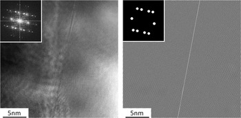
Additionally, we observed a dispersion of twins in the b-high sample that appeared to coexist among the network of the ultrafine high- and low-angle boundaries. A typical high-resolution TEM (HRTEM) image showing twin boundary in this sample is shown in Fig. 8(a). The inset shows the fast Fourier transformation (FFT) pattern obtained for this image and masks were used to obtain inverse FFT to reveal the twin boundary, as shown in Fig. 8(b). Note the rather pristine structure of these twins in this image.
HRTEM image of sample b-high showing twin boundary. (a) Bright-field image along with the FFT pattern in the inset; (b) inverse FFT image obtained from the FFT diffraction pattern, using the mask shown in the inset.

IV. DISCUSSION
The behavior of plastic deformation systems for a given material and prior microstructure is expected to be controlled by the interactive effects of shear strain, strain rate, and the temperature in the primary deformation zone ahead of the tool tip. In this study, we examined SPD at a range of strain rates in samples that were nominally deformed at room temperatures, even though the temperature in the deformation zone is expected to be elevated. Here, the temperature in the deformation zone is not an independent variable, but a function of the shear strain and the strain rate. And, we can intuitively foresee that the higher the shear strain and the strain rate, the higher the temperature in the deformation zone and vice versa. However, the temperature in the deformation zone also modifies the constitutive behavior, thus interacting with the accommodation of the shear strain and the strain rates, and manifesting the myriad of resulting deformed microstructures and associated thermomechanical property combinations.
Capturing these interactions is crucial for rationalizing our experimental results. To this end, we used a machining model due to Weiner that is based on the moving heat source principles.Reference Childs, Maekawa, Obikawa and Yamane26 The deformation zone temperature in machining depends primarily on (i) ratio of primary flow stress to heat capacity, (ii) deformation of shear strain, and (iii) thermal number “α,” defined as (V.f.tan φ)/4*κ, where “f” is the feed rate (or the undeformed chip thickness) in machining, φ is the primary shear plane angle, κ is the thermal diffusivity of the material, and V is the speed of machining that is also directly proportional to the strain rate in machining. It has been shown that temperature rise in the deformation zone ΔT is given by Ref. 26: ΔT = (1 − β)*kγ/(ρc), where β is the partition parameter that determines fraction of heat taken away by the bulk work piece, k is the shear flow stress, γ is the deformation shear strain imposed during machining, and (ρc) is the heat capacity of the work material. Heat capacity (ρc) of copper was taken as 3.45 MJ/m3.Reference Johnson and Cook29 The β can be estimated using the equation given by WeinerReference Weiner30:

where α is the thermal number. Shear flow stress, k, can be calculated from  , where σ is the tensile strength. However, this flow strength is itself a function of shear strain and strain rate and also the temperature in the deformation zone. This effect is reasonably captured by material models such as the Johnson and Cook (JC) equationReference Johnson and Cook29:

where  is the dimensionless plastic strain rate,
 and T* are defined as T* = T − 293/T mp − 293. A, B, n, C, and m are five material constants, which were obtained empirically and their values are A = 90 MPa, B = 292 MPa, n = 0.31, C = 0.025, and m = 1.09 for copper.Reference Johnson and Cook29 The JC model provides good strain rate dependence of stress at moderately high temperatures and high strain rates, which is where our experimental results are expected to lie. These two models (Weiner model for temperature calculationReference Weiner30 and JC modelReference Johnson and Cook29 for stress calculation) setup a thermomechanically coupled problem where we need to know the temperature rise to calculate the shear strength values, which in turn is required to calculate the temperature rise. The equations for ΔT(σ, ε,
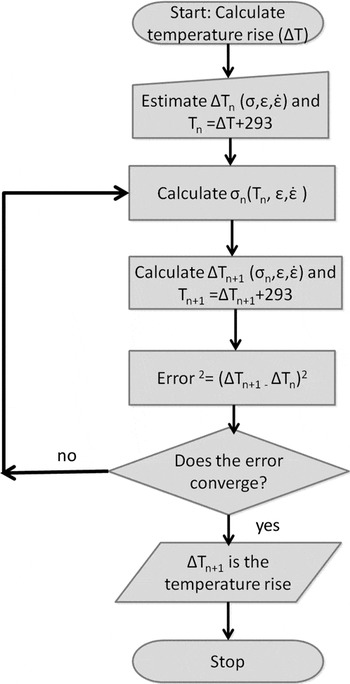
 ) and σ(ΔT, ε,
 ) can be solved using recursive iteration, the flowchart is shown in Fig. 9. The first run of the iteration begins with an initial guess of the temperature rise. We use this temperature rise to calculate the homologous temperature and then use the JC model to calculate the shear stress and subsequently the temperature rise using the moving heat source model. This temperature rise is then used to compute the error between the guessed temperature rise and the calculated temperature rise. Subsequently, regression is used to improve the guess until the error between the temperature rise input into the JC model and that calculated from the moving heat source model converge to a sufficiently small value. Using this approach, we calculated the temperature rise (ΔT JC) and the shear flow stress in the deformation zone (k) for the various SPD conditions in Table II. Note that much of this temperature rise primarily occurs in the deformation zone and during the transit through the deformation zone; the material is subjected to this flash heating after which it cools very rapidly. The ΔT JC value was also calculated for the machining condition for which IR thermography was done (rake = 40°; speed = 50 mm/s) and was found to be 40.5 °C, hence the expected temperature in the deformation zone would be T = 293 + ΔT JC = 333.5 K. In the thermograph shown in Fig. 3, we see that the temperature in the deformation zone is 324 K, which is very close to the calculated value. This result reinforces our expectation that this methodology can be used to accurately model the temperature rise and shear strength for a given machining condition.
Flowchart to show the calculation of temperature rise (ΔT) and shear stress (σ) by the recursive iteration process.

We note that we are considering the strain rate and temperature rise due to the primary deformation zone alone and the secondary effect due to frictional heating at the tool-chip interface have been ignored. It has been demonstrated that the effect of frictional heating scales with the cutting speed (V) and has an effect on the deformation zone temperature at speeds much higher than those considered here.Reference Childs, Maekawa, Obikawa and Yamane26 It is important to point out that for the temperature field in Fig. 3, the camera is focused on the deformation zone, ahead of the tool tip and the comparison between the model and the measurement is valid exclusively for this zone. Further away from the deformation zone, outside the focal region of the camera, it may be misleading to interpret the results to elucidate the characteristics of the thermomechanical deformation field. Still, it is noteworthy that even in the vicinity of the focused zone ahead of the tool we do not observe any significant “hot spots” due to secondary frictional heating at the tool-chip that approaches the temperature rise due to the SPD. This is in line with the expectation that for the deformation speeds considered here, the contribution from frictional heating is small.
This model now enables us to calculate the deformation zone temperature for a range of shear strain and strain rates in machining to then identify the regions to which the various samples belong (Fig. 10). The horizontal axis is the strain rate plotted on a logarithmic scale to cover a large range of strain rates and the vertical axis represents the shear strain values. The six sample conditions that were used in our experiments are also shown on the plot. Colored bands depict expected temperature in the deformation zone for the given shear strain and strain-rate conditions, and these values increase monotonically as we go toward the top right corner of the map where both shear strain and strain rates are high. The various stages in this figure are demarcated in the context of the DSC results as delineated subsequently.
Color-coded map showing the various parameters that influence the final microstructure: shear strain, strain rate, and the temperature in the deformation zone (293 + ΔT), where ΔT was calculated using recursive iteration. Various samples used in the study are shown on the plot. (The temperature values are in Kelvin.)

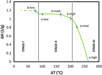
To understand temperature rise of the various samples in context of the stored energy, we plotted stored energy as a function of temperature rise (Fig. 11). It is immediately apparent that the variation of the stored energy with the deformation zone flash heating temperature collapses to a single curve, which has been drawn schematically and superimposed on this figure. Furthermore, to find the extent of the different stages of recovery on this plot, we looked at the stored energy, hardness values, and temperature rise of these samples as listed in Table I. We see that sample a-high, which showed a low hardness value and a high temperature rise, has almost negligible stored energy. The negligible energy value implies that this sample underwent a complete recovery process and experienced full microstructural transformation. This was confirmed by an OIM micrograph obtained for this sample (Fig. 7), which showed coarse grains, and is in contrast to the ultrafine grains expected at the shear strain values to which this sample was subjected. The temperature rise for this sample was calculated from our iterative method indicated in Table I as ∼263 °C, the highest among all the samples. We therefore conclude that this sample was subjected to a high dynamic temperature rise in the deformation zone that entailed its nearly complete recrystallization and hence the observed softening, despite the otherwise high level of SPD. This corresponds to stage-III in Figs. 10 and 11.
Variation of stored energy with respect to temperature rise ΔT is plotted along with a schematic depiction of three stages of recovery and eventual subgrain growth regime.

We note from Table II and Fig. 4 that hardness values of b-low are high and so is the stored energy. Moreover, the calculated temperature rise in the deformation zone from Table I, for this sample is modest (∼75 °C). Under the slow strain-rate conditions, it is thus unlikely that these samples have undergone any significant recovery. Hence, it can be interpreted that this sample is in the first stage of the recovery process, which is similar to the first stage of static recovery where nominal annihilation of dislocations occur due to thermal agitation. This level of recovery is demarcated as stage-I in Figs. 10 and 11. This would also imply that the deformation of this sample is similar to other slow strain rate SPD of Cu, such as Equal Channel Angular Pressing (ECAP), and we find evidence of this in the stored energy observed for SPD of Cu obtained by other slow strain-rate processes, which were comparable to that in this study.Reference Li, Zhang, Tao and Lu10, Reference Jiang, Zhu, Butt, Alexandrov and Lowe31–Reference Li, Zhang, Tao and Lu33 The a-low sample shows a relatively higher temperature rise (∼101 °C) than the b-low sample and also has lower energy compared to it. It can be extrapolated that this sample condition is in stage-II of the recovery process. Furthermore, we see from Table II that the b-med sample shows high strength and a moderate temperature rise (∼165 °C), however, the stored energy in this sample (1.1 J/g) is still comparable to the a-low sample (1.1 J/g), implying that the in situ thermal agitation in the b-med sample is insufficient for causing rampant recovery or coarsening. Therefore, we can surmise that this sample is likely in stage-II of recovery. The b-high and a-med samples show a relatively high temperature rise (∼201 and ∼223 °C, respectively) in Table I, however, the hardness values of a-med is significantly lower than the hardness value of b-high, even though the shear strain values of a-med are about twice that of b-high. The energy stored in sample a-med (0.8 J/g) is also significantly lower than the energy stored in sample b-high (1.0 J/g). It can be extrapolated from these values that the dynamic recovery of the b-high sample is somewhere in the vicinity or end of stage-II, whereas recovery for a-med went past stage-II and into the grain growth regime leading to its softening. On the basis of these arguments, we demarcate the expected range of the different recovery stages, which is superimposed on Figs. 10 and 11.
Rationalizing the levels of dynamic recovery in the various samples becomes clearer once the resulting microstructure is also considered. The TEM micrograph for the “b-low” sample, shown in Fig. 5(a), clearly reveals the presence of disorganized dislocation accumulation inside numerous grains and is pointed out by the arrows. The low temperature rise in this sample does not allow much mobility to these dislocations and hence a random distribution. The “b-med” samples, on the other hand, which were exposed to a moderately high temperature rise, would be expected to have some cell wall formation from increased mobility of these dislocations, and we do see evidence for this in the TEM micrograph of this sample shown in Fig. 5(c). Clearly, the increased temperature causes some reordering of the dislocations into more organized cell walls. The a-low samples [in Fig. 5(b)] show a mix of dislocation and some cell wall formation, confirming the suggestion that the recovery of this sample just went past stage-I into stage-II. The b-high sample shows the formation of relatively sharp subgrain boundaries in the micrograph shown in Fig. 5(d). The a-med sample, which experienced a little higher temperature than b-high, shows a distinctively recovered microstructure, accompanied by moderate grain growth. These micrographs, in effect, show the evolution of a microstructure through different stages of recovery.
The progress through various recovery stages can also be followed in the image quality (IQ) map obtained by EBSD, as shown in Fig. 6, for five different samples (b-low, a-low, b-med, b-high, and a-med), which lie in three different stages of the recovery process and the eventual grain growth regime. The dark lines (black) in the figures depict regular grain boundaries that have misorientation >15°, whereas the light lines depict subgrain boundaries for which we used a misorientation between 2° and 15°. With increasing recovery, more and more dislocations rearrange to form cell walls and subgrains, therefore we expect to see an increase in low-angle boundaries from stage-I through stage-II, which is clearly evident in images from Fig. 6(a) (stage-I) through Fig. 6(d) (end of stage-II) by increasing the density of lines. Furthermore, beyond this stage, grains start to grow, and here we expect to see a decrease in the density of these subgrain boundaries. In Fig. 6(e), which shows an IQ map for the a-med sample, which purportedly lies in stage-III of grain growth and recrystallization, we observe significantly fewer of these lines compared to Fig. 6(d). We found that there was a monotonous increase in f—the fraction of low-angle boundaries, from Figs. 6(a) and 6(b) through Fig. 6(d), which represent stage-I through stage-II of recovery. The relatively lower value of f for sample b-low in Fig. 6(b) can be understood because this sample is close to the beginning of stage-II and hence significant cell wall formation has not taken place, yet. We also saw a significant drop in this f-value for the a-med sample in Fig. 6(e), which again goes on to show that recovery in this sample went past stage-II and entered into the grain growth regime, thereby reducing the density of subgrain boundaries.
The b-high sample shows a relatively high strength for a sample that purportedly lies near the end of stage-II, where we expect grain growth to begin and hence softening to set in. This higher strength of the b-high sample condition can also be attributed to the presence of twins as revealed by HRTEM analysis, shown earlier in Fig. 8. Dense dispersion of twins is known to provide improved multifunctional characteristics to the material, from improved strength to enhanced ductility.Reference Ma, Wang, Lu, Sui, Lu and Lu34–Reference Lu, Shen, Chen, Qian and Lu40 Initially, we were surprised to observe the presence of twins even among the rampant presence of dislocation structures in the moderately high SFE Cu, particularly at high temperature expected in the deformation zone. To rationalize this observation, we used the constitutive model for slip-twinning transition formulated by Meyers et al.,Reference Meyers, Voehringer, Chen, Ankem and Pande41 which shows that twins can be formed in Cu, although at relatively large shear strains and high strain rates.
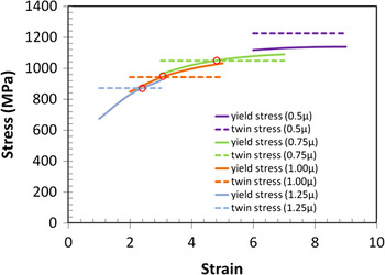
To confirm this, we plotted (see Fig. 12) the stresses required for twin formation and that for slip-dislocations for different shear strain values and used the strain rate found for sample b-high, i.e., 3300/s. We also ensured that we calculated the temperature for each combination of shear strain and strain rate considered in this plot using our iterative approach, instead of using a constant temperature as used in the plots in Ref. 41. This is crucial because the stress required for slip is given byReference Meyers, Voehringer, Chen, Ankem and Pande41

Stresses required for twin formation and slip dislocation and their transition point as a function of shear strain, for various initial grain sizes. The solid lines describe the stress required for yielding and the dashed lines describe the stress required for twinning for a given initial grain size. The circles mark the transition point from slip dislocation to twin formation. (Strain rate = 4500 s−1, same as that for sample b-high.)

where σG = 46.5 MPa, C 2 = 890 MPa, C 3 = 0.28 × 10⁻³ K−1, C 4 = 1.15 × 10⁻⁴ K−1, n = 0.5, and k s = 5 MPa.mm1/2. And, this contains a strong thermal component, which in our thermomechanically coupled machining framework varies with shear strain and strain rate and hence needs to be explicitly considered. Because the twin formation is an athermal process, it was plotted as a horizontal line in Fig. 12 depending only on the grain size with a grain size dependent twinning stress given byReference Meyers, Voehringer, Chen, Ankem and Pande41

where σ0T = 300 MPa and k t = 21.6 MPa.mm1/2. The stress values for yielding and twinning were found to be strongly dependent on the grain size; hence, we drew plots for various initial grain sizes varying from 1.25 to 0.5 μ (see Fig. 12). We observed a grain size dependent stress for thermally activated slip, which is generally smaller than the stress required for twinning at the smaller shear strain levels. As the shear strain values increase, we found a transition point beyond which twinning stress becomes smaller than the stress for slip and under these conditions, twinning can become feasible.
In chip formation by machining, microstructure refinement occurs gradually across the deformation zone wherein the microcrystalline material is transformed into a nanostructured material in a single deformation pass. It has been shown that the deformation zone where this transformation occurs is fan-shaped wherein the material is incrementally subjected to increasing levels of shear strain.Reference Lee, Hwang, Ravi Shankar, Chandrasekar and Compton22 It has also been demonstrated that in the initial parts of this fan-shaped deformation zone, the strain rates are smaller and the strain rates become progressively more intense.
In the initial parts of the fan-shaped deformation zone, the accumulated shear strain values are smaller and the level of refinement of the microstructure is also expected to be marginal. In this early stage of deformation, suppose the microstructure was already refined to a grain size of 0.5 μm, no amount of shear strain can result in twin formation (Fig. 12). However, if the grain sizes in the initial sections of the deformation zone are only refined to say ∼1.0 μm in size, then from Fig. 12 only a shear strain close to 3.2 is required to produce twins. Now, past the initial marginal levels of deformation, the progressive straining in the b-high sample can certainly reach these levels of shear strain in the more intense regions of the deformation zone where the strain rates are also much higher, thus enabling the transition from slip to twinning in accordance with the calculation illustrated in Fig. 12. In our earlier work, we have shown that sample condition b-high results in bimodal grain size distribution and a number of grains that are greater than 1.0 μm were observed in the chip microstructure. It is plausible that twinning occurred in the larger grains.Reference Shekhar, Cai, Wang and Shankar12 Additionally, it is likely that the twins also contribute to the increased strength in the b-high sample.
V. CONCLUSIONS
Chip formation in machining was used to subject Cu to an array of large plastic shear strains at a range of strain rates with an objective of understanding the effect of strain rate on the stored energy of the system and its microstructure. The resulting materials were found to possess stored energies that were found to be a function of the in situ dynamic heating that occurs in the deformation zone as an outcome of the applied shear strain and strain rate. Samples that experienced low temperature rise were found to lie in the first stage of recovery, which resulted in nominal change in microstructure and stored energy. The second stage of recovery was found to start around 360 K and samples in this stage were characterized by formation of cell walls and subgrain boundaries with a slight decrease in stored energy. The third stage of the recovery was found to start near 480 K and was characterized by grain growth for samples very close to this temperature while those subjected to a much higher temperature were found to show signs of complete recovery or recrystallization. The b-high sample, which lies near the end of stage-II retained its hardness even though the samples just into stage-III showed substantial softening. This was rationalized by the presence of twins along with the dislocation structures, which can also contribute to the higher strength in this sample condition.
ACKNOWLEDGMENTS
We would like to acknowledge support from the National Science Foundation (Award Nos. 0826010, 0856626, and 0927410) and the Nuclear Regulatory Commission (Faculty Development Grant). We also thank the Department of Mechanical Engineering and Materials Science for the provision of access to the electron microscopy instrumentation and for assistance with the execution of this part of our research.