I. INTRODUCTION
Microstrip antennas are earning major consideration for modern wireless communication due to their several advantages like low profile, light weight, easy fabrication, and MMIC (Monolithic Microwave Integrated Circuit) compatibility [Reference Garg, Bhartia, Bahl and Ittipiboon1, Reference Lo, Solomon and Richards2]. With the rapid development of wireless communication, modern transceiver systems need compact multiband antenna with excellent radiation characteristics. These antenna acts as an alternative for two or more separate antennas thus miniaturizing operating equipments. Several designs have been proposed as multiband antennas [Reference Liu, Ku and Yang3–Reference Mehdipour, Sebak, Trueman and Denidni7]. A design of the band-rejected function has been proposed by inserting the strips on a wideband antenna [Reference Chen and Ku4]. A trapezoidal ground plane also has been used for the WLAN/WiMAX applications [Reference Thomas and Sreenivasan5]. Multiband has been achieved using defected ground structure (DGS) [Reference Liu, Ku and Yang3–Reference Pei, Wang, Gao and Leng6]. Triple band has been achieved in monopole microstrip antenna using DGS [Reference Liu, Wu and Dai8]; however, it shows a quite high level of cross-polarization. DGS has been gained a lot of attraction of researchers for improving the deficiencies of conventional microstrip patch antenna (MPA), i.e. narrow bandwidth, single operating frequency, low gain, cross-polarized radiation, etc. [Reference Guha, Biswas and Antar9–Reference Caloz, Okabe, Iwai and Itoh19]. The cross-polarized radiation has been theoretically studied in [Reference Guha, Biswas and Antar9–Reference Guha, Kumar and Pal10]. The suppression of cross-polarized radiations has been reported using DGS [Reference Guha, Biswas and Antar9–Reference Khandelwal, Kanaujia, Dwari, Kumar and Gautam11]. A suppression of 5 dB in cross-polarization level has been achieved using dot shaped defects in ground plane [Reference Guha, Biswas and Antar9], and improved to the value of 10–12 dB using arc-shaped DGS [Reference Guha, Kumar and Pal10]. Theoretical analysis has been reported for the microstrip-line fed DGS antenna and isolation of 35 dB is achieved between co-polar and cross-polarization level [Reference Khandelwal, Kanaujia, Dwari, Kumar and Gautam11].
Latest communication devices should be versatile thus requires circularly polarized microstrip antennas. Circularly polarized antenna provides a powerful modulation scheme in active microwave systems [Reference Godara20, Reference Vaughan and Andersen21]. Circular polarization (CP) also combats multipath fading by introducing polarization diversity in radio propagation environment [Reference Skriverik, Zurcher, Staub and Mosig22] Single feed cross slot loaded circularly polarized compact microstrip antenna has been proposed [Reference Kumar, Kanaujia, Sharma, Khandelwal and Gautam23]; however, it operates at single frequency. Multiband microstrip antennas with CP also have been reported [Reference Hsieh, Chen and Wong24–Reference Falade, Rehman, Gao, Chen and Parini29].
In this paper, triple band compact MPA is proposed. Asymmetric slits are integrated to achieve the CP at first operating frequency. Further, ground plane is made defected to achieve the CP at other two frequencies. Three antenna structures with different ground shapes are proposed. Frequency dependent design equations for the defected ground plane are presented. Cross-polarization level is suppressed using DGS. The proposed structure is simulated and optimized using finite element method (FEM) based simulator Ansoft HFSS v.14 [30]. Antennas are fabricated on FR-4 epoxy substrate. The experimental results show good agreement with simulated results.
II. ANTENNA CONFIGURATION AND DESIGN
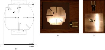
In this section, the designs of proposed antennas are described. Figure 1(a) shows the schematic of the proposed antenna with regular shaped ground plane and antenna is referred as Ant1. A circular patch of radius R e is combined with a square patch of dimension 2l s × 2l s . The centers of square and circle are coinciding and all four corners of the square are circularly truncated with arc of radius S. Circular patch is further truncated with two rectangles by the distance of w from horizontal sides of the square. Further, six slits of width w x are embedded in the structure. l x , ly , and l d is the length of the horizontal, vertical, and diagonal slits. Antenna is fed with a coaxial probe at the location of A. Ant1 has regular ground plane of the 46 × 46 mm2.
Structure of the proposed antenna Ant1 (without DGS); (a) schematic, (b) top view, (c) bottom view.

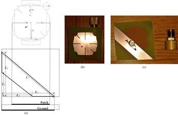
Further, same patch is proposed with a DGS and a trapezoidal shaped ground plane is used with coaxial probe feed. The proposed structure with trapezoidal shaped ground plane is referred as Ant2. The schematic of the Ant2 is shown in Fig. 2(a). The inclined length of trapezoidal is (L 2−L 1) and trapezoidal ground is located at the position of L 1 from the left-bottom corner of the substrate. The length (L 2−L 1) is taken as the quarter wavelength at third resonant frequency of Ant2.
 $$({L_2}\, - \; {L_1}) = \; \displaystyle{{{{\rm \lambda} _{32}}} \over 4} = \displaystyle{c \over {4.{f_{32}}}}\;,$$
where, c, λ 32, and f 32 are the speed of light in free space, wavelength, and third resonant frequency of Ant2, respectively.
Structure of the proposed antenna Ant2 (with trapezoidal shaped DGS); (a) schematic, (b) top view of fabricated Ant2, (c) bottom view of fabricated Ant2.

The bigger parallel length of trapezoidal ground (
 ${L_3} = {L_2}\sqrt 2 $
) is taken same as the wavelength at third resonant frequency.
 $${L_3} = \; {{\rm \lambda} _{32}} = \displaystyle{c \over {{f_{32}}}} = {L_2}\sqrt 2.$$
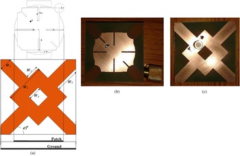
Further, same patch is proposed with deferent shaped DGS and antenna is referred as Ant3. The schematic of Ant3 is shown in Fig. 3(a). A square ring with cross-rectangular strips is used as ground plane and rotated at an angle of 450. The dimension of outer square of square ring is W 3 × W 3. A square slot of dimension W 4 × W 4 is integrated at the center of the square. Four strips of width W 1 is attached with square ring at an angle of 450 and placed with a distance W 2 from the corner of square ring. The length W 5 and W 4 is taken as the multiple of quarter wavelength at second resonance of Ant3.
 $${W_5} = \displaystyle{{{{\rm \lambda} _{23}}} \over 8} = \displaystyle{c \over {8.{f_{23}}}}\;. $$
 $${W_4} = \displaystyle{{{W_5}} \over 2} = \displaystyle{{{{\rm \lambda} _{23}}} \over {16}} = \displaystyle{c \over {16.{f_{23}}}}\;. $$
Structure of the proposed antenna Ant3 (with DGS); (a) schematic, (b) top view of fabricated Ant3, (c) bottom view of fabricated Ant3.

The radius of circular patch R e is determined as [Reference Garg, Bhartia, Bahl and Ittipiboon1]
 $${R_e} = \; \displaystyle{F \over {{{\left\{ {1\; + \; \displaystyle{{50h} \over {\pi {\varepsilon _r}F}}\left[ {\ln \left( {\displaystyle{{\pi F} \over {50h}}} \right) + \; 1.7726} \right]} \right\}}^{1/2}}}}\;, $$
where, h and ε r is the thickness and dielectric constant of the substrate respectively. And F is
 $$F = \; \displaystyle{{8.791 \times {{10}^9}} \over {{f_d}\sqrt {{\varepsilon _r}}}},$$
where, f d is the designing frequency of the structure.
The dimension of the square patch is calculated as [Reference Garg, Bhartia, Bahl and Ittipiboon1]
 $$2.{l_s} = \; \displaystyle{{\rm \lambda} \over 2} = \displaystyle{c \over {{f_d}\sqrt {{\varepsilon _r}}}}, $$
where, c is the speed of light in free space. The designing frequency f d is considered as 2.4 GHz for both the circular and square patch.
III. RESULTS AND DISCUSSION
A FR-4 epoxy substrate of dimension 46 × 46 × 1.6 mm3 is used to fabricate all the three antennas. Fabrication is done by standard photolithography process. The dielectric constant ε r , loss tangent tanδ, and height h of the substrate are 4.4, 0.002, and 1.6 mm, respectively. The detailed dimensions of proposed structures are listed in Table 1. The fabricated antennas are shown in Figs 1, 2, and 3. A 50-Ω SMA connector is used to feed the structure. The proposed antennas are analyzed using Ansoft HFSS v.14 [30] based on FEM.
Design specifications.

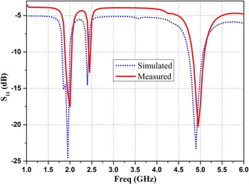
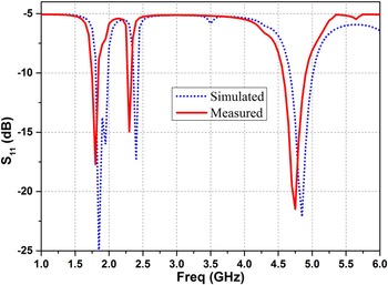
The return loss of the fabricated antennas is measured on Agilent™ Network Analyzer PNA-L Series. The S 11 variation with frequency of Ant1, Ant2, and Ant3 are shown in Figs 4, 5, and 6, respectively. By integrating the slits with combined shape of circular and square patch, the current path of the patch is increased and Ant1 resonates at frequencies 1.95, 2.4, and 4.9 GHz. The return loss level of Ant1 at these frequencies is 24.53, 14.54, and 23.25 dB, respectively. Small frequency ratio f 2/f 1 of the value of 1.23 is achieved. A compactness of 18.75% with triple band characteristics is achieved with respect to design frequency. Ant2 resonates at frequencies 1.85, 2.4, and 4.85 GHz. Compactness is further improved to the value of 22.91%. The return loss level of Ant2 at these frequencies is 25.36, 17.38, and 22.12 dB, respectively. The return loss level of Ant3 is 23.56, 15.55, and 22.71 dB at frequencies 1.95, 2.4, and 4.85 GHz, respectively.
Simulated and measured S11 variations with frequency of Ant1.

Simulated and measured S11 variations with frequency of Ant2.

Simulated and measured S11 variations with frequency of Ant3.

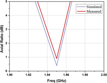
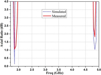
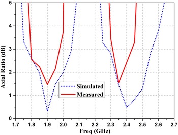
Ant1 shows the right-hand circularly polarized (RHCP) characteristics at frequency 1.95 GHz. Figure 7 shows the axial ratio plot with resonant frequency of Ant1. The axial ratio of the Ant1 at 1.95 GHz is measured as 0.89 dB. Ant2 shows the RHCP characteristics at 1.85 and 4.85 GHz. The length L 3 and the distance (L 2−L 1) between parallel lines of the trapezoidal shaped ground plane are taken as the wavelength and quarter wavelength at frequency 4.85 GHz, respectively. These parameters of Ant2 are responsible for the CP at frequency 4.85 GHz. Figure 8 shows the axial ratio plot with resonant frequency of Ant2. The axial ratio of the Ant2 is measured as 1.05, and 1.82 dB at the frequencies 1.85 and 4.85 GHz, respectively. Figure 9 shows the axial ratio plot with resonant frequency of Ant3. Ant3 shows the RHCP characteristics at frequencies of 1.95 and 2.4 GHz. The length W 5 and W 4 of the ground plane of Ant3 is taken as λ/8 and λ/16 at frequency 2.4 GHz respectively. Thus, results in CP characteristics at frequency 2.4 GHz. The axial ratio of the Ant3 is measured as 1.46, and 1.54 dB at the frequencies 1.95 and 2.4 GHz, respectively.
Simulated and measured Axial Ratio variations with frequency of Ant1 (without DGS).

Simulated and measured Axial Ratio variations with frequency of Ant2 (with trapezoidal shaped DGS).

Simulated and measured Axial Ratio variations with frequency of Ant3 (with DGS).

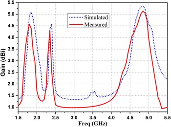
Figures 10, 11, and 12 shows the gain characteristics of the proposed Ant1, Ant2, and Ant3 respectively. All three antennas show good radiation characteristics. Ant1 shows the gain of 5.53, 4.54, and 4.25 dBi at frequencies 1.95, 2.4, and 4.9 GHz, respectively. Ant2 shows the gain of 5.08, 4.58, and 5.32 dBi at frequencies 1.85, 2.4, and 4.85 GHz, respectively. Ant3 shows the gain of 5.42, 5.25, and 5.21 dBi at frequencies 1.95, 2.4, and 4.85 GHz, respectively. Tables 2, 3, and 4 give a comparative data of Ant1, Ant2, and Ant3.
Simulated and measured Antenna Gain variations with frequency of Ant1.

Simulated and measured Antenna Gain variations with frequency of Ant2.

Simulated and measured Antenna Gain variations with frequency of Ant3.

Result analysis of Ant1.

Result analysis of Ant2.

Result analysis of Ant3.

Figures 13(a) and 13(b) show the co-polar and cross-polar radiation pattern of Ant1 (without DGS) at resonant frequency 1.95 GHz in E-plane and H-plane, respectively. The Ant1 shows RHCP behavior at frequency 1.95 GHz and cross-polarization is considered as left-hand circularly polarized (LHCP). The LHCP level of Ant1 (without DGS) is about −16 and −15 dB at frequency 1.95 GHz in E-plane and H-plane, respectively. The co-polar and cross-polar radiation pattern of Ant1 (without DGS) at frequency 4.9 GHz in E-plane and H-plane is shown in Figs 14(a) and 14(b), respectively.
Simulated and measured co-polar and cross-polar radiation pattern of Ant1 (without DGS) at frequency 1.95 GHz, (a) E-plane, (b) H-plane.

Simulated and measured co-polar and cross-polar radiation pattern of Ant1 (without DGS) at frequency 4.9 GHz, (a) E-plane, (b) H-plane.

The cross-polarization level of Ant1 at frequency 4.9 GHz is about −24 dB in both E-plane and H-plane shown in Figs 14(a) and 14(b), respectively. The radiation patterns of all three antennas at frequency 2.4 GHz are almost identical to the radiation patterns at third resonant frequency correspondingly. Thus, radiation patterns at frequency 2.4 GHz are not shown in this paper.
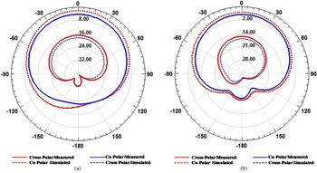
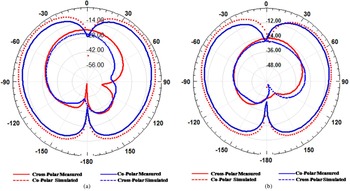
The co-polar and cross-polar radiation pattern of Ant2 (with trapezoidal shaped ground plane) at resonant frequencies 1.85 and 4.85 GHz is shown in Figs 15 and 16, respectively. By using trapezoidal shaped defected ground plane, the cross-polarization level is suppressed to the value of −24 dB in both E-plane and H-plane at resonant frequency 1.85 GHz shown in Figs 15(a) and 15(b), respectively. The cross-polarization level of Ant2 at frequency 4.85 GHz is about −28 dB in both E-plane and H-plane shown in Figs 16(a) and 16(b), respectively.
Simulated and measured co-polar and cross-polar radiation pattern of Ant2 (with trapezoidal shaped DGS) at frequency 1.85 GHz, (a) E-plane, (b) H-plane.

Simulated and measured co-polar and cross-polar radiation pattern of Ant2 (with trapezoidal shaped DGS) at frequency 4.85 GHz, (a) E-plane, (b) H-plane.

The co-polar and cross-polar radiation pattern of Ant3 at resonant frequencies 1.95 and 4.85 GHz is shown in Figs 17 and 18, respectively. The cross-polarization level is further suppressed to the value of −28 dB in both E-plane and H-plane at resonant frequency 1.95 GHz. At frequency 4.85 GHz the cross-polarization level of Ant3 is suppressed to the value of −38 dB in both E-plane and H-plane, shown in Figs 18(a) and 18(b), respectively.
Simulated and measured co-polar and cross-polar radiation pattern of Ant3 (with DGS) at frequency 1.95 GHz, (a) E-plane, (b) H-plane.

Simulated and measured co-polar and cross-polar radiation pattern of Ant3 (with DGS) at frequency 4.85 GHz, (a) E-plane, (b) H-plane.

IV. CONCLUSION
Asymmetric slits loaded and corner truncated irregular shaped MPA with and without DGS is designed and fabricated. By integrating the slits compactness of 18.75% with triple band characteristics and small frequency ratio f 2/f 1 of the value of 1.23 is achieved. Ant1 without DGS resonates at three frequencies 1.95, 2.4, and 4.9 GHz with antenna gain of 5.53, 4.54, and 4.25 dBi respectively. Ant1 shows RHCP at frequency 1.95 GHz. Further, same patch is used with trapezoidal shaped DGS and Ant2 resonates at 1.85, 2.4, and 4.85 GHz with antenna gain of 5.08, 4.58, and 5.32 dBi, respectively. Compactness is further improved to the value of 22.91% and antenna shows the RHCP at frequencies 1.85 and 4.85 GHz. By using trapezoidal shaped DGS cross-polarization level is suppressed to the value of −24 and −28 dB in both planes at resonant frequencies 1.85 and 4.85 GHz, respectively. Further, same patch is used with different shaped DGS and Ant3 shows resonance at frequencies 1.95, 2.4, and 4.85 GHz with antenna gain of 5.42, 5.25, and 5.21 dBi, respectively. Ant3 shows RHCP characteristics at frequencies 1.95 and 2.4 GHz with the axial ratio of the value of 1.46 and 1.54 dB respectively. Cross-polarization level is further suppressed to the value of −28 and −38 dB in both planes at resonant frequencies 1.95 and 4.85 GHz, respectively. Thus, all three proposed antennas are suitable for modern wireless applications due to their compact size, minimum return loss level, good antenna gain, and circular polarization characteristics with suppressed cross-polarization level.
 Mukesh Kumar Khandelwal received his B. Tech. degree in Electronics and Communication Engineering in 2010 and M. Tech. degree in Digital Communication in 2012 from GGSIP University, Delhi, India. He has published seven research papers in referred International Journals and two in International conferences. His current research interests focus on microstrip antennas, defected ground structure, and microwave component.
 Binod Kumar Kanaujia presently is working as Associate Professor in Department of Electronics and Communication Engineering in Ambedkar Institute of Advanced Communication Technologies and Research, (formerly Ambedkar Institute of Technology) Geeta Colony, Delhi and served on various key portfolios, i.e. Head of Department of E&CE from February 21, 2008 to August 05, 2010 and August 17, 2012 to June 5, 2014. He has also served as the Head of office of this institute since 09 Aug 2008 to 03 May 2013 and continuously exploring for good administration in the institute. In-charge Central Library from March 2008 to Aug 2010. He under took to modernize and upgrade the Library with the introduction of fully automatic book issue and receiving, on-line journal, on-line retrieval of catalogue of the Library and establishment of E-Library. Dr. Kanujia joined this institute as Assistant Professor, Electronics and Communication Engineering in Jan 2008 through selection by Union Public Service Commission New Delhi. Before joining this institute he has served in the M. J. P Rohilkhand University, Bareilly as Reader from February 26, 2005 to January 30, 2008 and Lecturer from June 25, 1996 to February 25, 2005 in the Department of Electronics and Communication Engineering and also served as the Head of Department E&CE from July 25, 2006 to January 30, 2008. He has been an active member of Academic Council and Executive Council of the M J P Rohilkhand University and played a vital role in the academic reforms. Prior to his career in the academics, Dr. Kanaujia has worked as Executive Engineer in the R&D division of M/s UPTRON India Ltd. Dr. Kanaujia has completed B. Tech. in Electronics Engineering from KNIT Sultanpur, India in 1994. He did M. Tech. and Ph.D. in 1998 and 2004 from Electronics Engineering Department IIT BHU Varanasi, respectively. He has been awarded Junior Research fellow by UGC Delhi in the year 2001–02 for his outstanding work in his field. His has keen research interest in design and modeling of Microstrip Antenna, Dielectric Resonator Antenna, Left Handed Metamaterial Microstrip Antenna, Shorted Microstrip Antenna, Ultra Wide Band Antennas, Reconfigurable and Circular Polarized Antenna for Wireless Communication, etc. He has been credited to publish more than 105 research papers with more than 200 citations with h-index 10 in peer-reviewed journals and conferences. He has already supervised 45 M. Tech. and 03 Ph.D. Research scholars for award of Post Graduate (M. Tech.) and Doctoral degree, respectively, in the area of Microwave Engineering. He is presently supervising six research scholars for Ph.D. degree. He is reviewer for research papers of several International Journals of repute, i.e. IET Microwaves, Antennas and Propagation (UK), IEEE Antenna and Wireless Propagation Letters (USA), Wireless Personal Communications (springer), Journal of Electromagnetic Wave and Application, Indian Journal of Radio and Space Physics (India), IETE Technical Review, International Journal of Electronics (UK), International Journal of Engineering Science, IEEE Transaction on Antenna and Propagation (USA), International Journal of Electronics and Communication Elsevier, International Journal of Microwave and Wireless Technologies (USA), etc. Dr. Kanaujia has executed more than 04 research projects successfully sponsored by DRDO, DST, AICTE, ISRO agencies of Government of India. He is member of several academic and professional bodies, i.e. Member of IEEE, Life members of the Institution of Engineers (India), Indian Society for Technical Education and the Institute of Electronics and Telecommunication Engineers of India.
 Santanu Dwari was born in Howrah, West Bengal, India. He received his B. Tech and M. Tech degrees in Radio Physics and Electronics from University of Calcutta, Kolkata, West Bengal, India in the year of 2000 and 2002, respectively, and Ph.D. degree from Indian Institute of Technology, Kharagpur, West Bengal, India in the year of 2009. He joined Indian School of Mines, Dhanbad, Jharkhand, India in 2008 where he is currently an Assistant Professor in the Department of Electronics Engineering. He has published 21 research papers in referred International Journals and conferences. He is carrying out two sponsored research project as Principal Investigator. His research interest includes Antennas, RF planar circuits, and Computational Electromagnetics.
 Sachin Kumar received his B. Tech. degree in Electronics and Communication Engineering in 2009 and M. Tech degree in Digital Communication in 2011 from Ambedkar Institute of Technology, Delhi, India. Currently, he is working toward his Ph.D. Degree in the field of Microwave Engineering from GGSIP University, Delhi, India. His current research interests focus on microstrip antennas, as well as wireless communication.
 A. K. Gautam was born in NOIDA, Uttar Pradesh, India. He received the B.E. degree in Electronics and Communication Engineering from Kumaon Engineering College, Almora, India and the Ph.D. degree in Electronic Engineering from Indian Institute of Technology, Banaras Hindu University, Varanasi, India, in 1999 and 2007, respectively. He joined the Department of Electronics and Communication Engineering, G B Pant Engineering College, Pauri Garhwal, India, in 2000, as an Assistant Professor and he has been an Associate Professor there since 2009. He is an active member of Board of study, Academic council and many other academic committees of GBPEC, Pauri. He is also member of BOS of HNB Garhwal Central University, INDIA and Uttarakhand Technical University, Dehradun, INDIA. He is nominated as Nodal Officer, TSP and SCSP Grants by Government of Uttarakhand and executed several projects under these grants. He has supervised 15 M. Tech. and 01 Ph.D. Thesis and currently supervising 09 Ph.D. theses in the area of microstrip antenna. He is the author/coauthor of more than 60 research papers published in the refereed international journals and conferences like IEEE, Microwave and optical Technology Letters, Springer, etc. He is the author of the 12 books in the field of Electronics Engineering in the field of Digital Electronics, Antenna and Microwave Engineering. He is a member of IEEE (USA) and many other technical societies. He is also in reviewers panel of IEEE, Transaction on Antenna and Propagation, IET Microwaves, Antennas and Propagation, Personal and wireless communication, Springer, International Journal of Electronics, International Journal of Antenna and Propagation. His main research interests are in design and modeling of active microstrip antenna, microstrip antennas with defected ground structure, ultra wide bandwidth antennas, and reconfigurable antennas, reconfiguration antenna array, circular polarized antenna, etc.