1 Introduction
Our study concerns the large Reynolds number fate of the magneto-rotational instability (MRI), which could destabilise hydrodynamically stable rotating flows by an imposed uniform magnetic field in the direction of rotation. The instability was first pointed out by Velikhov (Reference Velikhov1959) and Chandrasekhar (Reference Chandrasekhar1960), who proposed the exceptionally simple stability condition: the azimuthal background flow
 $V_{b}(r)$
is stable if
 $$\begin{eqnarray}\displaystyle \frac{\text{d}(r^{-1}V_{b})^{2}}{\text{d}r}>0\quad \text{for all }r, & & \displaystyle\end{eqnarray}$$
namely the modulus of the angular velocity of the flow increases outwardly. That stability condition for magnetised flows is more restrictive than the stability condition for purely hydrodynamic flows given earlier by Rayleigh (Reference Rayleigh1917) that the flow is stable if
 $$\begin{eqnarray}\displaystyle \frac{\text{d}(rV_{b})^{2}}{\text{d}r}>0\quad \text{for all }r, & & \displaystyle\end{eqnarray}$$
namely the modulus of the angular momentum of the flow increases outwardly. Decades later Balbus & Hawley (Reference Balbus and Hawley1991) spotted that the MRI could destabilise astrophysical flows under Kepler’s law, which is stable according to (1.2). Their discovery surprised other astrophysicists, as turbulence triggered by the instability might explain the unknown angular momentum loss in accreting astrophysical objects.
Since Taylor (Reference Taylor1923), Taylor–Couette flow has widely been selected as the archetype model for instabilities appearing in rotating flows because of its simplicity and experimental feasibility. The effect of imposed magnetic fields on the stability of the flow has been intensively studied by numerous researchers, as summarised in the recent review by Rüdiger et al. (Reference Rüdiger, Gellert, Hollerbach, Schultz and Stefani2018a ). An advantage of using Taylor–Couette flow to study the MRI is that the motion of the independently rotating cylinders can be used to control the laminar flow profile to be within the stable or unstable regimes in terms of (1.1) or (1.2). The laminar circular Couette flow is known as one of the simplest Navier–Stokes solutions
 $$\begin{eqnarray}\displaystyle V_{b}(r)=R_{s}r+R_{p}/r, & & \displaystyle\end{eqnarray}$$
where the constants
 $R_{s}$
and
 $R_{p}$
are fixed by the cylinder speeds and correspond to the intensity of the solid-body rotation part and the potential flow part, respectively. The sign of those constants are useful to judge the stability of the flow, since the inequalities appearing in (1.1) and (1.2) become
 $-V_{b}R_{p}>0$
and
 $V_{b}R_{s}>0$
, respectively. The gap between those stability conditions, called the anticyclonic regime (
 $R_{s}R_{p}>0$
), is the most important in astrophysics, at it contains the Kepler rotation (more precisely, in Taylor–Couette flow we can only realise quasi-Kepler rotation (2.7)).
Both of the stability conditions (1.1) and (1.2) are derived for ideal, axisymmetric perturbations and only represent sufficient conditions for stability. Given specific flow configurations, more accurate stability conditions can be found by numerical computations of linearised viscous resistive magneto-hydrodynamic (MHD) equations. The earliest computations of magnetised Taylor–Couette flow can be found in Chandrasekhar (Reference Chandrasekhar1953, Reference Chandrasekhar1961), where the inductionless approximation was used to simplify the problem by taking the limit of vanishing magnetic Prandtl number. Kurzweg (Reference Kurzweg1963) solved the finite magnetic Prandtl number problem for the first time, but with an oversimplified flow geometry and boundary conditions. The most complete numerical study at that time was due to Roberts (Reference Roberts1964), who proposed realistic boundary conditions and removed the previously used axisymmetric assumption on the perturbations. The aim of those early computational studies was to explain experimentally observed suppression of the Rayleigh’s hydrodynamic instability against the imposed axial uniform magnetic field (Donnelly & Ozima Reference Donnelly and Ozima1960, Reference Donnelly and Ozima1962; Donnelly & Caldwell Reference Donnelly and Caldwell1964; Brahme Reference Brahme1970). The focus of experimental studies then shifted to the Rayleigh stable regime after Balbus & Hawley (Reference Balbus and Hawley1991), but the instability has never been observed for quasi-Kepler rotation. A decade later Goodman & Ji (Reference Goodman and Ji2002) uncovered the reason why it is difficult to observe the MRI experimentally. For the anticyclonic regime the critical magnetic Reynolds number tends to a constant for small magnetic Prandtl numbers
 $P$
. This means that the critical Reynolds number of
 $O(P^{-1})$
should be very large, as the value of
 $P$
is typically
 $10^{-5}\sim 10^{-7}$
for the liquid metals used in experiments.
Nowadays the instability studied by Velikhov (Reference Velikhov1959) and Chandrasekhar (Reference Chandrasekhar1960) is called standard MRI because more recently Hollerbach & Rüdiger (Reference Hollerbach and Rüdiger2005) showed that an additional azimuthal component of the external magnetic field dramatically reduces the critical Reynolds number to
 $O(P^{0})$
; see Knobloch (Reference Knobloch1992) also. This new type of instability, called helical MRI, indeed led to the experimental confirmation of the MRI (Rüdiger et al.
Reference Rüdiger, Hollerbach, Stefani, Gundrum, Gerbeth and Rosner2006; Stefani et al.
Reference Stefani, Gundrum, Gerbeth, Rüdiger, Schultz, Szklarski and Hollerbach2006, Reference Stefani, Gundrum, Gerbeth, Rüdiger, Szklarski and Hollerbach2007).
Parallel to those above global studies, so-called local stability analysis has also been used as a conventional tool to explore the parameter space. The key assumption used in the local analysis that the perturbation is locally periodic in all three directions enables us to reduce the stability problem to a single algebraic equation. The local analysis is sometimes referred to as Wentzel–Kramers–Brillouin (WKB) analysis, perhaps because the algebraic stability equation derived in the local analysis is equivalent to the eikonal equation governing the WKB phase. However, in order to construct a rational global approximation, the solutions at each local station must be connected through the WKB amplitude equation at higher order. Furthermore, usually the asymptotic system is not closed unless the WKB solution is matched to the near-wall boundary layer solutions. In short, the local analysis is not mathematically equivalent to the WKB analysis, which serves as a rational approximation for global short wavelength modes. Thus, there is occasionally a controversial disagreement between the local and global studies, as seen in the helical MRI (Liu et al. Reference Liu, Goodman, Herron and Ji2006; Rüdiger & Hollerbach Reference Rüdiger and Hollerbach2007; Priede Reference Priede2011). Nevertheless, for the standard MRI the local results produce the stability boundary that is not too far from the global results (Ji, Goodman & Kageyama Reference Ji, Goodman and Kageyama2001). In much the same spirit nonlinear local computations that use a periodic shearing box have been intensively performed in astrophysics; see Brandenburg et al. (Reference Brandenburg, Nordlund, Stein and Torkelsson1995), Hawley, Gammie & Balbus (Reference Hawley, Gammie and Balbus1995).
The aim of this paper is to find accurate self-consistent approximations of the neutral curve assuming large Reynolds numbers of astrophysical importance. The matched asymptotic expansion on which our analyses are based is the mathematically rational version of the flow scaling analysis, and has some similarity to the small magnetic Prandtl number analysis of the neutral curve (Chandrasekhar Reference Chandrasekhar1953, Reference Chandrasekhar1961; Goodman & Ji Reference Goodman and Ji2002; Willis & Barenghi Reference Willis and Barenghi2002; Rüdiger, Schultz & Shalybkov Reference Rüdiger, Schultz and Shalybkov2003; Hollerbach & Rüdiger Reference Hollerbach and Rüdiger2005). However, unlike the previous studies, here we fix the magnetic Prandtl number
 $P$
as an
 $O(1)$
quantity and choose the inverse of the Reynolds number as the intrinsic small parameter of the approximation; in fact,
 $P$
is a constant no matter how small it is, because it should be fixed by the material property of the fluid. For purely hydrodynamic Taylor–Couette flow, large Reynolds number analysis successfully produced good approximations of the neutral curve; see Deguchi (Reference Deguchi2016).
The conclusions drawn in many previous asymptotic analyses is, somewhat counterintuitively, the largeness of the Reynolds number does not mean that the diffusivity is always negligible. As a result, the ideal analysis sometimes produces an outcome that contradicts the large Reynolds number limit of the full equations. For example, it is widely known that at least one inflection point of the base flow is necessary to destabilise ideal shear flows, but in reality the Tollmien–Schlichting wave type of instability occurs without any inflection point (see Lin Reference Lin1955; Drazin & Reid Reference Drazin and Reid1981); recently Deguchi (Reference Deguchi2017) found similar viscous destabilisation in Rayleigh stable cyclonic Taylor–Couette flow. The most famous paradoxical ideal result in the MRI might be the so-called Velikhov–Chandrasekhar paradox, namely the zero external magnetic field limit of the Velikhov–Chandrasekhar condition (1.1) does not coincide with the purely hydrodynamic result (1.2). In fact, the ideal problem has a discontinuous change of instability there (Kirillov, Pelinovsky & Schneider Reference Kirillov, Pelinovsky and Schneider2011). The paradox has then been resolved by Kirillov & Stefani (Reference Kirillov and Stefani2011) within the framework of the local analysis of the dissipative problem, but not yet for the global context.
In the next section we shall formulate our problem based on the viscous resistive MHD equations. Section 3 compares the ideal and full numerical results. We begin the comparison from the local analysis to show that the ideal result by Velikhov (Reference Velikhov1959) indeed gives a good approximation for some cases. The results are then extended to narrow and wide-gap Taylor–Couette flows. The stabilisation effect by the ideal analysis competes with the destabilisation effect of the hydrodynamic instability when the magnetic Prandtl number becomes relatively small, thereby leading to the breakdown of the ideal result. The reason for the breakdown is explained in § 4 using the asymptotic limit and by assuming a long wavelength perturbation. Section 5 concerns the asymptotic limit of the MRI, which appears at the Rayleigh stable region. The simple limiting stability criterion describes the smooth transition from Rayleigh’s condition (1.2) to the Velikhov–Chandrasekhar condition (1.1) with increasing the magnetic field from zero. Finally, in § 6, we conclude with a brief discussion.
2 Formulation of the problem
Consider the non-dimensional incompressible viscous resistive MHD equations
 $$\begin{eqnarray}\displaystyle & \displaystyle (\unicode[STIX]{x2202}_{t}+\unicode[STIX]{x1D735}\boldsymbol{\cdot }\boldsymbol{v})\boldsymbol{v}-(\boldsymbol{b}\boldsymbol{\cdot }\unicode[STIX]{x1D735})\boldsymbol{b}=-\unicode[STIX]{x1D735}q+\unicode[STIX]{x1D6FB}^{2}\boldsymbol{v}, & \displaystyle\end{eqnarray}$$
 $$\begin{eqnarray}\displaystyle & \displaystyle (\unicode[STIX]{x2202}_{t}+\unicode[STIX]{x1D735}\boldsymbol{\cdot }\boldsymbol{v})\boldsymbol{b}-(\boldsymbol{b}\boldsymbol{\cdot }\unicode[STIX]{x1D735})\boldsymbol{v}=P^{-1}\unicode[STIX]{x1D6FB}^{2}\boldsymbol{b}, & \displaystyle\end{eqnarray}$$
 $$\begin{eqnarray}\displaystyle & \displaystyle \unicode[STIX]{x1D735}\boldsymbol{\cdot }\boldsymbol{v}=0,\quad \unicode[STIX]{x1D735}\boldsymbol{\cdot }\boldsymbol{b}=0 & \displaystyle\end{eqnarray}$$
 $(r,\unicode[STIX]{x1D703},z)$
. Here we write the velocity vector as
 $\boldsymbol{v}=u\boldsymbol{e}_{r}+v\boldsymbol{e}_{\unicode[STIX]{x1D703}}+w\boldsymbol{e}_{z}$
, the magnetic vector as
 $\boldsymbol{b}=a\boldsymbol{e}_{r}+b\boldsymbol{e}_{\unicode[STIX]{x1D703}}+c\boldsymbol{e}_{z}$
and the total pressure as
 $q$
. The magnetic Prandtl number
 $P$
is the ratio of the kinematic viscosity to the magnetic diffusivity. Here we scale the magnetic field so that the pre-factor of the Lorentz force term
 $(\boldsymbol{b}\boldsymbol{\cdot }\unicode[STIX]{x1D735})\boldsymbol{b}$
in (2.1a
) is normalised. Also the normalised viscous term
 $\unicode[STIX]{x1D6FB}^{2}\boldsymbol{v}$
in the same equation means that our choice of the velocity scale is the viscous one, and hence the Reynolds numbers should appear in the base flow. The flow is assumed to be enclosed by two infinitely long co-axial cylinders placed at
 $r=r_{i}$
and
 $r=r_{o}$
, where
 $r_{o}>r_{i}$
. Our length scale is the half-gap of the cylinders, namely
 $r_{o}-r_{i}=2$
. Thus using the radius ratio
 $\unicode[STIX]{x1D702}=r_{i}/r_{o}$
, we can express the positions of the cylinders as
 $$\begin{eqnarray}\displaystyle r_{i}=\frac{2\unicode[STIX]{x1D702}}{1-\unicode[STIX]{x1D702}},\quad r_{o}=\frac{2}{1-\unicode[STIX]{x1D702}}. & & \displaystyle\end{eqnarray}$$
Throughout the paper we assume the flow to be axisymmetric.
Rotating the cylinder walls with constant angular speeds, the well-known Taylor–Couette flow is realised. We further apply a uniform axial magnetic field of non-dimensional magnitude
 $B_{0}$
to trigger the MRI. Note that we have to scale it by the magnetic Prandtl number to get the Hartmann and Lundquist numbers
 $$\begin{eqnarray}\displaystyle H=B_{0}P^{1/2},\quad S=B_{0}P, & & \displaystyle\end{eqnarray}$$
respectively. The base flow can be written as
 $$\begin{eqnarray}\displaystyle \boldsymbol{v}=V_{b}(r)\boldsymbol{e}_{\unicode[STIX]{x1D703}},\quad \boldsymbol{b}=B_{0}\boldsymbol{e}_{z}, & & \displaystyle\end{eqnarray}$$
where the laminar velocity field of the Taylor–Couette flow
 $V_{b}$
is the sum of the solid-body rotation part and the potential flow part as shown in (1.3). In order to satisfy
 $$\begin{eqnarray}\displaystyle V_{b}(r_{i})=R_{i},\quad V_{b}(r_{o})=R_{o}, & & \displaystyle\end{eqnarray}$$
we must set
 $$\begin{eqnarray}\displaystyle R_{s}=\frac{R_{o}-\unicode[STIX]{x1D702}R_{i}}{2(1+\unicode[STIX]{x1D702})},\quad R_{p}=\frac{\unicode[STIX]{x1D702}^{-1}R_{i}-R_{o}}{2(1+\unicode[STIX]{x1D702})}r_{i}^{2}. & & \displaystyle\end{eqnarray}$$
Here the Reynolds number
 $R_{i}/R_{o}$
is defined by the ratio of the inner/outer cylinder speed and the viscous velocity scale made by the kinematic viscosity of the fluid and the half-gap.
Kepler’s law states that the square of the period of the orbital motion should be proportional to
 $r^{3}$
. If we apply this condition for all streamlines then we have the base flow
 $V_{b}(r)\propto r^{-1/2}$
, which is never realisable as a base flow. Thus in Taylor–Couette flow studies Kepler’s law is only applied for the cylinders’ motion. The base flow in this case, satisfying
 $$\begin{eqnarray}\displaystyle R_{i}/R_{o}=\unicode[STIX]{x1D702}^{-1/2}, & & \displaystyle\end{eqnarray}$$
is called the quasi-Keplerian rotation. Note that elsewhere that terminology is also used in a somewhat wider sense, to include any rotating flow in which the inequality (1.2) is satisfied but the reverse of (1.1) is true.
The linear perturbation to the base flow can be expressed by normal modes so we write
 $$\begin{eqnarray}\displaystyle \boldsymbol{v}=V_{b}(r)\boldsymbol{e}_{\unicode[STIX]{x1D703}}+\widehat{\boldsymbol{v}}(r)\exp (\unicode[STIX]{x1D70E}t+\text{i}kz),\quad \boldsymbol{b}=B_{0}\boldsymbol{e}_{z}+\widehat{\boldsymbol{b}}(r)\exp (\unicode[STIX]{x1D70E}t+\text{i}kz), & & \displaystyle\end{eqnarray}$$
where
 $k$
,
 $\unicode[STIX]{x1D70E}$
are the axial wavenumber and the complex growth rate of the perturbation, respectively. Substituting (2.8) into (2.1) and linearising the equations gives
 $$\begin{eqnarray}\displaystyle & \displaystyle \left[\begin{array}{@{}c@{}}-2r^{-1}V_{b}v\\ r^{-1}(rV_{b})^{\prime }u\\ 0\end{array}\right]=-\left[\begin{array}{@{}c@{}}Dq\\ 0\\ \text{i}kq\end{array}\right]+\left[\begin{array}{@{}c@{}}(DD_{\ast }-k^{2}-\unicode[STIX]{x1D70E})u\\ (DD_{\ast }-k^{2}-\unicode[STIX]{x1D70E})v\\ (D_{\ast }D-k^{2}-\unicode[STIX]{x1D70E})w\end{array}\right]+\text{i}kB_{0}\left[\begin{array}{@{}c@{}}a\\ b\\ c\end{array}\right], & \displaystyle\end{eqnarray}$$
 $$\begin{eqnarray}\displaystyle & \displaystyle \left[\begin{array}{@{}c@{}}0\\ -r(r^{-1}V_{b})^{\prime }a\\ 0\end{array}\right]=P^{-1}\left[\begin{array}{@{}c@{}}(DD_{\ast }-k^{2}-\unicode[STIX]{x1D70E})a\\ (DD_{\ast }-k^{2}-\unicode[STIX]{x1D70E})b\\ (D_{\ast }D-k^{2}-\unicode[STIX]{x1D70E})c\end{array}\right]+\text{i}kB_{0}\left[\begin{array}{@{}c@{}}u\\ v\\ w\end{array}\right], & \displaystyle\end{eqnarray}$$
 $$\begin{eqnarray}\displaystyle & \displaystyle D_{\ast }u+\text{i}kw=0,\quad D_{\ast }a+\text{i}kc=0. & \displaystyle\end{eqnarray}$$
 $D=\unicode[STIX]{x2202}_{r},D_{\ast }=\unicode[STIX]{x2202}_{r}+1/r$
are the usual Chandrasekhar notations. Dropping all the diffusive terms (i.e. the terms proportional to
 $(DD_{\ast }-k^{2})$
or
 $(D_{\ast }D-k^{2})$
) from (2.9) and assuming
 $u$
vanishes on the walls, Chandrasekhar (Reference Chandrasekhar1960) derived the integral equation
 $$\begin{eqnarray}\displaystyle & & \displaystyle (\unicode[STIX]{x1D70E}^{2}+k^{2}B_{0}^{2})^{2}\int _{r_{i}}^{r_{o}}r(|D_{\ast }u|^{2}+k^{2}|u|^{2})\,\text{d}r\nonumber\\ \displaystyle & & \displaystyle +\,k^{2}\int _{r_{i}}^{r_{o}}\left(\unicode[STIX]{x1D70E}^{2}\frac{1}{r^{2}}\frac{\text{d}(rV_{b})^{2}}{\text{d}r}+k^{2}B_{0}^{2}r^{2}\frac{\text{d}(r^{-1}V_{b})^{2}}{\text{d}r}\right)|u|^{2}\,\text{d}r=0,\end{eqnarray}$$
where
 $\unicode[STIX]{x1D70E}^{2}$
should be real. The Velikhov–Chandrasekhar result follows by noting that if (1.1) holds then
 $\unicode[STIX]{x1D70E}^{2}<0$
and hence there is no instability for the ideal flow. (We also remark that if (1.2) holds and
 $B_{0}=0$
then
 $\unicode[STIX]{x1D70E}^{2}<0$
. Synge (Reference Synge1938) showed that this sufficient condition also holds for viscous axisymmetric linear perturbations.)
Now let us introduce the potentials satisfying
 $u=\text{i}k\unicode[STIX]{x1D719}$
,
 $w=-(r\unicode[STIX]{x1D719})^{\prime }/r$
,
 $a=\text{i}k\unicode[STIX]{x1D713}$
,
 $c=-(r\unicode[STIX]{x1D713})^{\prime }/r$
to transform (2.9) into the simpler form
 $$\begin{eqnarray}\displaystyle & \displaystyle (\unicode[STIX]{x1D70E}-\triangle )\triangle \unicode[STIX]{x1D719}-\text{i}kB_{0}\triangle \unicode[STIX]{x1D713}-\text{i}k(2R_{s}+2r^{-2}R_{p})v=0, & \displaystyle\end{eqnarray}$$
 $$\begin{eqnarray}\displaystyle & \displaystyle (\unicode[STIX]{x1D70E}-\triangle )v-\text{i}kB_{0}b+\text{i}k2R_{s}\unicode[STIX]{x1D719}=0, & \displaystyle\end{eqnarray}$$
 $$\begin{eqnarray}\displaystyle & \displaystyle (\unicode[STIX]{x1D70E}-P^{-1}\triangle )\unicode[STIX]{x1D713}-\text{i}kB_{0}\unicode[STIX]{x1D719}=0, & \displaystyle\end{eqnarray}$$
 $$\begin{eqnarray}\displaystyle & \displaystyle (\unicode[STIX]{x1D70E}-P^{-1}\triangle )b-\text{i}kB_{0}v+\text{i}k2r^{-2}R_{p}\unicode[STIX]{x1D713}=0, & \displaystyle\end{eqnarray}$$
 $\triangle =DD_{\ast }-k^{2}$
. The no-slip conditions on the walls are satisfied if
 $$\begin{eqnarray}\displaystyle \unicode[STIX]{x1D719}=D\unicode[STIX]{x1D719}=v=0\quad \text{at }r=r_{i},r_{o}. & & \displaystyle\end{eqnarray}$$
For the magnetic field, perfectly conducting or insulating walls are frequently considered; see Rüdiger et al. (Reference Rüdiger, Gellert, Hollerbach, Schultz and Stefani2018a ) and references therein. If we assume that the walls are made of perfectly conducting materials the boundary conditions are
 $$\begin{eqnarray}\displaystyle \unicode[STIX]{x1D713}=D_{\ast }b=0\quad \text{at }r=r_{i},r_{o}, & & \displaystyle\end{eqnarray}$$
whilst for the perfectly insulating walls we must impose the conditions
 $$\begin{eqnarray}\displaystyle & \displaystyle \frac{\text{I}_{1}(kr_{i})}{\text{I}_{0}(kr_{i})}D_{\ast }\unicode[STIX]{x1D713}-k\unicode[STIX]{x1D713}=b=0\quad \text{at }r=r_{i}, & \displaystyle\end{eqnarray}$$
 $$\begin{eqnarray}\displaystyle & \displaystyle \frac{\text{K}_{1}(kr_{o})}{\text{K}_{0}(kr_{o})}D_{\ast }\unicode[STIX]{x1D713}+k\unicode[STIX]{x1D713}=b=0\quad \text{at }r=r_{o}. & \displaystyle\end{eqnarray}$$
 $\text{I}_{0},\text{I}_{1}$
are the zeroth and first modified Bessel functions of the first kind,
 $\text{K}_{0},\text{K}_{1}$
are the zeroth and first modified Bessel functions of the second kind. For finite electrical conductivity of the cylinders more general conditions interpolating (2.13) and (2.14) must be used (see Roberts Reference Roberts1964; Rüdiger et al.
Reference Rüdiger, Schultz, Stefani and Hollerbach2018b
), but here we restrict our attention to the two limiting cases.
Before we begin the large Reynolds number asymptotic analysis we note some known asymptotic properties of the stability in the limit as
 $P\rightarrow 0$
. Chandrasekhar (Reference Chandrasekhar1953, Reference Chandrasekhar1961) took this limit by assuming
 $V_{b},H\sim O(P^{0})$
,
 $\boldsymbol{u}\sim O(P^{0})$
,
 $\boldsymbol{b}\sim O(P^{1/2})$
and showed that the term on the left-hand side of (2.9b
) should drop from the leading-order system. Goodman & Ji (Reference Goodman and Ji2002) proved that without that term the axisymmetric instability in the anticyclonic regime is not possible for the narrow-gap cases, and subsequently the proof was extended for the wide-gap cases by Herron & Goodman (Reference Herron and Goodman2006). Note that the helical MRI could be stimulated at the limit due to some other extra terms involving the azimuthal background magnetic field (Hollerbach & Rüdiger Reference Hollerbach and Rüdiger2005).
Goodman & Ji (Reference Goodman and Ji2002) found another possible small
 $P$
limit where the important term mentioned above plays a role. In order to find the reduced system at the limit, it is convenient to apply the scaling
 $$\begin{eqnarray}\displaystyle V=B_{0}R_{p}^{-1}v,\quad \unicode[STIX]{x1D6F7}=PB_{0}\unicode[STIX]{x1D719},\quad B=P^{-1}R_{p}^{-1}b,\quad C=\frac{R_{p}P^{2}B_{0}^{2}}{r_{o}^{2}R_{s}} & & \displaystyle\end{eqnarray}$$
to convert the neutral and steady version of (2.11) to
 $$\begin{eqnarray}\displaystyle & \displaystyle \frac{\triangle ^{2}\unicode[STIX]{x1D6F7}}{B_{0}^{2}R_{p}^{2}P^{3}}+\text{i}k\frac{\triangle \unicode[STIX]{x1D713}}{R_{p}^{2}P^{2}}+\text{i}k\left(\frac{1}{C}+\frac{r_{o}^{2}}{r^{2}B_{0}^{2}P^{2}}\right)\frac{2V}{r_{o}^{2}}=0, & \displaystyle\end{eqnarray}$$
 $$\begin{eqnarray}\displaystyle & \displaystyle \frac{\triangle V}{B_{0}^{2}P}+\text{i}kB-\text{i}k\frac{2\unicode[STIX]{x1D6F7}}{Cr_{o}^{2}}=0, & \displaystyle\end{eqnarray}$$
 $$\begin{eqnarray}\displaystyle & \displaystyle \triangle \unicode[STIX]{x1D713}+\text{i}k\unicode[STIX]{x1D6F7}=0, & \displaystyle\end{eqnarray}$$
 $$\begin{eqnarray}\displaystyle & \displaystyle \triangle B+\text{i}kV-\text{i}k\frac{2\unicode[STIX]{x1D713}}{r^{2}}=0. & \displaystyle\end{eqnarray}$$
 $k$
are
 $O(P^{0})$
. The purpose of the scaling is to normalise the induction equations (2.16c
) and (2.16d
). The last term on the left-hand side of (2.16d
), corresponding to the important term spotted by Goodman, Ji and Herron, never drops under this rescaled system. Goodman & Ji (Reference Goodman and Ji2002) kept the magnetic Reynolds number
 $R_{m}=PR_{p}$
, the Lundquist number and
 $R_{s}/R_{p}$
as
 $O(P^{0})$
quantities to show that only the viscous terms in (2.16a
) and (2.16b
) drop from the leading-order equations. As those terms possess the highest derivative, their inductionless limit corresponds to a singular asymptotic limit where the hydrodynamic boundary conditions cannot be satisfied. As a result passive near wall boundary layers matching to the inviscid outer solution should appear as shown by Goodman & Ji (Reference Goodman and Ji2002).
When the base flow is close to the pure potential flow, Willis & Barenghi (Reference Willis and Barenghi2002) showed that the stability is scaled by the Hartmann number rather than by the Lundquist number. The corresponding asymptotic limit can be taken by assuming
 $H\sim O(P^{0})$
. In this case the only small term that drops out of the equations is the term proportional to
 $1/C$
in (2.16a
), and hence this is a regular asymptotic limit. From these assumptions we can find that
 $R_{s}/R_{p}$
must be
 $O(P)$
, namely the flow is close to the potential flow (i.e. close to the Rayleigh line which separates the unstable/stable regions in terms of (1.2)).
3 Full versus ideal stability analyses
As appreciated by many hydrodynamic researchers, the large magnitude of the Reynolds number does not immediately mean that we can neglect diffusivity. Here we shall clarify under which conditions the ideal results give a good approximation of the full viscous resistive MHD results.
3.1 The narrow-gap limit
In the majority of this section we explore the parameter space taking the narrow-gap limit
 $\unicode[STIX]{x1D702}\rightarrow 1$
. Results of this simplified problem are then extended to the wide-gap cases later. Let us write the gap coordinate as
 $x=r-r_{m}$
with the reference radius
 $r_{m}\in [r_{i},r_{o}]$
. The choice of
 $r_{m}$
is rather arbitrary but in our numerical computation it is fixed as the mid-gap point
 $r_{m}=(r_{i}+r_{o})/2$
for the sake of definiteness. While taking the limit
 $(1-\unicode[STIX]{x1D702})\rightarrow 0$
, the shear Reynolds number
 $$\begin{eqnarray}\displaystyle R=-r(r^{-1}V_{b})^{\prime }|_{r=r_{m}}=\frac{2R_{p}}{r_{m}^{2}}, & & \displaystyle\end{eqnarray}$$
and the inverse Rossby number
 $$\begin{eqnarray}\displaystyle \unicode[STIX]{x1D714}=\frac{2(r^{-1}V_{b})|_{r=r_{m}}}{R}=\frac{2R_{s}}{R}+1, & & \displaystyle\end{eqnarray}$$
are assumed to be
 $O((\unicode[STIX]{x1D702}-1)^{0})$
quantities. The other variables/parameters
 $x,\unicode[STIX]{x1D70E},k,B_{0},P$
are also assumed to be
 $O((\unicode[STIX]{x1D702}-1)^{0})$
quantities but
 $r_{m}\sim O(1/(1-\unicode[STIX]{x1D702}))$
is very large.
The limiting form of (2.11) as
 $\unicode[STIX]{x1D702}\rightarrow 1$
can be found as
 $$\begin{eqnarray}\displaystyle & \displaystyle (\unicode[STIX]{x1D70E}-\triangle )\triangle \unicode[STIX]{x1D719}-\text{i}kB_{0}\triangle \unicode[STIX]{x1D713}-\text{i}kR\unicode[STIX]{x1D714}v=0, & \displaystyle\end{eqnarray}$$
 $$\begin{eqnarray}\displaystyle & \displaystyle (\unicode[STIX]{x1D70E}-\triangle )v-\text{i}kB_{0}b+\text{i}kR(\unicode[STIX]{x1D714}-1)\unicode[STIX]{x1D719}=0, & \displaystyle\end{eqnarray}$$
 $$\begin{eqnarray}\displaystyle & \displaystyle (\unicode[STIX]{x1D70E}-P^{-1}\triangle )\unicode[STIX]{x1D713}-\text{i}kB_{0}\unicode[STIX]{x1D719}=0, & \displaystyle\end{eqnarray}$$
 $$\begin{eqnarray}\displaystyle & \displaystyle (\unicode[STIX]{x1D70E}-P^{-1}\triangle )b-\text{i}kB_{0}v+\text{i}kR\unicode[STIX]{x1D713}=0, & \displaystyle\end{eqnarray}$$
 $\triangle =\unicode[STIX]{x2202}_{x}^{2}-k^{2}$
. From (2.12)–(2.14) the boundary conditions at the limit are
 $$\begin{eqnarray}\displaystyle \unicode[STIX]{x1D719}=\unicode[STIX]{x1D719}^{\prime }=v=\unicode[STIX]{x1D713}=b^{\prime }=0\quad \text{at }x=\pm 1 & & \displaystyle\end{eqnarray}$$
for the perfectly conducting walls, and
 $$\begin{eqnarray}\displaystyle \unicode[STIX]{x1D719}=\unicode[STIX]{x1D719}^{\prime }=v=\unicode[STIX]{x1D713}^{\prime }\pm k\unicode[STIX]{x1D713}=b=0\quad \text{at }x=\pm 1 & & \displaystyle\end{eqnarray}$$
for the perfectly insulating walls. Here the prime denotes differentiation with respect to
 $x$
.
If we instead use the periodic boundary conditions in
 $x$
, the narrow-gap problem becomes identical to the local analysis or equivalent to the two-dimensional version of the shearing box computation. As remarked upon earlier it is not a mathematically consistent approximation of the global solution because there are two important ingredients missing, namely the effects of curvature and the boundary conditions. Nevertheless, the local analysis sometimes has the ability to capture some qualitative features of global stability results. In the next two subsections we shall compare the shearing box computations and the global analysis of the narrow-gap problem. In order to make a better comparison to the other boundary conditions we set the periodic boundaries at
 $x=\pm 2$
. Then the steady shearing box solutions may also satisfy
 $$\begin{eqnarray}\displaystyle \unicode[STIX]{x1D719}=\unicode[STIX]{x1D719}^{\prime \prime }=v=\unicode[STIX]{x1D713}=b=0\quad \text{at }x=\pm 1 & & \displaystyle\end{eqnarray}$$
which is similar to (3.3); the conditions for the magnetic field are unchanged from the perfectly conducting case, whilst the cross-streamwise velocities are required to satisfy free stress conditions on the walls rather than the no-slip conditions.
3.2 The shearing box computations
Velikhov (Reference Velikhov1959) found for ideal flows that a sufficiently strong magnetic field should stabilise the MRI. In order to derive the ideal result we neglect all the diffusive effects from equations (3.2). The neutral ideal perturbations are then governed by the single equation which results from neglecting all but the last two terms in each of (3.2a ) and (3.2d ):
 $$\begin{eqnarray}\displaystyle \triangle \unicode[STIX]{x1D713}+\frac{\unicode[STIX]{x1D714}}{\unicode[STIX]{x1D6FC}^{2}}\unicode[STIX]{x1D713}=0, & & \displaystyle\end{eqnarray}$$
where
 $$\begin{eqnarray}\displaystyle \unicode[STIX]{x1D6FC}=\frac{B_{0}}{R} & & \displaystyle\end{eqnarray}$$
is the inverse magnetic Mach number. The solution is simply a sinusoidal function
 $$\begin{eqnarray}\displaystyle \unicode[STIX]{x1D713}=\cos \left(\frac{n\unicode[STIX]{x03C0}}{2}x\right),\quad \frac{\unicode[STIX]{x1D714}}{\unicode[STIX]{x1D6FC}^{2}}-k^{2}=\frac{n^{2}\unicode[STIX]{x03C0}^{2}}{4},\quad n\in \mathbb{N}. & & \displaystyle\end{eqnarray}$$
In order to observe the ideal stability boundary in the full stability calculations it is convenient to fix
 $\unicode[STIX]{x1D6FC}$
rather than
 $B_{0}$
. The use of the sinusoidal function in
 $x$
converts (3.2) into the single algebraic equation
 $$\begin{eqnarray}\displaystyle (P^{-1}l^{4}+(kR\unicode[STIX]{x1D6FC})^{2})^{2}l^{2}+(kRP^{-1})^{2}\unicode[STIX]{x1D714}(\unicode[STIX]{x1D714}-1)l^{4}-\unicode[STIX]{x1D714}\unicode[STIX]{x1D6FC}^{2}(kR)^{4}=0, & & \displaystyle\end{eqnarray}$$
where
 $l=\sqrt{k^{2}+(n\unicode[STIX]{x03C0}/2)^{2}}$
and
 $n\in \mathbb{N}$
. Here we have assumed that
 $\unicode[STIX]{x1D70E}=0$
because Ji et al. (Reference Ji, Goodman and Kageyama2001) proved that the neutral axisymmetric neutral modes are always steady.
It is important to note here that the purely hydrodynamic result
 $$\begin{eqnarray}\displaystyle l^{6}+k^{2}R^{2}\unicode[STIX]{x1D714}(\unicode[STIX]{x1D714}-1)=0 & & \displaystyle\end{eqnarray}$$
can be recovered if we set
 $\unicode[STIX]{x1D6FC}=0$
or
 $P=0$
in (3.9). The hydrodynamic neutral mode is only possible for
 $\unicode[STIX]{x1D714}\in [0,1]$
; note that this does not contradict Deguchi (Reference Deguchi2017) where the unstable non-axisymmetric mode is found for the Rayleigh stable strongly counter-rotating regime.
The algebraic equation (3.9) has been studied by many researchers to find simple conventional stability conditions (see Sano & Miyama Reference Sano and Miyama1999; Ji et al.
Reference Ji, Goodman and Kageyama2001; Velikhov et al.
Reference Velikhov, Ivanov, Lakhin and Serebrennikov2006; Julien & Knobloch Reference Julien and Knobloch2010; Kirillov & Stefani Reference Kirillov and Stefani2011, for example). The key observation that made the previous local analyses so simple is that the shearing box problem does not have a particular spatial length scale. In fact equation (3.9) is invariant under the transformation
 $(R,\unicode[STIX]{x1D6FC},k,n)\rightarrow (a^{2}R,a^{-1}\unicode[STIX]{x1D6FC},ak,an)$
for any constant
 $a$
, which is the degree of freedom due to the free length scale. The previous simplified stability conditions use the parameters normalised by the wavenumber and hence they are not applicable for our neutral curve. Because of the maximum flow scale introduced in the
 $x$
direction we can no longer use the normalised parameters and, more importantly, the wavenumber dependence of the stability curve must be eliminated through the optimisation process to seek the most dangerous mode.
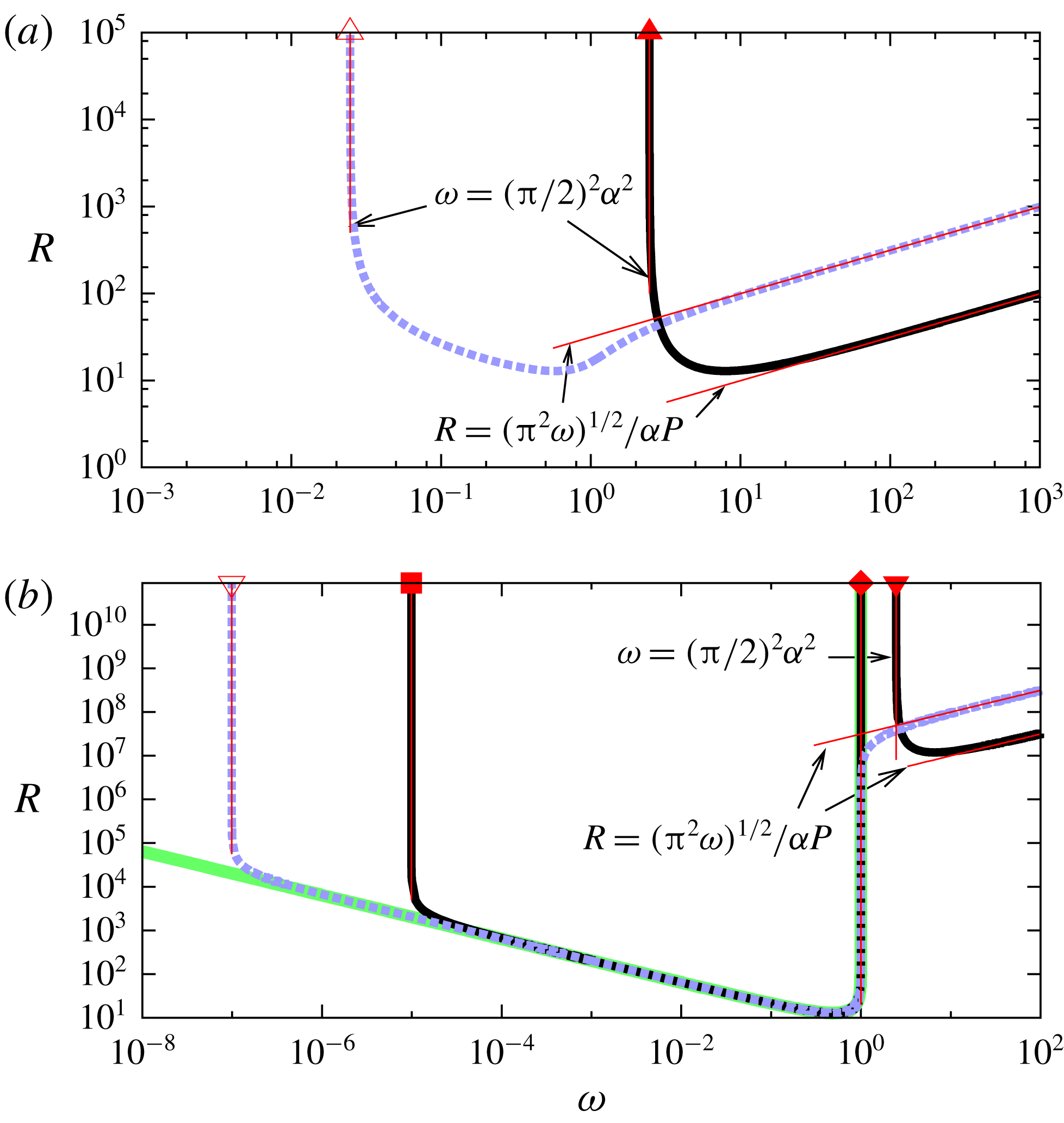
The neutral curves for the shearing box computation. The black solid and blue dashed curves are the results for
 $\unicode[STIX]{x1D6FC}=1$
and
 $\unicode[STIX]{x1D6FC}=0.1$
, respectively. (a)
 $P=1$
, (b)
 $P=10^{-6}$
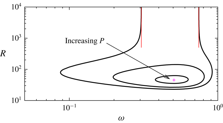
. The thin red lines are the asymptotic results; see (3.11) for the ideal limit, (5.6) for the high-rotation limit and figure 5 for the long wavelength limit. The thick green curve in (b) is the purely hydrodynamic result (3.12).

The easiest way to find the optimised neutral curve for a given
 $P$
,
 $\unicode[STIX]{x1D6FC}$
and
 $\unicode[STIX]{x1D714}$
is to solve equation (3.9) for
 $R^{2}$
, which must be minimised against the wavenumbers
 $k$
and
 $n$
. The neutral curves of the shearing box computations are summarised in figure 1. The stability diagram is point symmetric in the
 $\unicode[STIX]{x1D714}$
–
 $R$
plane, so hereafter we only consider positive
 $R$
. The flow is always stable when
 $\unicode[STIX]{x1D714}$
is negative so this region is not shown throughout the paper. At the narrow-gap limit the inequalities (1.1) and (1.2) become
 $\unicode[STIX]{x1D714}<0$
and
 $\unicode[STIX]{x1D714}(1-\unicode[STIX]{x1D714})<0$
, respectively. There are two Rayleigh stable regions; cyclonic (
 $\unicode[STIX]{x1D714}<0$
) and anticyclonic (
 $\unicode[STIX]{x1D714}>1$
) regimes, where the Kepler rotation
 $\unicode[STIX]{x1D714}=4/3$
(see (2.7), (3.1b
)) belongs to the latter.
For large to moderate magnetic Prandtl numbers the shape of the neutral curve is rather simple as can be seen in figure 1(a) where
 $P=1$
. There are two curves shown for
 $\unicode[STIX]{x1D6FC}=1$
(black solid curve) and
 $\unicode[STIX]{x1D6FC}=0.1$
(blue dashed curve). Above the neutral curves, the corresponding flow becomes linearly unstable. Decreasing
 $\unicode[STIX]{x1D6FC}$
, the left-hand branch is destabilised, while the right-hand branch is stabilised. Both branches appear to converge towards some large Reynolds number asymptotic states, which are our main interest here. The behaviour of the left-hand branch can be explained by the ideal result (the right-hand branch converges to the high-rotation limit to be derived in § 5). The optimised ideal mode at
 $(k,n)=(0,1)$
found by (3.8) gives the stability boundary
 $$\begin{eqnarray}\displaystyle \frac{\unicode[STIX]{x1D714}}{\unicode[STIX]{x1D6FC}^{2}}=\left(\frac{\unicode[STIX]{x03C0}}{2}\right)^{2}, & & \displaystyle\end{eqnarray}$$
which corresponds to the thin red vertical lines in the figure. The larger the normalised magnetic field
 $\unicode[STIX]{x1D6FC}$
is, the larger the critical value of
 $\unicode[STIX]{x1D714}$
should be. Thus, (3.11) describes the Velikhov’s stabilisation mechanism by the external magnetic field.
The ideal result (3.11) is independent of
 $P$
so one may expect to see similar agreement for small values of
 $P$
of experimental interest. However, we remarked upon earlier that at the vanishing magnetic Prandtl number limit the stability of the flow should become purely hydrodynamic. At first glance those two statements might look inconsistent, because on one hand the ideal limit predicts that there is no instability below the critical value of
 $\unicode[STIX]{x1D714}$
, which is large when the strong magnetic field is applied, but on the other hand hydrodynamic instability should occur for
 $\unicode[STIX]{x1D714}\in [0,1]$
.
The behaviour of the neutral curve for smaller magnetic Prandtl numbers can be found in figure 1(b). Here we set
 $P=10^{-6}$
to compute the stability. The solid curve for
 $\unicode[STIX]{x1D6FC}=1$
shows the typical neutral curve when the magnetic field is strong. There are actually two islands of instability, the right of which is an analogue to the result of the previous panel and indeed the ideal result predicts the behaviour of its left-hand branch. When the applied magnetic field is weaker and the ideal limit value of
 $\unicode[STIX]{x1D714}$
is smaller than unity the ideal limit is not observable; see the dashed curve for
 $\unicode[STIX]{x1D6FC}=0.1$
in figure 1(b), where the two islands of the instability merge. The neutral curve appearing at the Rayleigh unstable region might be explained by the hydrodynamic instability (3.10). In fact, for not too large
 $R$
, the curve can be approximated by the hydrodynamic result plotted by the thick green curve in figure 1(b). This curve can be found by optimising (3.10) as
 $$\begin{eqnarray}\displaystyle R^{2}\unicode[STIX]{x1D714}(1-\unicode[STIX]{x1D714})=T, & & \displaystyle\end{eqnarray}$$
where
 $T$
is the well-known critical Taylor number
 $27\unicode[STIX]{x03C0}^{4}/64\approx 41.094$
. The value of
 $T$
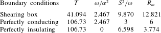
and some key numbers to be derived in the asymptotic analysis are summarised in table 1.
The key numbers in the asymptotic analysis for the narrow-gap cases.
 $T$
: the critical Taylor number for the hydrodynamic limit (3.12).
 $\unicode[STIX]{x1D714}/\unicode[STIX]{x1D6FC}^{2}$
: the critical value for the ideal limit (see (3.11) and § 3.3).
 $S^{2}/\unicode[STIX]{x1D714}$
: the critical value for the high-rotation limit (see (5.6), (5.17) and (5.19)).
 $R_{m}$
: the critical magnetic Reynolds number for the high-rotation limit for all possible external magnetic fields (see (5.10) and appendix B).

However, it is not clear how the neutral curve in the top panel deforms into that in the bottom panel at this stage. For large enough Reynolds numbers the hydrodynamic approximation of the instability fails and the neutral curve tends to some constant
 $\unicode[STIX]{x1D714}$
. We shall show in § 4 that the asymptotic analysis of this unknown large Reynolds number state yields the critical value of
 $P$
at which the instability of the Rayleigh unstable region abruptly appears. That new asymptotic limit occurs when we select small wavenumbers of
 $O(R^{-1})$
. We have seen that the optimum of the ideal limit also occurs at small
 $k$
, but we will see that it should still be larger than
 $O(R^{-1})$
in the asymptotic sense.
3.3 The perfectly conducting and insulating boundary conditions
For the other two magnetic boundary conditions (3.3) and (3.4) we must numerically solve differential equations (3.2). Before developing the narrow-gap code, the wide-gap equations (2.11) were numerically solved to check the results with Goodman & Ji (Reference Goodman and Ji2002), Willis & Barenghi (Reference Willis and Barenghi2002) and some axisymmetric results listed in Rüdiger et al. (Reference Rüdiger, Gellert, Hollerbach, Schultz and Stefani2018a
). The independent narrow-gap code is then tested against the wide-gap code with
 $\unicode[STIX]{x1D702}=0.999$
. The equations are discretised by substituting the modified Chebyshev expansions and evaluated at the collocation points; see appendix A. The resultant linear eigenvalue problem for the eigenvalue
 $\unicode[STIX]{x1D70E}$
can be solved by LAPACK routines.
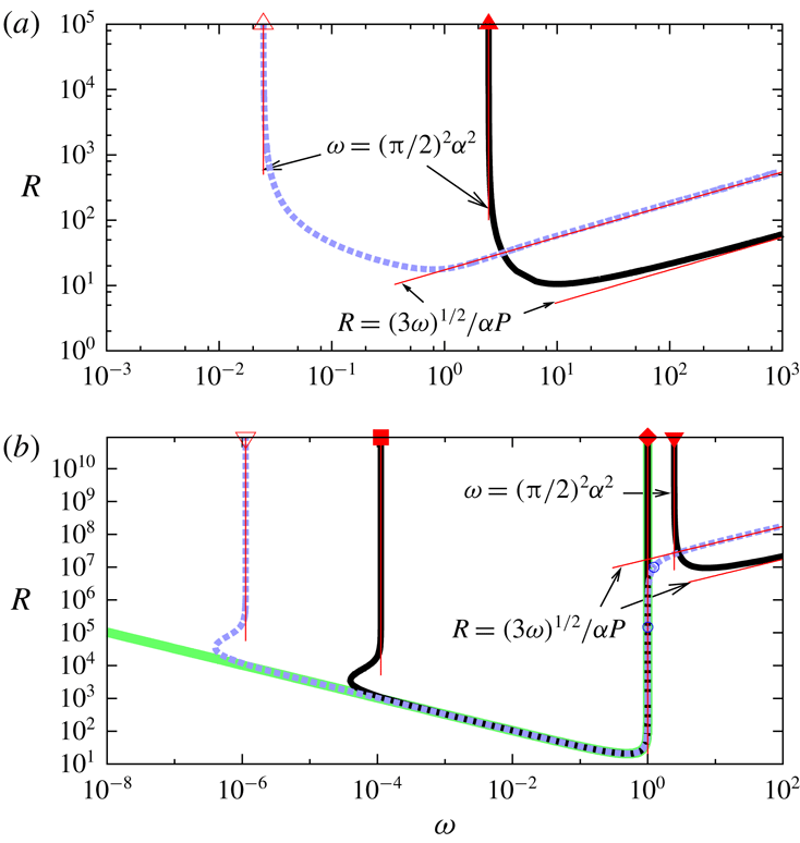
The same picture as figure 1 but for the perfectly conducting boundary conditions at the narrow-gap limit. The thin red lines are the asymptotic results; see (3.11) for the ideal limit, (5.17) for the high-rotation limit and figure 7 for the long wavelength limit. The blue circles correspond to the onset of the oscillatory mode.


As in the previous section we fix
 $\unicode[STIX]{x1D6FC}$
and
 $P$
as some constants and seek the neutral curve in the
 $\unicode[STIX]{x1D714}$
–
 $R$
plane. The largest real part of the eigenvalues must be maximised against
 $k$
to find the most dangerous mode. The zero locus of the optimised value can then be found by bisection to draw the neutral curve. The numerical resolutions are tested using up to 600 Chebyshev modes.
Figure 2 shows the neutral curve for the perfectly conducting walls. The first thing to note is that this figure is similar to figure 1, meaning that the ‘local approximation’ captures some qualitative aspects of the global stability result when the cylinders are perfectly conducting and the gap between them is narrow. In particular, the identical ideal limits can be seen, as shown in the upper panels. This is because the ideal solution (3.8) for the most dangerous mode
 $n=1$
also satisfies the perfectly conducting boundary conditions for
 $\unicode[STIX]{x1D713}$
shown in (3.3). (The other boundary conditions can be accounted by inserting thin passive near wall boundary layers similar to § 5.) The results shown in the lower panel for smaller
 $P$
again indicate the emergence of the instability in the Rayleigh unstable region. For not too large Reynolds numbers it can be approximated by the hydrodynamic result (3.12) but with
 $T\approx 106.73$
for no-slip boundaries (Taylor Reference Taylor1923).
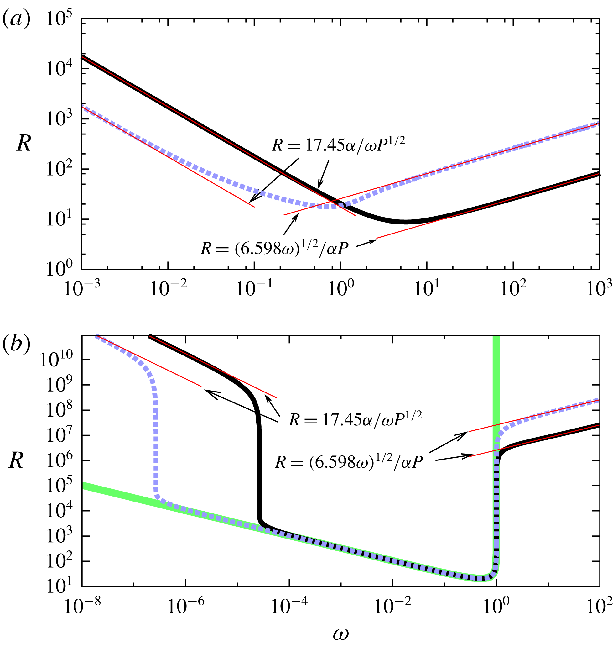
Figure 3 displays the results for the perfectly insulating condition where we find similar convergence to the hydrodynamic result for the small
 $P$
limit. However, for large
 $R$
, the asymptotic property of the neutral curve is qualitatively different from the previous two cases. The most striking feature of the upper panel is the apparent absence of the ideal limit of
 $\unicode[STIX]{x1D714}$
below which the flow is stabilised. The fact is that the threshold value for the perfectly insulating case is predicted to be zero, because the optimised solution of the reduced differential equation (3.6) with the conditions for
 $\unicode[STIX]{x1D713}$
shown in (3.4) is merely
 $\unicode[STIX]{x1D714}=k=0,n=1,\unicode[STIX]{x1D713}=1$
for any
 $\unicode[STIX]{x1D6FC}$
. Hence, the neutral curve should tend to
 $\unicode[STIX]{x1D714}=0$
for large enough Reynolds numbers. However, before reaching this limit the left hand branch of the neutral curve displays an unknown asymptotic trend where
 $R\unicode[STIX]{x1D714}$
seems to converge towards some constant. The detailed asymptotic analysis of this state will be studied in § 4.
3.4 The wide-gap cases
The ideal limit result for the perfectly conducting case can be extended to more general wide-gap Taylor–Couette flow. Neglecting all the diffusive terms from equations (2.11) we have
 $$\begin{eqnarray}\displaystyle \triangle \unicode[STIX]{x1D713}+\frac{4}{\unicode[STIX]{x1D6FD}^{2}r^{2}}\left(\frac{R_{s}}{R_{p}}+\frac{1}{r^{2}}\right)\unicode[STIX]{x1D713}=0, & & \displaystyle\end{eqnarray}$$
where
 $\unicode[STIX]{x1D6FD}=B_{0}/R_{p}$
is the inverse magnetic Mach number (note that this parameter is redefined from the narrow-gap case for the sake of simplicity). The most dangerous mode occurring at
 $k=0$
can be found using Bessel functions of fractional order
 $\pm \unicode[STIX]{x1D707}$
, where
 $$\begin{eqnarray}\displaystyle \unicode[STIX]{x1D707}=\sqrt{1-\frac{4R_{s}}{R_{p}\unicode[STIX]{x1D6FD}^{2}}}. & & \displaystyle\end{eqnarray}$$
The boundary conditions for
 $\unicode[STIX]{x1D713}$
, shown in (2.13), can be satisfied if the dispersion relation
 $$\begin{eqnarray}\displaystyle 0=f(R_{p}/R_{s},\unicode[STIX]{x1D6FD},\unicode[STIX]{x1D702})=\text{J}_{\unicode[STIX]{x1D707}}\left(\frac{2}{\unicode[STIX]{x1D6FD}r_{i}}\right)\text{J}_{-\unicode[STIX]{x1D707}}\left(\frac{2}{\unicode[STIX]{x1D6FD}r_{o}}\right)-\text{J}_{\unicode[STIX]{x1D707}}\left(\frac{2}{\unicode[STIX]{x1D6FD}r_{o}}\right)\text{J}_{-\unicode[STIX]{x1D707}}\left(\frac{2}{\unicode[STIX]{x1D6FD}r_{i}}\right) & & \displaystyle\end{eqnarray}$$
holds. Here
 $\text{J}_{\unicode[STIX]{x1D707}}$
is the Bessel function of
 $\unicode[STIX]{x1D707}$
th order. The behaviour of the critical value
 $R_{s}/R_{p}$
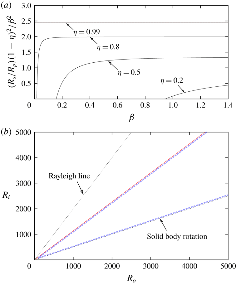
found by (3.15) is shown in figure 4(a). The rescaled variable
 $(R_{s}/R_{p})(1-\unicode[STIX]{x1D702})^{2}/\unicode[STIX]{x1D6FD}^{2}$
is used for the vertical coordinate because this quantity tends to
 $\unicode[STIX]{x1D714}/\unicode[STIX]{x1D6FC}^{2}$
at the narrow-gap limit. The convergence to the narrow-gap result (3.11), shown by the red dashed line, can indeed be found in the figure when
 $\unicode[STIX]{x1D702}$
approaches unity. For
 $\unicode[STIX]{x1D702}<1$
the rescaled variable in the figure does not become a constant, although it tends towards a constant for large
 $\unicode[STIX]{x1D6FD}$
.
(a) The ideal limit solutions for the perfectly conducting wide-gap cylinders. Equation (3.15) is used. The horizontal red dashed line is the narrow-gap result
 $\unicode[STIX]{x03C0}^{2}/4$
; see (3.11). (b) The comparison of the ideal result (thin red line) and the full neutral curve for
 $\unicode[STIX]{x1D702}=0.5,\unicode[STIX]{x1D6FD}=0.2,P=1$
. The latter result found by the viscous resistive MHD equations (2.11) predicts that the flow is unstable within the wedge shaped domain formed by the blue dashed curve.

Figure 4(b) compares the ideal result with the full stability for
 $\unicode[STIX]{x1D702}=0.5,\unicode[STIX]{x1D6FD}=0.2$
and
 $P=1$
. The result is plotted in the
 $R_{o}$
–
 $R_{i}$
plane; here the entire counter-rotation regime (
 $R_{o}R_{i}<0$
) and the region above the Rayleigh line
 $R_{s}=0$
(
 $R_{i}=\unicode[STIX]{x1D702}^{-1}R_{o}$
) is unstable in terms of (1.2). In addition to the Rayleigh unstable regime, the MRI could also occur in the anticyclonic regime, which is the wedge shaped region between the Rayleigh line and the solid-body rotation line
 $R_{p}=0$
(
 $R_{i}=\unicode[STIX]{x1D702}R_{o}$
). For the selected parameters, the neutral curve sits in this region as shown by the thick blue dashed curve. This curve was computed by solving differential equations (2.11) with the boundary conditions (2.13) by the Chebyshev collocation method.
The behaviour of the upper neutral curve can be captured by the ideal result shown by the thin red line. For given
 $\unicode[STIX]{x1D702}$
and
 $\unicode[STIX]{x1D6FD}$
the slope of the line can be found from the upper panel. From the trend of the asymptotic result, we find that for larger
 $\unicode[STIX]{x1D6FD}$
values the ideal line approaches the solid-body rotation line. Thus, as we have seen in figure 2(a), the ideal result describes the stabilisation effect by the applied magnetic field. (Likewise the lower neutral curve corresponds to the high-rotation limit to be shown in figure 5. When
 $\unicode[STIX]{x1D6FD}$
is fixed, this limit coincides with the solid-body rotation line.)
4 The long wavelength limits
When the wavelength is large (equivalently
 $k$
gets small) some diffusive terms are still retained even at the large Reynolds number limit. This is because the driving mechanisms brought about by the shear and the magnetic field are multiplied by
 $k$
as seen in (2.11); hence the underlying physics of the limit is somewhat similar to Prandtl’s boundary layer theory. Here, for the sake of simplicity, we focus only on the narrow-gap limit equations. Parameters
 $P$
and
 $\unicode[STIX]{x1D6FC}$
are
 $O(1)$
constants throughout this section.
4.1 The shearing box computations
We start the asymptotic analysis for the periodic boundary conditions. First we note that by writing
 $$\begin{eqnarray}\displaystyle K=\frac{P(kR\unicode[STIX]{x1D6FC})^{2}}{l^{4}},\quad \unicode[STIX]{x1D6FA}=\frac{\unicode[STIX]{x1D714}}{\unicode[STIX]{x1D6FC}^{2}},\quad {\mathcal{P}}=\frac{P}{1-\unicode[STIX]{x1D714}}, & & \displaystyle\end{eqnarray}$$
equation (3.9) can be simplified to
 $$\begin{eqnarray}\displaystyle (1+K)^{2}l^{2}=K\unicode[STIX]{x1D6FA}({\mathcal{P}}^{-1}+K). & & \displaystyle\end{eqnarray}$$
In the long wavelength limit we fix
 $(kR)$
as
 $O(R^{0})$
, while taking the limit of large
 $R$
. Equation (4.2) is unchanged, except that
 $l=n\unicode[STIX]{x03C0}/2$
becomes independent of
 $k$
.
The quantity
 $K$
can be regarded as the square of the scaled axial wavenumber. Thus, in order to find the approximation of the neutral curve we must optimise
 $\unicode[STIX]{x1D714}$
against
 $K$
for fixed
 $P$
and
 $\unicode[STIX]{x1D6FC}$
. Differentiating (4.2) by
 $K$
and requiring
 $\unicode[STIX]{x2202}\unicode[STIX]{x1D714}/\unicode[STIX]{x2202}K=0$
, we find that the extremum occurs at
 $$\begin{eqnarray}\displaystyle K=\frac{\displaystyle \frac{\unicode[STIX]{x1D6FA}}{2{\mathcal{P}}}-l^{2}}{l^{2}-\unicode[STIX]{x1D6FA}}. & & \displaystyle\end{eqnarray}$$
Eliminating
 $K$
from (4.2) and (4.3) gives
 $$\begin{eqnarray}\displaystyle \unicode[STIX]{x1D6FA}=4l^{2}{\mathcal{P}}(1-{\mathcal{P}}). & & \displaystyle\end{eqnarray}$$
Hence, substituting (4.4) into (4.3) gives
 $$\begin{eqnarray}\displaystyle K=\frac{1}{1-2{\mathcal{P}}}. & & \displaystyle\end{eqnarray}$$
The most dangerous perturbation arises for
 $n=1$
, so the neutral condition is simply
 $$\begin{eqnarray}\displaystyle \unicode[STIX]{x1D6FA}=\unicode[STIX]{x03C0}^{2}{\mathcal{P}}(1-{\mathcal{P}}) & & \displaystyle\end{eqnarray}$$
from (4.4). Figure 5(b) shows the asymptotic result for
 $\unicode[STIX]{x1D6FC}=0.1$
. Here we only plot the curve satisfying
 $1-2{\mathcal{P}}\geqslant 0$
, because it is the inverse of
 $K$
from (4.5) and hence must be positive by definition (4.1). Increasing
 $P$
from a very small value, the flow is eventually stabilised until the sharp corner of the neutral curve that appears for
 $P\in [0.1,1]$
. This corner is associated with the limit of
 ${\mathcal{P}}\rightarrow 1/2$
, where the value of
 $K$
tends to infinite. On the right of the corner we have a horizontal line corresponding to the ideal result (3.11). The neutral points about
 $P=10^{-6}$
(open reverse triangle) and
 $1$
(open triangle) were used for the asymptotic approximations for the blue thick dashed curves depicted in figure 1.
Figure 5(a) is a similar result, but for
 $\unicode[STIX]{x1D6FC}=1$
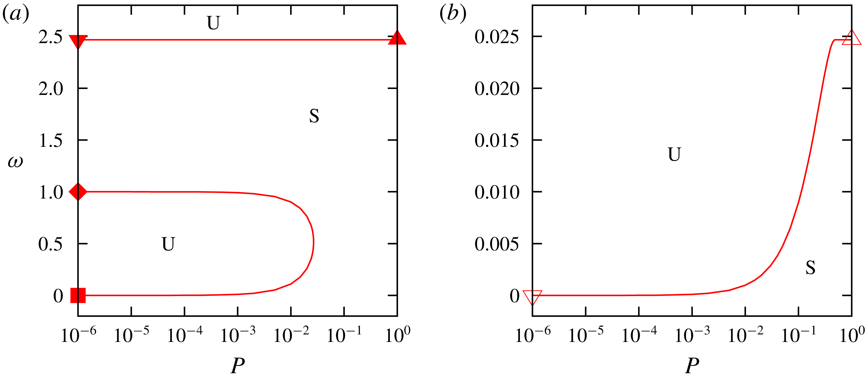
. Unlike the previous case there are two islands of instability, which are the counterparts of those seen in the full analysis. The horizontal line at the Rayleigh stable region is the ideal result, whilst the curve at the Rayleigh unstable region is the long wavelength limit result. The latter instability disappears at the critical value of
 $P\approx 0.02675$
, below which there are three neutral points. The three neutral points at
 $P=10^{-6}$
(filled square, diamond and reverse triangle) and the one neutral point at
 $P=1$
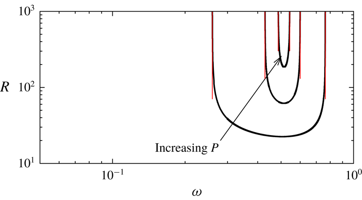
(filled triangle) are the asymptotic limits seen in figures 1(a) and 1(b), respectively. The behaviour of the full stability curve around the critical value of
 $P$
is illustrated in figure 6. The disappearance of the long wavelength limit exactly corresponds to the disappearance of the full instability in the Rayleigh unstable regime.
The neutral curve at the long wavelength limit for the shearing box case. The unstable region is labelled by ‘U’, the stable region is labelled by ‘S’. (a)
 $\unicode[STIX]{x1D6FC}=1$
, (b)
 $\unicode[STIX]{x1D6FC}=0.1$
.

The disappearance of the instability in the Rayleigh unstable regime with increasing
 $P$
. The shearing box is used for
 $\unicode[STIX]{x1D6FC}=1$
. The solid curves are the full neutral curves for
 $P=0.02,0.026,0.0267$
. The thin red lines are the corresponding long wavelength asymptotic limits; see figure 5(a).

4.2 The perfectly conducting conditions
A similar investigation is undertaken for the perfectly conducting cases. The long wavelength limit equations are found from (3.2) by taking the limit
 $R\rightarrow \infty$
, while fixing
 $kR$
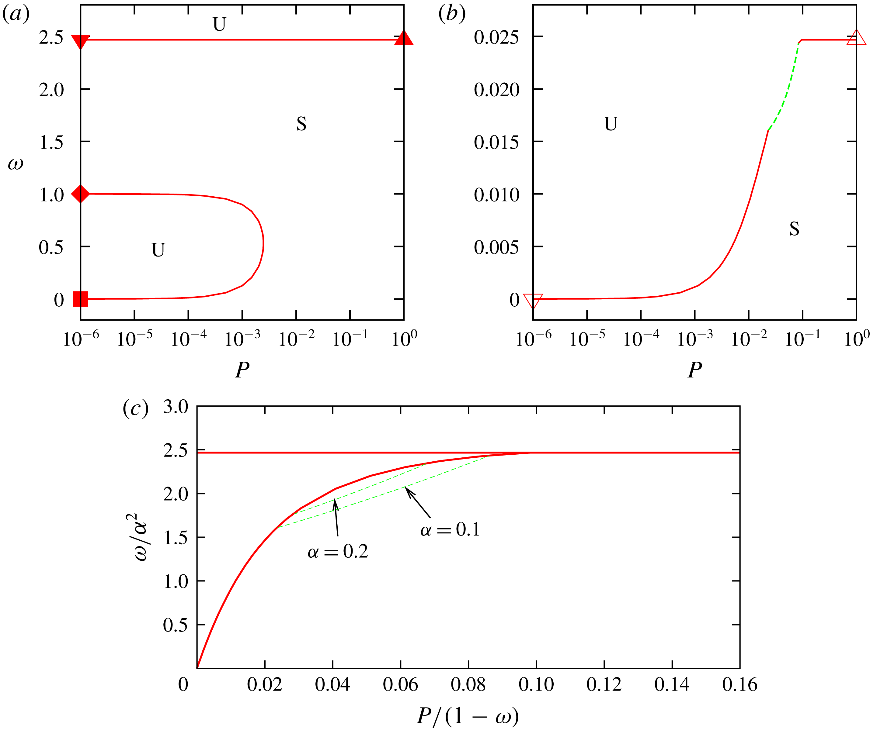
as a constant. This is the regular limit that ensures all of the boundary conditions (3.3). The computational results shown in figure 7(a,b) remain qualitatively similar to those in figure 5. As the previous figure for the shearing box case, the symbols on the curves represent the corresponding asymptotic results shown in figure 2.
Most of the neutral perturbations are steady, although oscillatory neutral modes are detected for some values of
 $\unicode[STIX]{x1D6FC}$
. This is indicated by the green dashed curve in figure 7(b). The behaviour of the steady modes are similar to the shearing box computation. Setting
 $\unicode[STIX]{x1D70E}=0$
, the long wavelength equations can be combined into the single equation
 $$\begin{eqnarray}\displaystyle \{\unicode[STIX]{x2202}_{y}^{4}+{(P^{1/2}\unicode[STIX]{x1D6FC}Rk)^{2}\}}^{2}\unicode[STIX]{x1D713}^{\prime \prime }+(P^{1/2}\unicode[STIX]{x1D6FC}Rk)^{2}\frac{\unicode[STIX]{x1D6FA}}{{\mathcal{P}}}\unicode[STIX]{x1D713}^{\prime \prime \prime \prime }+\unicode[STIX]{x1D6FA}(P^{1/2}\unicode[STIX]{x1D6FC}Rk)^{4}\unicode[STIX]{x1D713}=0. & & \displaystyle\end{eqnarray}$$
This equation suggests that the steady stability result obtained by optimising against the scaled wavenumber
 $(P^{1/2}\unicode[STIX]{x1D6FC}Rk)$
can be summarised by using
 $\unicode[STIX]{x1D6FA}$
and
 ${\mathcal{P}}$
defined in (4.1). Figure 7(c) displays the long wavelength results in terms of
 $\unicode[STIX]{x1D6FA}=\unicode[STIX]{x1D714}/\unicode[STIX]{x1D6FC}^{2}$
and
 ${\mathcal{P}}=P/(1-\unicode[STIX]{x1D714})$
. For any choice of
 $\unicode[STIX]{x1D6FC}$
, the steady modes are on the red curves in the figure (horizontal line is the ideal result appearing when
 $P^{1/2}\unicode[STIX]{x1D6FC}Rk\rightarrow \infty$
). The oscillatory mode only appears when
 $\unicode[STIX]{x1D6FC}\lesssim 0.2$
, as shown by the green dashed curve. The oscillatory mode can be found at finite Reynolds numbers. For example, for the thick blue dashed curve in figure 2 such a mode occurs around the Rayleigh line (more precisely, such mode appears between the two blue circles).
Another minor qualitative difference to the shearing box computation is that the instability in the Rayleigh unstable region exists beyond the critical value of
 $P$
found by the asymptotic analysis. Figure 8 shows the behaviour of the full neutral curve about the critical value
 $P\approx 0.00248$
for
 $\unicode[STIX]{x1D6FC}=1$
; figure 7(a). Unlike figure 6(c), there is a remnant of the instability enclosed by the neutral curve, but it reduces with increasing
 $P$
and vanishes at
 $P\approx 0.00641$
.
(a,b) The same results as figure 5 but for the perfectly conducting boundary conditions. The red solid/green dashed curves are the steady/oscillatory modes. (c) The results summarised in terms of
 $\unicode[STIX]{x1D714}/\unicode[STIX]{x1D6FC}^{2}$
and
 $P/(1-\unicode[STIX]{x1D714})$
. The red solid curve is the neutral steady modes for various
 $\unicode[STIX]{x1D6FC}$
. The green curves are the neutral oscillatory modes for
 $\unicode[STIX]{x1D6FC}=0.1$
and 0.2.

The same results as figure 6(c) but for the perfectly conducting boundary conditions. The solid curves are the full neutral curves for the
 $P=0.002,0.004,0.006$
, where equations (3.2) are solved for
 $\unicode[STIX]{x1D6FC}=1$
. The unstable region shrinks with increasing
 $P$
and disappear at the cross point when
 $P=0.00641$
. The red lines are the long wavelength asymptotic result for
 $P=0.002$
; see figure 7(a).

4.3 The perfectly insulating conditions
As we have seen in figure 3 the asymptotic behaviour of the left-hand branch of the perfectly insulating case is quite different from the other two boundary conditions. Nevertheless, the asymptotic limit can be explained by the long wavelength limit
 $kR\sim O(R^{0})$
, but with fixed
 $\unicode[STIX]{x1D714}R$
.
In order to find the limiting reduced system it is convenient to choose
 $k$
as a perturbation parameter rather than
 $R^{-1}$
. Let us define the rescaled
 $O(k^{0})$
parameters
 $\widetilde{k}=P^{1/2}\unicode[STIX]{x1D6FC}kR$
,
 $\widetilde{\unicode[STIX]{x1D714}}=P^{1/2}R\unicode[STIX]{x1D714}/\unicode[STIX]{x1D6FC}$
and expand
 $$\begin{eqnarray}\displaystyle & \displaystyle \unicode[STIX]{x1D713}=\unicode[STIX]{x1D713}_{0}+k\unicode[STIX]{x1D713}_{1}+\cdots \,,\quad P^{1/2}R\unicode[STIX]{x1D714}kv=v_{0}+kv_{1}+\cdots \,, & \displaystyle\end{eqnarray}$$
 $$\begin{eqnarray}\displaystyle & \displaystyle R\unicode[STIX]{x1D714}kb=b_{0}+kb_{1}+\cdots \,,\quad P^{1/2}\unicode[STIX]{x1D719}=\unicode[STIX]{x1D719}_{0}+k\unicode[STIX]{x1D719}_{1}+\cdots \,. & \displaystyle\end{eqnarray}$$
 $O(k^{0})$
we find
 $$\begin{eqnarray}\displaystyle & \displaystyle \unicode[STIX]{x1D719}_{0}^{\prime \prime \prime \prime }+\text{i}\widehat{k}\unicode[STIX]{x1D713}_{0}^{\prime \prime }+\text{i}v_{0}=0,\quad v_{0}^{\prime \prime }+\text{i}\widehat{k}b_{0}=0, & \displaystyle\end{eqnarray}$$
 $$\begin{eqnarray}\displaystyle & \displaystyle \unicode[STIX]{x1D713}_{0}^{\prime \prime }+\text{i}\widehat{k}\unicode[STIX]{x1D719}_{0}=0,\quad b_{0}^{\prime \prime }+\text{i}\widehat{k}v_{0}=0. & \displaystyle\end{eqnarray}$$
 $\unicode[STIX]{x1D713}_{0}^{\prime }=\unicode[STIX]{x1D719}_{0}=0$
must be satisfied at
 $x=\pm 1$
. This problem is exactly what we saw in the ideal limit at the optimum value
 $\unicode[STIX]{x1D714}=0$
. Within the asymptotic framework we interpret this as the vanishing leading-order terms of
 $O(R^{0})$
in the asymptotic expansion of
 $\unicode[STIX]{x1D714}$
. Therefore, we must examine the higher-order term in the expansion, namely
 $\widetilde{\unicode[STIX]{x1D714}}$
, to determine the stability.
In order to fix the value of
 $\widetilde{\unicode[STIX]{x1D714}}$
we must find the next-order equations at
 $O(k)$
. Using the leading-order solutions
 $\unicode[STIX]{x1D713}_{0}=1,\unicode[STIX]{x1D719}_{0}=0$
we have
 $$\begin{eqnarray}\displaystyle & \displaystyle \unicode[STIX]{x1D719}_{1}^{\prime \prime \prime \prime }+\text{i}\widetilde{k}\unicode[STIX]{x1D713}_{1}^{\prime \prime }+\text{i}v_{1}=0,\quad v_{1}^{\prime \prime }+\text{i}\widetilde{k}b_{1}=0, & \displaystyle\end{eqnarray}$$
 $$\begin{eqnarray}\displaystyle & \displaystyle \unicode[STIX]{x1D713}_{1}^{\prime \prime }+\text{i}\widetilde{k}\unicode[STIX]{x1D719}_{1}=0,\quad b_{1}^{\prime \prime }+\text{i}\widetilde{k}v_{1}=\text{i}\widetilde{k}\widetilde{\unicode[STIX]{x1D714}}, & \displaystyle\end{eqnarray}$$
 $$\begin{eqnarray}\displaystyle v_{1}=\unicode[STIX]{x1D719}_{1}=\unicode[STIX]{x1D719}_{1}^{\prime }=b_{1}=0,\quad \unicode[STIX]{x1D713}_{1}^{\prime }\pm 1=0\quad \text{at }x=\pm 1. & & \displaystyle\end{eqnarray}$$
This is the inhomogeneous form of the leading-order equations and the solvability condition gives the dispersion relation.
The easiest way to find that condition would be is to combine the equations in (4.10) to
 $$\begin{eqnarray}\displaystyle \frac{\unicode[STIX]{x1D6F9}^{(8)}}{\widetilde{k}^{4}}+2\frac{\unicode[STIX]{x1D6F9}^{(4)}}{\widetilde{k}^{2}}+\unicode[STIX]{x1D6F9}=0, & & \displaystyle\end{eqnarray}$$
where
 $\unicode[STIX]{x1D6F9}=\unicode[STIX]{x1D713}_{1}^{\prime \prime }+\widetilde{\unicode[STIX]{x1D714}}/\widetilde{k}$
. Assuming
 $\unicode[STIX]{x1D6F9}$
is an even function, the general solution of (4.12) can be found as
 $\unicode[STIX]{x1D6F9}=A_{1}S_{S}+A_{2}C_{C}+A_{3}\unicode[STIX]{x1D705}xS_{C}+A_{4}\unicode[STIX]{x1D705}xC_{S}$
, where
 $$\begin{eqnarray}\displaystyle S_{S}=\sin (\unicode[STIX]{x1D705}x)\sinh (\unicode[STIX]{x1D705}x),\quad C_{C}=\cos (\unicode[STIX]{x1D705}x)\cosh (\unicode[STIX]{x1D705}x), & & \displaystyle\end{eqnarray}$$
 $$\begin{eqnarray}\displaystyle S_{C}=\sin (\unicode[STIX]{x1D705}x)\cosh (\unicode[STIX]{x1D705}x),\quad C_{S}=\cos (\unicode[STIX]{x1D705}x)\sinh (\unicode[STIX]{x1D705}x), & & \displaystyle\end{eqnarray}$$
and
 $\unicode[STIX]{x1D705}=(\widetilde{k}/2)^{1/2}$
. The five unknown constants
 $A_{1},A_{2},A_{3},A_{4}$
and
 $\widetilde{\unicode[STIX]{x1D714}}$
can be fixed by applying the following five conditions found from (4.10) and (4.11):
 $$\begin{eqnarray}\displaystyle \unicode[STIX]{x1D6F9}^{(4)}=\unicode[STIX]{x1D6F9}^{(1)}=\unicode[STIX]{x1D6F9}^{(6)}+\widetilde{k}^{2}\unicode[STIX]{x1D6F9}^{(2)}=0,\quad \unicode[STIX]{x1D6F9}=\frac{\widetilde{\unicode[STIX]{x1D714}}}{\widetilde{k}},\quad \text{at }x=1 & & \displaystyle\end{eqnarray}$$
and
 $$\begin{eqnarray}\displaystyle \int _{0}^{1}\unicode[STIX]{x1D6F9}\,\text{d}x=-1+\frac{\widetilde{\unicode[STIX]{x1D714}}}{\widetilde{k}}. & & \displaystyle\end{eqnarray}$$
After some algebra the dispersion relation can be found as
 $$\begin{eqnarray}\displaystyle \widetilde{\unicode[STIX]{x1D714}}(\widetilde{k})=\frac{\widetilde{k}\unicode[STIX]{x1D705}\unicode[STIX]{x1D6FE}_{3}}{(\unicode[STIX]{x1D705}\unicode[STIX]{x1D6FE}_{1}+\unicode[STIX]{x1D706}_{1})g_{1}+(\unicode[STIX]{x1D705}\unicode[STIX]{x1D6FE}_{2}+\unicode[STIX]{x1D706}_{2})g_{2}+(\unicode[STIX]{x1D705}\unicode[STIX]{x1D6FE}_{3}+\unicode[STIX]{x1D706}_{3})}, & & \displaystyle\end{eqnarray}$$
where
 $$\begin{eqnarray}\displaystyle & \displaystyle \unicode[STIX]{x1D6FE}_{1}=\{S_{C}(C_{S}^{2}+S_{C}^{2}-S_{S}^{2}+C_{C}^{2})-2C_{S}S_{S}C_{C}\}, & \displaystyle\end{eqnarray}$$
 $$\begin{eqnarray}\displaystyle & \displaystyle \unicode[STIX]{x1D706}_{1}=\{(C_{C}-S_{S})(S_{C}^{2}-C_{S}^{2})/2-(S_{S}+C_{C})C_{S}S_{C}\}, & \displaystyle\end{eqnarray}$$
 $$\begin{eqnarray}\displaystyle & \displaystyle \unicode[STIX]{x1D6FE}_{2}=\{C_{S}(C_{S}^{2}+S_{C}^{2}+S_{S}^{2}-C_{C}^{2})-2S_{C}S_{S}C_{C}\}, & \displaystyle\end{eqnarray}$$
 $$\begin{eqnarray}\displaystyle & \displaystyle \unicode[STIX]{x1D706}_{2}=\{(C_{C}+S_{S})(S_{C}^{2}-C_{S}^{2})/2-(S_{S}-C_{C})C_{S}S_{C}\}, & \displaystyle\end{eqnarray}$$
 $$\begin{eqnarray}\displaystyle & \displaystyle \unicode[STIX]{x1D6FE}_{3}=\{S_{S}(S_{C}-C_{S})+C_{C}(S_{C}+C_{S})\},\quad \unicode[STIX]{x1D706}_{3}=-(C_{S}^{2}+S_{C}^{2}), & \displaystyle\end{eqnarray}$$
 $$\begin{eqnarray}\displaystyle & \displaystyle g_{1}=-\frac{S_{S}-C_{C}}{4(S_{S}^{2}+C_{C}^{2})},\quad g_{2}=-\frac{S_{S}+C_{C}}{4(S_{S}^{2}+C_{C}^{2})} & \displaystyle\end{eqnarray}$$
 $x=1$
.
The minimum for
 $\widetilde{\unicode[STIX]{x1D714}}(\widetilde{k})$
can be found from (4.17) as
 $17.45$
at
 $\widetilde{k}=7.006$
. This leads to the asymptotic result
 $$\begin{eqnarray}\displaystyle R=\frac{17.45\unicode[STIX]{x1D6FC}}{\unicode[STIX]{x1D714}P^{1/2}}. & & \displaystyle\end{eqnarray}$$
The asymptotic lines in figure 3 capture the large Reynolds number behaviour of the full neutral curve.
5 The high-rotation limits
5.1 The shearing box computations
In order to find the large
 $\unicode[STIX]{x1D714}$
asymptotic limits observed in figures 1–3, it is convenient to use the normalised form similar to (2.16). We shall see that the limiting neutral curve is governed by the non-dimensional parameter
 $$\begin{eqnarray}\displaystyle C=\frac{S^{2}}{\unicode[STIX]{x1D714}}, & & \displaystyle\end{eqnarray}$$
which is the Rossby number multiplied by the square of the Lundquist number
 $S=R\unicode[STIX]{x1D6FC}P$
.
The narrow-gap analogue of (2.16) can be found by substituting
 $V=\unicode[STIX]{x1D6FC}v$
,
 $\unicode[STIX]{x1D6F7}=PR\unicode[STIX]{x1D6FC}\unicode[STIX]{x1D719},B=P^{-1}R^{-1}b$
into (3.2).
 $$\begin{eqnarray}\displaystyle & \displaystyle \frac{\triangle ^{2}\unicode[STIX]{x1D6F7}}{R^{4}P^{3}\unicode[STIX]{x1D6FC}^{2}}+\text{i}k\frac{\triangle \unicode[STIX]{x1D713}}{R^{2}P^{2}}+\text{i}k\frac{V}{C}=0, & \displaystyle\end{eqnarray}$$
 $$\begin{eqnarray}\displaystyle & \displaystyle \frac{\triangle V}{R^{2}P\unicode[STIX]{x1D6FC}^{2}}+\text{i}kB-\text{i}k\left(\frac{1}{C}-\frac{1}{R^{2}P^{2}\unicode[STIX]{x1D6FC}^{2}}\right)\unicode[STIX]{x1D6F7}=0, & \displaystyle\end{eqnarray}$$
 $$\begin{eqnarray}\displaystyle & \displaystyle \triangle \unicode[STIX]{x1D713}+\text{i}k\unicode[STIX]{x1D6F7}=0, & \displaystyle\end{eqnarray}$$
 $$\begin{eqnarray}\displaystyle & \displaystyle \triangle B+\text{i}kV-\text{i}k\unicode[STIX]{x1D713}=0. & \displaystyle\end{eqnarray}$$
 $R$
limit of this system is obtained by fixing the rescaled variables and
 $k$
,
 $\unicode[STIX]{x1D6FC}$
,
 $P$
,
 $C$
as
 $O(R^{0})$
quantities. From these assumptions and equation (5.1) we see that
 $\unicode[STIX]{x1D714}$
is indeed asymptotically large.
From (5.2a ) and (5.2b ) the hydrodynamic part of the leading order solution is simply
 $$\begin{eqnarray}\displaystyle V=0,\quad \unicode[STIX]{x1D6F7}=CB. & & \displaystyle\end{eqnarray}$$
Then for the other two equations we have the eigenvalue problem for
 $C$
 $$\begin{eqnarray}\displaystyle \triangle ^{2}\unicode[STIX]{x1D713}-Ck^{2}\unicode[STIX]{x1D713}=0. & & \displaystyle\end{eqnarray}$$
As we have seen in the previous sections the sinusoidal function of wavelength
 $4/n,n\in \mathbb{N}$
can be used to derive the dispersion relation
 $$\begin{eqnarray}\displaystyle C(k,n)=\frac{((n\unicode[STIX]{x03C0}/2)^{2}+k^{2})^{2}}{k^{2}}. & & \displaystyle\end{eqnarray}$$
The minimum
 $C=\unicode[STIX]{x03C0}^{2}\approx 9.870$
found at
 $k=\unicode[STIX]{x03C0}/2$
and
 $n=1$
gives the high-rotation limit of the neutral curve
 $$\begin{eqnarray}\displaystyle R=\frac{\sqrt{\unicode[STIX]{x03C0}^{2}\unicode[STIX]{x1D714}}}{\unicode[STIX]{x1D6FC}P}, & & \displaystyle\end{eqnarray}$$
which agrees with the asymptotic prediction in figure 1.
The high-rotation limit line (5.6) describes the transition from the hydrodynamic instability to the MRI in the anticyclonic regime. The key parameter is the Lundquist number as pointed out in Kirillov & Stefani (Reference Kirillov and Stefani2011) who used certain special property of the algebraic equation (3.9) rather than the asymptotic approach. From figure 1 we can see that for a given
 $\unicode[STIX]{x1D714}$
:
(i) If
 $R\ll O(1/\unicode[STIX]{x1D6FC}P)$
, namely the Lundquist number is small, then the flows satisfying Rayleigh’s condition (1.2) are stable.
(ii) If
$R\gg O(1/\unicode[STIX]{x1D6FC}P)$
, namely the Lundquist number is large, then the flows satisfying the Velikhov–Chandrasekhar condition (1.1) are stable.


We remarked earlier that the stability must approach the purely hydrodynamic case when either
 $P$
or
 $\unicode[STIX]{x1D6FC}$
approaches small values. The Velikhov–Chandrasekhar paradox occurs because in this argument we have implicitly assumed that
 $R$
is
 $O(1)$
, while taking the limit. For large enough
 $R$
, the limiting result (5.6) suggests that the MRI must appear in the Rayleigh stable region no matter how small
 $P$
and
 $\unicode[STIX]{x1D6FC}$
are, as long as they are finite. This conclusion is the same as Kirillov & Stefani (Reference Kirillov and Stefani2011), but what is remarkable here is that our asymptotic approach can be extended to more general cases, as we shall see in the subsequent discussions.
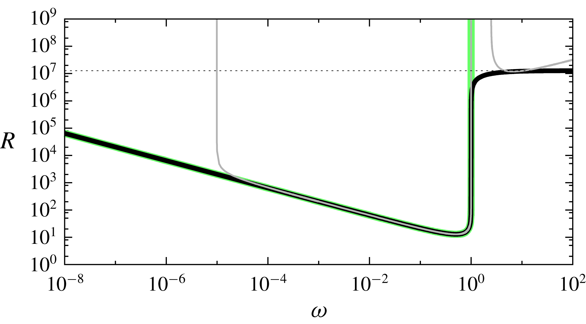
The thick black curve is the envelope of the neutral curves for various
 $\unicode[STIX]{x1D6FC}$
. The periodic boundary conditions are used and
 $P=10^{-6}$
. The thin grey curve is the neutral curve for
 $\unicode[STIX]{x1D6FC}=1$
, taken from figure 1. The thick green curve is the purely hydrodynamic result (
 $\unicode[STIX]{x1D6FC}=0$
). The horizontal dotted line is the high-rotation asymptotic result for the MRI (5.10).

For small
 $P$
the magnetic Reynolds number
 $R_{m}=PR$
becomes important (Goodman & Ji Reference Goodman and Ji2002). Actually the high-rotation asymptotic approximation is valid only when
 $R_{m}$
is sufficiently large. Consider the critical value of
 $R_{m}$
above which we can find an appropriate size of the magnetic field to switch on the MRI; this is equivalent to draw the envelope of the neutral curve for various values of
 $\unicode[STIX]{x1D6FC}$
. The black solid curve in figure 9 shows the envelope for
 $P=10^{-6}$
. For this particular magnetic Prandtl number clear separation of the hydrodynamic instability and the MRI is observed, where the latter only occurs when
 $R_{m}$
is large. Any neutral curve with fixed
 $\unicode[STIX]{x1D6FC}$
should sit above this envelope; see the thin grey curve computed for
 $\unicode[STIX]{x1D6FC}=1$
.
We can approximate the critical value of
 $R_{m}$
from the high-rotation limit of the envelope. Let us rewrite (3.2) using
 $V=\unicode[STIX]{x1D6FC}v$
,
 $\unicode[STIX]{x1D711}=\unicode[STIX]{x1D6FC}\unicode[STIX]{x1D719}$
,
 $R_{m}=PR$
,
 $A=\unicode[STIX]{x1D6FC}^{2}/\unicode[STIX]{x1D714}$
to have the rescaled system
 $$\begin{eqnarray}\displaystyle & \displaystyle \unicode[STIX]{x1D714}^{-1}A^{-1}\triangle ^{2}\unicode[STIX]{x1D711}+\text{i}kR(\triangle \unicode[STIX]{x1D713}+A^{-1}V)=0, & \displaystyle\end{eqnarray}$$
 $$\begin{eqnarray}\displaystyle & \displaystyle \unicode[STIX]{x1D714}^{-1}A^{-1}\triangle V+\text{i}kR(b-(1-\unicode[STIX]{x1D714}^{-1})A^{-1}\unicode[STIX]{x1D711})=0, & \displaystyle\end{eqnarray}$$
 $$\begin{eqnarray}\displaystyle & \displaystyle \triangle \unicode[STIX]{x1D713}+\text{i}kR_{m}\unicode[STIX]{x1D711}=0, & \displaystyle\end{eqnarray}$$
 $$\begin{eqnarray}\displaystyle & \displaystyle \triangle b+\text{i}kR_{m}V-\text{i}kR_{m}\unicode[STIX]{x1D713}=0. & \displaystyle\end{eqnarray}$$
 $\unicode[STIX]{x1D714}$
limit where
 $k,V,\unicode[STIX]{x1D719},b,\unicode[STIX]{x1D713},R_{m},A$
are assumed to be
 $O(\unicode[STIX]{x1D714}^{0})$
, then equations (5.7) can be reduced to
 $$\begin{eqnarray}\displaystyle \triangle ^{2}\unicode[STIX]{x1D713}-k^{2}R_{m}^{2}A(A\triangle \unicode[STIX]{x1D713}+\unicode[STIX]{x1D713})=0. & & \displaystyle\end{eqnarray}$$
The use of the sinusoidal function then yields the dispersion relation
 $$\begin{eqnarray}\displaystyle R_{m}^{2}=\frac{l^{4}}{k^{2}(A-l^{2}A^{2})}. & & \displaystyle\end{eqnarray}$$
The right-hand side is then minimised against the wavenumbers
 $k,n$
and the normalised magnetic field
 $A$
to find the approximation of the envelope. The optimised value
 $$\begin{eqnarray}\displaystyle R_{m}=\sqrt{27}\frac{\unicode[STIX]{x03C0}^{2}}{4}\approx 12.821 & & \displaystyle\end{eqnarray}$$
at
 $k=\unicode[STIX]{x03C0}/2\sqrt{2}\approx 1.111$
,
 $n=1$
,
 $A=1/2l^{2}\approx 0.1351$
is the horizontal dotted line in figure 9. If
 $R_{m}$
is larger than this critical value, (5.6) can be used to approximate the asymptotic behaviour of the MRI.
5.2 The narrow-gap limit results
Now let us include the effect of the walls. Since the viscous terms are removed in the high-rotation limit we must consider near wall boundary layers to satisfy the boundary conditions for the hydrodynamic parts. The asymptotic structure is similar to the small
 $P$
analysis given by Goodman & Ji (Reference Goodman and Ji2002), but we are concerned with the different asymptotic regimes.
First we consider the case for perfectly conducting walls. The limiting neutral condition can again be found by (5.4) but now we must apply the boundary conditions
 $$\begin{eqnarray}\displaystyle \unicode[STIX]{x1D713}=\unicode[STIX]{x1D713}^{\prime \prime \prime }-k^{2}\unicode[STIX]{x1D713}^{\prime }=0\quad \text{at }x=\pm 1 & & \displaystyle\end{eqnarray}$$
that ensures the magnetic boundary conditions
 $\unicode[STIX]{x1D713}=B^{\prime }=0$
are satisfied on the walls. The boundary conditions for the hydrodynamic parts are taken care of by the near-wall boundary layer of thickness
 $O(R^{-1})$
. The boundary layer equations near
 $x=\pm 1$
can be obtained by considering
 $\unicode[STIX]{x1D6F7},V,\unicode[STIX]{x1D713},B$
as a function of the stretched variable
 $X=(x\mp 1)/R$
in (5.2). Within the boundary layer
 $\unicode[STIX]{x1D713}$
and
 $B$
can be written by a local Taylor expansion of the outer solutions, and hence they are merely a linear function and a constant, respectively. Solutions
 $V$
and
 $\unicode[STIX]{x1D6F7}$
can be found by the rescaled hydrodynamic equations
 $$\begin{eqnarray}\displaystyle & \displaystyle \frac{\unicode[STIX]{x1D6F7}_{XXXX}}{P^{3}\unicode[STIX]{x1D6FC}^{2}}+\text{i}kC^{-1}V=0, & \displaystyle\end{eqnarray}$$
 $$\begin{eqnarray}\displaystyle & \displaystyle \frac{V_{XX}}{P\unicode[STIX]{x1D6FC}^{2}}+\text{i}kB-\text{i}kC^{-1}\unicode[STIX]{x1D6F7}=0, & \displaystyle\end{eqnarray}$$
where
 $V\rightarrow 0,\unicode[STIX]{x1D6F7}\rightarrow CB$
as
 $|X|\rightarrow \infty$
. There are three decaying and three growing roots in the characteristic equation, so the inner solution that matches to the outer solution can satisfy all the required boundary conditions on the walls. Clearly the boundary layer is passive, in the sense that it does not affect the outer eigenvalue problem.
The minimum for
 $C$
occurs as
 $k\rightarrow 0$
, and that limiting value can be found by substituting the expansion
 $$\begin{eqnarray}\displaystyle \unicode[STIX]{x1D713}=\unicode[STIX]{x1D713}_{0}+k^{2}\unicode[STIX]{x1D713}_{1}+\cdots & & \displaystyle\end{eqnarray}$$
into the outer equation (5.4). The leading-order problem is given as
 $$\begin{eqnarray}\displaystyle \unicode[STIX]{x1D713}_{0}^{\prime \prime \prime \prime }=0 & & \displaystyle\end{eqnarray}$$
with the boundary conditions
 $\unicode[STIX]{x1D713}_{0}=\unicode[STIX]{x1D713}_{0}^{\prime \prime \prime }=0$
at
 $x=\pm 1$
. Using the solution
 $\unicode[STIX]{x1D713}_{0}=1-x^{2}$
to the next-order problem, we have the inhomogeneous problem
 $$\begin{eqnarray}\displaystyle \unicode[STIX]{x1D713}_{1}^{\prime \prime \prime \prime }-2\unicode[STIX]{x1D713}_{0}^{\prime \prime }-C\unicode[STIX]{x1D713}_{0}=0 & & \displaystyle\end{eqnarray}$$
subject to
 $\unicode[STIX]{x1D713}_{1}=\unicode[STIX]{x1D713}_{1}^{\prime \prime \prime }-\unicode[STIX]{x1D713}_{0}^{\prime }=0$
at
 $x=\pm 1$
. Integrating (5.16) once gives
 $C=3$
. Therefore, the high-rotation limit for the perfectly conducting boundary conditions can be found as
 $$\begin{eqnarray}\displaystyle R=\frac{\sqrt{3\unicode[STIX]{x1D714}}}{\unicode[STIX]{x1D6FC}P}. & & \displaystyle\end{eqnarray}$$
For the perfectly insulating case we must solve (5.4) together with the magnetic boundary conditions
 $\unicode[STIX]{x1D713}^{\prime }\pm k\unicode[STIX]{x1D713}=0$
and
 $\unicode[STIX]{x1D713}^{\prime \prime }-k^{2}\unicode[STIX]{x1D713}=0$
(The hydrodynamic conditions are again satisfied through the boundary layer solutions that are similar to the perfectly conducting case). The general solutions are exponential functions and the boundary conditions are satisfied if the dispersion relation
 $$\begin{eqnarray}\displaystyle f(C,k)=l_{+}(\tanh l_{+})-l_{-}(\tan l_{-})+2k=0,\quad l_{\pm }=\sqrt{k\sqrt{C}\pm k^{2}} & & \displaystyle\end{eqnarray}$$
holds. A little numerical work yields the minimum value
 $C=6.598$
at
 $k=1.029$
. Thus, the high-rotation limit for the perfectly insulating boundary walls is
 $$\begin{eqnarray}\displaystyle R=\frac{\sqrt{6.598\unicode[STIX]{x1D714}}}{\unicode[STIX]{x1D6FC}P}. & & \displaystyle\end{eqnarray}$$
Both (5.17) and (5.19) predict the behaviour of the full numerical neutral curves shown in figures 2 and 3, respectively. Similar to the shearing box case, those approximations are valid when
 $R_{m}$
is sufficiently large. The critical values of
 $R_{m}$
, similar to (5.10), can be derived for the wall bounded cases as derived in appendix B and summarised in table 1.
5.3 Wide-gap cases
Finally, we extend the above high-rotation limits to the wide-gap cases. Here we fix
 $B_{0}$
rather than the magnetic Mach number; in fact most of the previous numerical computations concerned constant magnetic field cases. This does not cause any major change of the asymptotic structure discussed earlier. Thus, the outer region equations can be found by taking
 $R_{p}\rightarrow \infty$
in the rescaled system (2.16).
(a) The solution of the asymptotic problem (5.20). (b) The neutral curves for
 $\unicode[STIX]{x1D702}=0.5$
,
 $B_{0}=2$
,
 $P=1$
. There are two thick blue dashed neutral curves found by applying two boundary conditions (2.13), (2.14) for the full viscous resistive MHD equations (2.11). Above those curves the corresponding flows are unstable. The two red solid lines are the asymptotic results (5.21) with the values of
 $C$
taken from (a).

From the hydrodynamic part of the equations, (2.16a
), (2.16b
), we find simple solutions
 $V=0$
and
 $B=2\unicode[STIX]{x1D6F7}/Cr_{o}^{2}$
. Substituting those solutions into (2.16c
), (2.16d
) we have the eigenvalue problem
 $$\begin{eqnarray}\displaystyle \triangle ^{2}\unicode[STIX]{x1D713}-Ck^{2}\frac{r_{o}^{2}}{r^{2}}\unicode[STIX]{x1D713}=0, & & \displaystyle\end{eqnarray}$$
which must be solved subject to the magnetic part of the boundary conditions, namely (2.13) or (2.14), and replacing
 $b$
by
 $\triangle \unicode[STIX]{x1D713}$
. Again thin near-wall boundary layers must be inserted to satisfy the hydrodynamic part of the boundary conditions, but we omit further analysis as they are passive. Given
 $\unicode[STIX]{x1D702}$
we numerically find the minimum value of the eigenvalue
 $C$
against
 $k$
; the results are summarised in figure 10(a).
From the definitions of
 $C$
,
 $R_{p}$
and
 $R_{s}$
(see (2.15), (2.6)), we arrive at the conclusion that the neutral curve in the
 $R_{i}$
–
 $R_{o}$
plane asymptotes towards the straight line
 $$\begin{eqnarray}\displaystyle R_{i}=\frac{C+S^{2}\unicode[STIX]{x1D702}^{2}}{\unicode[STIX]{x1D702}(C+S^{2})}R_{o} & & \displaystyle\end{eqnarray}$$
which sits between the Rayleigh line and the solid-body rotation line. Figure 10(b) compares the asymptotic and full numerical results, and we find excellent agreements for both of the boundary conditions. (Similar to the previous cases, when
 $P$
is small such agreement could be found only when the magnetic Reynolds number is sufficiently grater than the critical value; see appendix B.) The slope of the asymptotic line is controlled only by the scaled Lundquist number
 $C^{-1/2}S$
. Increasing the Lundquist number, the anticyclonic region is eventually destabilised. In particular, we have the following limiting behaviours for the slope of the asymptotic line;
 $$\begin{eqnarray}\displaystyle & \displaystyle R_{i}/R_{o}\rightarrow \unicode[STIX]{x1D702}^{-1}\quad \text{(The Rayleigh line) as }C^{-1/2}S\rightarrow 0, & \displaystyle\end{eqnarray}$$
 $$\begin{eqnarray}\displaystyle & \displaystyle R_{i}/R_{o}\rightarrow \unicode[STIX]{x1D702}\quad \text{(The solid-body rotation line) as }C^{-1/2}S\rightarrow \infty , & \displaystyle\end{eqnarray}$$
 $C$
carries information of the boundary conditions to the asymptotic stability result. From figure 10(a) the conducting case is always more unstable than the insulating case. For a more general base flow, (5.20) becomes
 $$\begin{eqnarray}\displaystyle \triangle \left\{\frac{(rV_{b})^{\prime }}{r}\triangle \unicode[STIX]{x1D713}\right\}+S^{2}k^{2}r\left(\frac{V_{b}}{r}\right)^{\prime }\unicode[STIX]{x1D713}=0 & & \displaystyle\end{eqnarray}$$
from which we can derive the same conclusion in view of (1.1)–(1.2).
6 Conclusion
The large Reynolds number asymptotic approximations of the neutral curve are found for magnetised Taylor–Couette flow. For finite magnetic Prandtl numbers, the formal asymptotic analysis is performed for the first time. The local analysis or equivalently shearing box computation is first used to predict qualitative parameter dependence of the stability, and then the result is extended to include the effect of walls and curvature. The asymptotic results are compared with the numerical solutions of the linearised MHD equations with the viscosity and resistivity fully retained.
In order to focus on the effect of the walls, we begin the analysis by considering the narrow-gap cases defined for the shear Reynolds number
 $R$
and the inverse Rossby number
 $\unicode[STIX]{x1D714}$
. Neutral curves are obtained by imposing periodic conditions, no-slip perfectly conducting conditions or no-slip perfectly insulating conditions; figures 1–3. When the magnetic Prandtl number is not too small, there is one neutral curve describing the MRI mode (the upper panels). The behaviour of the left-hand branch can be explained by the ideal result, whilst the right-hand branch tends to what is referred to as the high-rotation limit. For smaller magnetic Prandtl numbers (the lower panels), the behaviour of the neutral curve is more complicated because there is also a hydrodynamic mode of the instability emerging in the Rayleigh unstable regime
 $\unicode[STIX]{x1D714}\in [0,1]$
. More precisely, the large
 $R$
asymptotic limit of the mode can be described by the long wavelength limit derived in § 4. The richness of the asymptotic limits suggests that the ideal limit is not sufficient to describe all of the large
 $R$
limiting behaviours of the neutral curve.
Although the ideal approximation is used in the early years of the MRI studies, the omission of the diffusivity terms causes some contradictions to the full analysis. According to the ideal result for the shearing box computation, there is a critical value of
 $\unicode[STIX]{x1D714}$
below which the flow is predicted to be stable. The stronger the external magnetic field is, the larger the critical value of
 $\unicode[STIX]{x1D714}$
should be, independent of the magnetic Prandtl number. This presents the first inconsistency to the purely hydrodynamic result at zero magnetic Prandtl number, where the instability should occur when
 $\unicode[STIX]{x1D714}\in [0,1]$
. Another paradox arises as the hydrodynamic result should also be recovered for a vanishing applied magnetic field. The ideal result predicts instability for
 $\unicode[STIX]{x1D714}\geqslant 0$
in this case, although the anticyclonic regime
 $\unicode[STIX]{x1D714}>1$
must be stabilised – this is the narrow-gap manifestation of the Velikhov–Chandrasekhar paradox.
Those curious inconsistencies occurred because in the above discussions we did not consider the size of the variables and parameters in detail. The asymptotic approach accounts for all delicate balances of each term, thereby resolving the paradoxical results. The former paradox is overcome on decreasing the magnetic Prandtl number in the proper asymptotic limit to show that the hydrodynamic mode abruptly appears at certain critical values of
 $P$
. In order to find that critical value we must take asymptotically long wavelengths of
 $O(R^{-1})$
. With this scaling the diffusive terms must be retained and this is the reason why the corresponding instability cannot be predicted by the ideal result. Also the latter Velikhov–Chandrasekhar paradox can be explained by the behaviour of the high-rotation limit, where the resistivity remains the leading-order effect. The limiting stability is determined by the new non-dimensional parameter that is given by the Rossby number multiplied by the square of the Lundquist number. Therefore, by increasing the Lundquist number
 $S$
the anticyclonic region
 $\unicode[STIX]{x1D714}>1$
is destabilised gradually. This conclusion is certainly consistent with Kirillov & Stefani (Reference Kirillov and Stefani2011).
From figures 1 and 2 we find that the introduction of the perfectly conducting walls causes some minor qualitative differences to the stability property; see the remark in § 4. The derivation of the ideal, long wavelength and high-rotation limit in this case remains similar to the shearing box case, although for some cases we must insert passive near-wall boundary layers. On the other hand, when the perfectly insulating walls are used there is an important difference that the ideal limit can no longer serve as an accurate prediction for the neutral curve (figure 3). The asymptotic analysis reveals that to leading order the ideal result gives a rather trivial result, and hence we must look into higher-order terms.
The extension of those narrow-gap results to the wide-gap cases is possible. The ideal limit above predicts that there is a critical Rossby number for a given magnetic Mach number. For the wide-gap case the ratio
 $R_{i}/R_{o}$
controls the Rossby number of the flow and hence in the
 $R_{o}$
–
 $R_{i}$
plane we can draw the critical line whose slope depends on the magnetic Mach number; see figure 4. The slope of the line becomes gentler by increasing the applied magnetic field. The approximation is valid for the upper neutral branch, so again we have the stabilisation effect by the magnetic field exemplified by Velikhov (Reference Velikhov1959). Likewise the lower neutral branch in the figure can be approximated by the high-rotation limit, which represents the destabilisation effect by the applied magnetic field. The slope of the corresponding critical line is determined by the Lundquist number, as suggested by the narrow-gap analysis. The simple analytic form (5.21) of the line, whose limiting cases (5.22) connect the two ideal limits (1.1) and (1.2), give an excellent prediction for the high-speed MRI stability boundary, as seen in figure 10.
Throughout the paper axisymmetry of the perturbations is assumed. We note in passing that non-axisymmetric perturbations are actually not significant for the long wavelength and high-rotation limits because in order to balance the azimuthal derivative we must choose the azimuthal wavenumber
 $m$
to be
 $O(R^{-1})$
. However, for the ideal limit we can take a finite value of
 $m$
so a non-axisymmetric mode may be possible. In fact, Rüdiger et al. (Reference Rüdiger, Gellert, Hollerbach, Schultz and Stefani2018a
) reported that for some Rayleigh unstable flows the
 $m=1$
mode becomes most unstable when the cylinders are made of perfectly conducting walls. It should also be noted that non-axisymmetry of the perturbations typically appears when the cylinders are counter rotating as widely recognised in purely hydrodynamic Taylor–Couette flow studies. Hence it is of interest to extend the recent asymptotic work by Deguchi (Reference Deguchi2016) to magneto-hydrodynamic flows in the future.
Acknowledgements
Support by the Australian Research Council Discovery Early Career Researcher Award DE170100171 is gratefully acknowledged. The author thanks Dr C. Thomas and the referees for their helpful comments.
Appendix A. Numerical method
In order to numerically solve the differential equations (e.g. (2.11), (3.2)) modified Chebyshev expansions are used. For the hydrodynamic parts we can use the expansions
 $$\begin{eqnarray}\displaystyle \unicode[STIX]{x1D719}=\mathop{\sum }_{l=0}^{L}(1-x^{2})^{2}T_{l}(x),\quad v=\mathop{\sum }_{l=0}^{L}(1-x^{2})T_{l}(x) & & \displaystyle\end{eqnarray}$$
which ensure the no-slip conditions
 $\unicode[STIX]{x1D719}^{\prime }=\unicode[STIX]{x1D719}=v=0$
on the walls. Here
 $T_{l}$
is
 $l$
th Chebyshev polynomial and the expansion is truncated at
 $L$
th mode.
The expansions for the magnetic parts are more tricky. The corresponding boundary conditions are written in the form of Robin’s conditions
 $$\begin{eqnarray}\displaystyle g^{\prime }+M_{\pm }g=0\quad \text{at }x=\pm 1 & & \displaystyle\end{eqnarray}$$
with some constants
 $M_{+}$
and
 $M_{-}$
. For the function
 $g(x)$
we consider the expansion
 $$\begin{eqnarray}\displaystyle g(x)=\mathop{\sum }_{l=0}^{L}(1-x^{2})T_{l}(x)+\unicode[STIX]{x1D712}_{0}+\unicode[STIX]{x1D712}_{1}x, & & \displaystyle\end{eqnarray}$$
where each basis function satisfies (A 2) when the constants
 $\unicode[STIX]{x1D712}_{0}$
,
 $\unicode[STIX]{x1D712}_{1}$
are chosen as
 $$\begin{eqnarray}\displaystyle & \displaystyle \unicode[STIX]{x1D712}_{0}=2\frac{(-1)^{l}(1+M_{+})+(1-M_{-})}{(1-M_{-})M_{+}-(1+M_{+})M_{-}}, & \displaystyle\end{eqnarray}$$
 $$\begin{eqnarray}\displaystyle & \displaystyle \unicode[STIX]{x1D712}_{1}=-2\frac{(-1)^{l}M_{+}+M_{-}}{(1-M_{-})M_{+}-(1+M_{+})M_{-}}. & \displaystyle\end{eqnarray}$$
After substituting those expansions into the differential equations, we evaluate them at the collocation points
 $$\begin{eqnarray}\displaystyle x=\cos \left(\frac{l+1}{L+2}\unicode[STIX]{x03C0}\right),\quad l=0,\ldots ,L & & \displaystyle\end{eqnarray}$$
to obtain the algebraic equations used in the computations.
Appendix B. Optimised magnetic field
Here we shall find the critical value of
 $R_{m}$
to observe the MRI for the wide-gap cases, using the high-rotation limit. Rewriting (2.11) using
 $V=\unicode[STIX]{x1D6FD}v$
,
 $\unicode[STIX]{x1D6F7}=\unicode[STIX]{x1D6FD}\unicode[STIX]{x1D719}$
,
 $R_{m}=P(2R_{p}/r_{m}^{2})$
,
 $A=r_{m}^{2}\unicode[STIX]{x1D6FD}^{2}R_{p}/4R_{s}$
, then
 $$\begin{eqnarray}\displaystyle & \displaystyle \unicode[STIX]{x1D6FD}^{-2}\triangle ^{2}\unicode[STIX]{x1D711}+\text{i}kR_{p}\triangle \unicode[STIX]{x1D713}+\text{i}kR_{p}\left(\frac{r_{m}^{2}}{2A}+\frac{2}{r^{2}\unicode[STIX]{x1D6FD}^{2}}\right)V=0, & \displaystyle\end{eqnarray}$$
 $$\begin{eqnarray}\displaystyle & \displaystyle \unicode[STIX]{x1D6FD}^{-2}\triangle V+\text{i}kR_{p}b-\text{i}kR_{p}\frac{r_{m}^{2}}{2A}\unicode[STIX]{x1D711}=0, & \displaystyle\end{eqnarray}$$
 $$\begin{eqnarray}\displaystyle & \displaystyle \triangle \unicode[STIX]{x1D713}+\text{i}kR_{m}\frac{r_{m}^{2}}{2}\unicode[STIX]{x1D711}=0, & \displaystyle\end{eqnarray}$$
 $$\begin{eqnarray}\displaystyle & \displaystyle \triangle b+\text{i}kR_{m}\frac{r_{m}^{2}}{2}V-\text{i}kR_{m}\frac{r_{m}^{2}}{r^{2}}\unicode[STIX]{x1D713}=0. & \displaystyle\end{eqnarray}$$
 $\unicode[STIX]{x1D6FD}$
,
 $R_{s}/R_{p}$
, we find the approximation of the critical value
 $R_{m}$
that is similar to the shearing box computation (see figure 9). If we keep
 $R_{m}$
,
 $A$
, and all the rescaled variables to be
 $O(1)$
, the limiting equations are
 $$\begin{eqnarray}\displaystyle & \displaystyle \triangle \unicode[STIX]{x1D713}+\text{i}kR_{m}Ab=0, & \displaystyle\end{eqnarray}$$
 $$\begin{eqnarray}\displaystyle & \displaystyle \triangle b-\text{i}kR_{m}\left(A\triangle \unicode[STIX]{x1D713}+\frac{r_{m}^{2}}{r^{2}}\unicode[STIX]{x1D713}\right)=0, & \displaystyle\end{eqnarray}$$
 $\unicode[STIX]{x1D702}$
, we search for the minimum eigenvalue
 $R_{m}$
over
 $k,A$
. Results are shown in figure 11.
The critical
 $R_{m}$
similar to (5.10) but for wide-gap Taylor–Couette flow.

Further analytical progress can be made for the narrow-gap cases. For both of the boundary conditions the optimum of
 $R_{m}$
occurs as
 $k\rightarrow 0$
. For the perfectly conducting walls we substitute the small
 $k$
expansions
 $$\begin{eqnarray}\displaystyle b=\frac{1+k^{2}b_{1}+\cdots }{\text{i}R_{m}A},\quad \unicode[STIX]{x1D713}=k\unicode[STIX]{x1D713}_{0}+\cdots & & \displaystyle\end{eqnarray}$$
into the narrow-gap version of (B 1). The leading-order equations are
 $$\begin{eqnarray}\displaystyle \unicode[STIX]{x1D713}_{0}^{\prime \prime }+1=0,\quad (b_{1}^{\prime \prime }-1)+R_{m}^{2}A(A\unicode[STIX]{x1D713}_{0}^{\prime \prime }+\unicode[STIX]{x1D713}_{0})=0. & & \displaystyle\end{eqnarray}$$
Upon using the solution of the first equation
 $\unicode[STIX]{x1D713}_{0}=(1-x^{2})/2$
into the second equation, and integrating once gives,
 $$\begin{eqnarray}\displaystyle R_{m}^{2}A^{2}-\frac{R_{m}^{2}A}{3}+1=0. & & \displaystyle\end{eqnarray}$$
Here we require that
 $\unicode[STIX]{x1D719}_{0}=b_{0}^{\prime }=0$
on the walls. From (B 5) it is easy to find that the minimum
 $R_{m}=6$
occurs at
 $A=1/6$
.
For the perfectly insulating case the appropriate expansions are
 $$\begin{eqnarray}\displaystyle b=\text{i}kb_{0}+\cdots \,,\quad \unicode[STIX]{x1D713}=1+k\unicode[STIX]{x1D713}_{0}+\cdots \,,\quad A=\frac{A_{0}}{kR_{m}}+\cdots \,. & & \displaystyle\end{eqnarray}$$
The leading-order equations
 $$\begin{eqnarray}\displaystyle & \displaystyle A_{0}b_{0}=\unicode[STIX]{x1D713}_{0}^{\prime \prime }, & \displaystyle\end{eqnarray}$$
 $$\begin{eqnarray}\displaystyle & \displaystyle A_{0}\unicode[STIX]{x1D713}_{0}^{\prime \prime }+R_{m}=b_{0}^{\prime \prime } & \displaystyle\end{eqnarray}$$
 $$\begin{eqnarray}\displaystyle b_{0}=\frac{R_{m}}{A_{0}^{2}}\left(\frac{\cosh A_{0}x}{\cosh A_{0}}-1\right), & & \displaystyle\end{eqnarray}$$
which satisfies
 $b_{0}=0$
on the walls. Substituting this solution into (B 7a
) and integrating once we have the dispersion relation
 $$\begin{eqnarray}\displaystyle R_{m}=\frac{A_{0}^{2}}{A_{0}-\tanh A_{0}}. & & \displaystyle\end{eqnarray}$$
Here we used
 $\unicode[STIX]{x1D713}_{0}^{\prime }\pm 1=0$
at
 $x=\pm 1$
. The minimum
 $R_{m}\approx 3.774$
at
 $A_{0}\approx 1.606$
is consistent with the results plotted in figure 11.