Introduction
The recent development in modern communication systems demands compact, low-loss, and multi-frequency antennas for multi-standard applications. On the other hand, multiple transceivers require high isolation when combined for RF front-end systems. The substrate integrated waveguide (SIW) is a promising technology for the development of low-loss, compact circuit size, and high-performance antennas [Reference Bozzi, Georgiadis and Wu1, Reference Xu and Wu2]. In the literature, several antennas are designed by employing SIW technology [Reference Jin, Li, Alphones and Bao3–Reference Lee, Sung, Wu and Itoh9]. In [Reference Jin, Li, Alphones and Bao3], a quadrant sector of cavity resonator called quarter-mode SIW (QMSIW) has been exploited for the development of circular polarized antenna. In [Reference Wei, Li, Yang, Liu and Yang4], a dual-band array antenna has been realized using SIW with longitudinal slots for Ku-band applications. In [Reference Deckmyn, Cauwe, Ginste, Rogier and Angeessens5], a dual-band antenna array has been designed by applying QMSIW for 5G applications. In [Reference Jiang, Huang and Liu6], an antenna based on SIW with single-slot has been implemented for dual-frequency applications. In [Reference Lee, Ren and Choi7], a SIW antenna for dual-frequency and flexible polarization has been realized based on composite right/left-handed topology. In [Reference Zhang, Hong, Zhang and Wu8], a dual-frequency antenna has been implemented by using SIW with triangular-slot. In [Reference Lee, Sung, Wu and Itoh9], a dual-frequency antenna has been designed based on the SIW with four conductive-slots and two orthogonal feed lines for flexible polarization. These antennas exhibit excellent performances. For multi-standard applications, multiple transceivers containing these antennas were unable to provide sufficient isolation. Additional frequency-selective devices (multiplexer circuits) are employed to enhance the isolation which increases the circuit size and complexity. Therefore, self-diplexing antennas based on SIW dispense compact size, low-loss, and does not require additional frequency-selective devices.
In recent years, many self-diplexing antennas have been realized based on SIW technology [Reference Mukherjee and Biswas10–Reference Barik, Cheng, Dash, Pradhan and Karthikeyan15]. In [Reference Mukherjee and Biswas10], a self-diplexing antenna has been designed based on SIW with a bowtie-shaped slot. In [Reference Nandi and Mohan11], two transverse-slots placed on the top of the SIW cavity with two feed lines have been employed for the development of self-diplexing antenna. In [Reference Nandi and Mohan12], a self-diplexing antenna has been realized by using a plus-shaped slot on the SIW cavity. In [Reference Khan and Mandal13], a rectangular-slot has been etched on the top of SIW cavity to design a self-diplexing antenna. In [Reference Barik, Cheng, Dash, Pradhan and Karthikeyan14], a self-diplexing antenna has been realized based on SIW with U-shaped slot for compact size and high isolation. In [Reference Barik, Cheng, Dash, Pradhan and Karthikeyan15], a self-diplexing antenna has been designed based on SIW cavity with bowtie-ring slot and orthogonal feed lines. These SIW cavity-backed antennas exhibit excellent performance indicators (such as circuit size, isolation, gain, front-to-back-ratio (FTBR), co-to-cross polarization and radiation characteristics) but limit the application due to larger electrical size and low isolation. Therefore, novel techniques need to be exploited for the development of ultra-compact and high-performance self-diplexing SIW antennas.
In this article, a novel design of ultra-compact self-diplexing antenna with high isolation employing QMSIW is presented. The antenna is excited by two independent 50Ω orthogonal feed lines. Two eighth-mode cavity resonators (EMCRs) are formed on the top of the QMSIW for radiating at 2.6 and 4.9 GHz. These frequency bands can be tuned independently. The proposed antenna is validated through fabrication and measurement. The features of the antenna are highlighted as follows:
(1) Compared to the existing self-diplexing antennas reported in [Reference Zhang, Hong, Zhang and Wu8–Reference Barik, Cheng, Dash, Pradhan and Karthikeyan15], the size of the proposed antenna is ultra-compact due to the use of QMSIW.
(2) The antenna achieves high isolation (>35 dB) between two ports when compared with the previously reported works [Reference Zhang, Hong, Zhang and Wu8–Reference Barik, Cheng, Dash, Pradhan and Karthikeyan15].
(3) The antenna achieves good peak gains, FTBRs, and co-to-cross polarization levels when compared to existing works [Reference Zhang, Hong, Zhang and Wu8, Reference Lee, Sung, Wu and Itoh9].
(4) The antenna exhibits more than 85% efficiency with such a highly miniaturized antenna.
(5) Keeping one frequency band unaltered, other frequency bands can be designed independently.
(6) The performances of the designed antenna are validated through fabrication and measurement.
Configuration and analysis of the proposed antenna
The configuration of the proposed self-diplexing cavity-backed antenna is illustrated in Fig. 1. The antenna is constructed using QMSIW, a slot, and two 50Ω independent feed lines. The slot is engraved on the top side of the QMSIW to form two EMCRs. These EMCRs are excited by two independent 50Ω feed lines for radiating at two distinct frequencies. The antenna is realized to operate at 2.6 and 4.9 GHz for long-term evolution (LTE) and public safety band (PSB) applications, respectively. This antenna is realized on 0.787 mm thick 5870 RT/Duriod substrate with εr = 2.33 and tanδ = 0.002.
Schematic of QMSIW cavity-backed slot antenna. Final dimensions: L 1 = 22, W 1 = 18, L 2 = 6.0, L 3 = 12.5, L 4 = 24, L a = 5.0, W a = 0.5, L b = 3.0, W b = 0.5, L c = 3.0, W c = 1.5, L d = 20.95, W d = 1.8, d = 1.0, p = 2.0 (units: millimeters).

Initially, a full-mode SIW (FMSIW) cavity ($W_{eff}^{FMSIW}$ × $L_{eff}^{FMSIW}$
 ) is designed to operate TE 110 mode at 3.4 GHz following the design equations in [Reference Barik, Cheng, Dash, Pradhan and Karthikeyan14]. This FMSIW is divided into two equal parts, each part is called as half-mode SIW (HMSIW). Then the HMSIW is divided into two halves to produce QMSIW. The resonant frequencies of each SIW cavity is determined by following [Reference Jin, Li, Alphones and Bao3]:


The proposed antenna is designed using a QMSIW as illustrated in Fig. 2. Figure 3 shows the electric field distributions for SIW, HMSIW, and QMSIW resonators at 3.4, 6, and 3.35 GHz, corresponding to the $TE_{110}^{FMSIW}$ , $TE_{110}^{HMSIW}$
 , and $TE_{110}^{QMSIW}$
 , respectively. The resonating frequencies of HMSIW and QMSIW resonators slightly differ with respect to FMSIW due to the fringing field at the open edges. The electric field distribution of the QMSIW without slot in TE 110 mode at 3.35 GHz and the frequency response are depicted in Fig. 4. Next, a slot is introduced on the top side of the QMSIW cavity to obtain two EMCRs for radiating at two different frequency bands. The resonating frequencies of top-side and bottom-side EMCRs can be determined by:


Conversion of SIW to QMSIW cavity.

E-field distribution of SIW, HMSIW, and QMSIW cavities.

(a) E-field distribution of the QMSIW without slot in TE 110 mode at 3.35 GHz and (b) its frequency response.

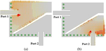
Where m = n = 1, 2,…, and εr be the relative permittivity of the substrate. The size of the EMCRs are made different to achieve distinct frequency bands. The top-side and bottom-side EMCRs are responsible for radiation at 2.6 and 4.9 GHz. These frequency bands can be designed independently by varying the dimensions of the EMCRs. The full-wave performances of the proposed antenna are depicted in Fig. 5. The antenna achieves better than −20 dB return loss and more than 34 dB port isolation. High isolation is achieved due to the weak cross-coupling path between two 50Ω orthogonal feed lines. The electric and magnetic field distributions are illustrated in Figs 6 and 7, respectively. It is seen that the maximum E-fields are observed at the outer-edge of the top side and bottom side of the EMCRs.
Simulation responses of the proposed QMSIW antenna.

Electric-field distributions. (a) At 2.6 GHz. (b) At 4.9 GHz.

Magnetic-field distributions. (a) At 2.6 GHz. (b) At 4.9 GHz.

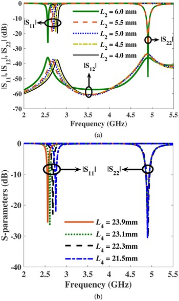
The variation of radiating bands due to the parameters L 2, L 3, and L 4 are studied. To reconstruct the radiating bands (f 1 and f 2), the parameters L 2, L 3, and L 4 can be varied individually/simultaneously as per the application requirements. Due to the variation of dimension of the parameters L 2, L 3, and L 4, the capacitive loading on the cavity is modified which results in tuning of radiating frequencies. The tuning of first radiating band is determined by varying the parameters L 2 and L 4 as shown in Fig. 8. It is observed that the first radiating band is shifted toward left when the parameters L 2 and L 4 increase without altering the second radiating band. The first radiating band can be tuned in the frequency range of 2.56–2.78 when L 2 (L 4) varied from 6.0 to 4.0 mm (23.9 to 21.5 mm). Similarly, the designing of second radiating band is realized by varying the parameter L 3 as depicted in Fig. 9. From the figure, it is seen that the second radiating band is shifted toward right when the parameter L 3 decreases without any effect on the first radiating band. The second operating band can be tuned in the frequency range of 4.87–5.13 when the parameter L 3 varied from 12.3 to 10.7 mm. Therefore, the radiating frequency bands can be designed independently/simultaneously by varying the dimensions of the EMCRs as per applications.
Tuning of first resonating frequency. (a) Due to L 2. (b) Due to L 4.

Tuning of second resonating frequency.

Based on the above studies, a simple design approach has been suggested.
(1) Select the dimension of the FMSIW cavity by following the design equations for resonant frequency (1)–(3).
(2) Produce HMSIW by symmetrical cutting of the FMSIW. This HMSIW is then cut symmetrically to form QMSIW.
(3) The resonant frequencies of the HMSIW and QMSIW are determined by using the equations (4)–(8).
(4) Insert a slot on the top surface of the QMSIW to construct two EMCRs which exhibit the self-diplexing characteristic.
(5) Select the dimension of the top EMCR responsible for first radiating band as 0.22λg × 0.29λg.
(6) Select the dimension of the top EMCR responsible for second radiating band as 0.28λg × 0.50λg.
(7) Optimize the parameters L a and L b to achieve proper impedance matching.
(8) Vary the parameters L 2, L 3, and L 4 for designing of radiating frequency bands independently.
(9) Repeat last two steps to obtain the desired antenna characteristics.
Fabrication, measurement, and comparative analysis
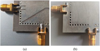
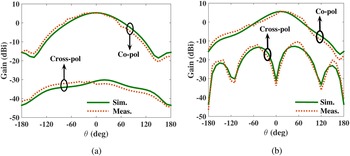
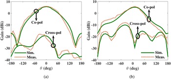
To support the theoretical analysis, the proposed antenna is fabricated and demonstrated for LTE and PSB applications. Figure 10 shows the photograph of the fabricated antenna. All the experiments are carried out by employing excitation at one port and terminating the other port by 50Ω load. The input matching and isolation are measured using Rohde and Schwarz vector network analyzer. Figure 11 depicts the performances of the full-wave simulated and measured reflection coefficients (|S 11| and |S 22|) and isolation (|S 12|). The far-field performances of the fabricated prototype in two-orthogonal planes of Φ = 0° and Φ = 90° at 2.6 and 4.9 GHz are demonstrated inside an anechoic chamber. The full-wave simulated and measured peak gains and radiation efficiency are illustrated in Figs 12 and 13, respectively. The full-wave simulated and measured radiation patterns of the fabricated antenna at 2.6 and 4.9 GHz are depicted in Figs 14 and 15, respectively. The measured and full-wave simulated performances are very consistent as expected. However, very small deviation is seen between full-wave simulated and measured performances due to fabrication tolerance and connector loss. The performances of the fabricated prototype are summarized as follows:
(1) Simulation
(a) The input return losses |S 11| and |S 22| are better −22 dB.
(b) The port isolations are 36.07 and 36.13 dB at 2.6 and 4.9 GHz, respectively.
(c) The full-wave peak gains are 5.34 and 5.56 dBi at 2.6 and 4.9 GHz, respectively.
(d) The radiation efficiencies of the proposed antenna are 89.1and 95.7% at 2.6 and 4.9 GHz, respectively.
(e) The FTBR and co-to-cross polarization level are better than 22 and 20 dB, respectively.
(2) Measurement
(a) The return losses |S 11| and |S 22| of the fabricated antenna are > −21 dB at all the radiating frequencies.
(b) The port isolations (|S 12|) of the fabricated antenna are found to be 36.69 and 35.23 dB at 2.6 and 4.9 GHz, respectively.
(c) The measured peak gains are 5.12 and 5.59 dBi at 2.6 and 4.9 GHz, respectively.
(d) The measured radiation efficiencies of the fabricated antenna are 90.2 and 95.4% at 2.6 and 4.9 GHz, respectively.
(e) The FTBR and co-to-cross polarization level are very consistent to the full-wave simulated performances.
Fabricated prototype. (a) Front view. (b) Back view.

Full-wave simulated and measured magnitude responses of the suggested SDA.

Full-wave simulated and measured gain.

Full-wave simulated and measured efficiency.

Full-wave simulated and measured radiation pattern at 2.6 GHz. (a) E-plane (ϕ = 0°). (b) H-plane (ϕ = 90°).

Full-wave simulated and measured radiation pattern at 4.9 GHz. (a) H-plane (ϕ = 0°). (b) E-plane (ϕ = 90°).

A comparative analysis is discussed on performance indicators (size, isolation, peak gain, return loss and FTBR) between the proposed antenna and previously reported works. Table 1 illustrates the performance comparison of state-of-the-art dual-frequency antennas. Compared to [Reference Zhang, Hong, Zhang and Wu8–Reference Barik, Cheng, Dash, Pradhan and Karthikeyan15], the proposed prototype is ultra-compact. The size of the manufactured antenna is 74.3% smaller than the most compact self-diplexing antenna reported in [Reference Barik, Cheng, Dash, Pradhan and Karthikeyan14]. The proposed antenna achieves highest port isolation when compared with [Reference Zhang, Hong, Zhang and Wu8–Reference Barik, Cheng, Dash, Pradhan and Karthikeyan15]. The antenna exhibits good peak gain, FTBR, and co-to-cross polarization level when compared with existing works in [Reference Zhang, Hong, Zhang and Wu8–Reference Barik, Cheng, Dash, Pradhan and Karthikeyan15]. Therefore, the proposed self-diplexing cavity-backed QMSIW slot antenna is suitable for dual-frequency compact communication systems.
Performance comparison between proposed and previously reported self-diplexing antennas

Conclusions
In this article, the design of a ultra-compact high-isolation cavity-backed self-diplexing antenna employing QMSIW for LTE and PSB applications is presented. The proposed antenna is configured by utilizing a QMSIW, one slot, and two 50Ω feed lines. A slot is placed on the top side of the QMSIW to produce two EMCRs for radiating at 2.6 and 4.9 GHz. These frequency bands can be designed individually by varying the dimensions of the eighth-mode resonators. For validation, the suggested antenna is fabricated and demonstrated. The size of the fabricated prototype is ultra-compact due to the utilization of QMSIW cavity. The port isolation is better than 35 dB at all the radiating bands. The fabricated prototype exhibits good peak gain, FTBR, and co-to-cross polarization levels along with efficiency >85% at all the frequency bands.
Acknowledgment
The authors extend their appreciation to the Deanship of Scientific Research at Jouf University for funding this work through research grant No (DSR-2021-02-0212).
 Ayman A. Althuwayb received the B.Sc. degree (Hons.) in electrical engineering (electronics and communications) from Jouf University, Saudi Arabia, in 2011, the M.Sc. degree in electrical engineering from California State University, Fullerton, CA, USA, in 2015, and the Ph.D. degree in electrical engineering from Southern Methodist University, Dallas, TX, USA, in 2018. He is currently an Assistant Professor with the Department of Electrical Engineering at Jouf University, Kingdom of Saudi Arabia. His current research interests include antenna design and propagation, microwaves and millimeter-waves, wireless power transfer, ultrawideband and multiband antennas, filters, and others.